
Chapter 7. LCD displays
- Communicating with the common Hitachi HD44780 parallel LCD
- Building a serial LCD weather station
- Displaying text and images on the KS0108 graphic LCD
By now you’ve begun to master the art of interacting with your Arduino in both the analog and digital domains. You’ve made LEDs blink, you’ve transformed piezos into pentatonic musical keyboards, and in chapter 6 you graduated from interfacing with everyday components such as potentiometers to working with ultrasonic and infrared distance sensors.
Aside from blinking your first LEDs in chapter 1, most of your interaction with the Arduino thus far has been concerned with obtaining real-world input and output from your Arduino. Most of the work you do with the Arduino will be concerned with doing exactly that. But you’ll also encounter scenarios where your project will need to receive information back from the Arduino, so in this chapter we’ll revisit the realm of visual feedback by exploring various liquid crystal displays, more commonly called LCDs.
LCDs are embeddable screens found in all sorts of consumer electronics. There are many different types of LCDs, however, so in section 7.1 you’ll learn about the common LCDs you’ll use in your future Arduino endeavors.
7.1. Introduction to LCDs
Liquid crystal displays (LCDs) have become ubiquitous: from the moment you wake up to the moment you go to bed, your day is guided by many interactions with LCD screens.
You wake up in the morning and, upon seeing the LCD on your alarm clock, you realize you’re running an hour late. You use the LCD on your mp3 player to navigate to the song you absolutely must listen to next. You look at the number on your phone’s LCD and decide to answer or ignore the call. And before bed, you look at the alarm clock again to make sure it’s set for tomorrow.
Viewing LCD displays is one of the primary ways we experience electronic data, and in this chapter we’ll look at the common types of LCDs you can add to your future Arduino projects.
The first two types of LCD displays are parallel and serial LCDs, and they’re normally character displays. Character displays are ideal for displaying some sort of text to the user, and even small shapes or icons (usually 5 x 7 pixels). The other type of LCD we’ll cover in this chapter is basic graphic LCDs, which as you may have guessed are great for drawing graphics and images.
But before we explore character displays, let’s take a look at String variables, which are how we deal with text in Arduino.
7.1.1. String variables: String type vs. char type
Pairing an Arduino with an LCD is a great way to display text feedback and add menu-browsing capabilities to your project. So how exactly does one send text to an LCD?
In the Arduino and other computer programming languages, text is thought of as a sequence of characters. For example, if you were to put together the four characters T, e, x, t, you would make the word Text. In this way, all text is represented in code as an array of characters.
There are two main ways to create your text in code (or, more generally, to create any sequence of characters). One way is to use the String data type, and the other is to use a null-terminated array of type char. If that makes complete sense to you, great! If not, don’t worry; it’s much simpler than it sounds. Let’s take a look and see what the fuss is all about.
As previously mentioned, all text in your code will actually be an array of characters. For more control, a container class called the String class was created, which enables you to manipulate this array of characters in many complex ways. You can compare two Strings against each other to see if they’re the same, search a String of text for a substring, and append characters to the end of a String or even concatenate multiple Strings. Table 7.1 provides an overview of the various functions that can be performed on a String variable. As you can see, the String class is extremely powerful and can be useful for preparing text on your character display.
Table 7.1. The functions of the Arduino String class
|
Function |
Description |
|---|---|
| charAt() | Accesses a particular character of a String |
| compareTo(String two) | Tests if two Strings are equal, or if one comes before or after the other |
| concat(String two) | Combines two Strings into one new String |
| endsWith(String two) | Tests whether a String ends with the chars of another |
| equals(String two) | Performs case-sensitive comparison of two Strings’ equality |
| equalsIgnoreCase(String two) | Performs non-case-sensitive comparison of two Strings’ equality |
| getBytes(char [ ], int length) | Copies a String’s characters to the supplied buffer |
| indexOf(val) indexOf(val, int index) |
Locates a character or String within another String, starting from the front (val can be a char or String) |
| lastIndexOf(val) lastIndexOf(val, int index) |
Locates a character of String within another String, starting from the end (val can be a char or String) |
| length() | Returns the length of the String in characters |
| replace(String one, String two) | Replaces all instances of a character or substring with another |
| setCharAt(int index, char c) | Sets or changes a particular character of a String |
| startsWith(String s) | Returns a Boolean (true/false) indicating whether a String starts with the characters of another String |
| substring(int start) substring(int start, int end) |
Returns a substring of a String |
| toCharArray(char [ ], int length) | Copies a String’s characters to the supplied array |
| toLowerCase() | Returns a copy of the original String with all characters lowercase |
| toUpperCase() | Returns a copy of the original String with all characters uppercase |
| Trim() | Returns a copy of the original String with all whitespace before and after the String removed |
Declaring a String is easy. Here are a couple of examples:
String s = "Arduino in Action Rocks!";
String s = String(13);
Both of these lines will create a String called s, the first from a constant string of characters, and the second from an integer number (defaults to base 10).
The String functions outlined in table 7.1 provide many utilities. For example, to combine these two lines,
String first = "Hello";
String second = " World";
into a new String third, simply call this function:
String third = first.concat(second);
String third would now be “Hello World”. But as is often the case, this added functionality of the String class comes at the price of memory, and because memory can be precious on the Arduino, you may want to bypass the String type and use the more lightweight array of type char directly.
Note
You may have noticed that up until now we’ve been referring to Strings with a capital S; for char strings, we’ll use a lowercase s.
There are many ways to represent a string as a char array, as you can see in table 7.2. Character strings normally end with a null character (ASCII code 0), which ensures that Arduino functions such as Serial.print() know exactly where the end of the string is. This is why the arrays two[5] and three[5] in table 7.2 are five characters long, even though text is technically only four characters long; the Arduino compiler automatically inserts the extra null character at the end. One last important reminder: constant strings are always declared inside double-quotes, whereas single chars are declared in single-quotes. See table 7.2 for examples.
Table 7.2. Possible char type string array initializations
|
Declaration |
Description |
|---|---|
| char one[10]; | Declares a non-initialized char array |
| char two[5] = { 't', 'e', 'x', 't' }; | Declares an array with an extra char so the compiler can automatically add the null char |
| char three[5] = { 't', 'e', 'x', 't', '�' }; | Same as the previous example with the null char added explicitly |
| char four[ ] = "text"; | Compiler automatically sizes to the string constant plus the null character |
| char five[5] = "text"; | Initializes to explicit size and string constant |
| char six[10] = "text"; | Initializes the array with extra space for a larger string |
At this point, we’ve hopefully demystified the differences between the String type and the array of char type strings that you’ll encounter when working with the Arduino and LCDs. Next we’ll look at wiring up your first LCD, so without further ado, please welcome the Hitachi HD44780.
7.2. Parallel character LCDs: the Hitachi HD44780
The Hitachi HD44780 is one of the most common LCD controller chips designed for embedded systems and microcontrollers. The chip supports many shapes and sizes of displays, and in this example, we’ll use one to drive a 16 x 2 LCD (2 rows, 16 characters long).
The pervasiveness of the Hitachi HD44780 controller (and other similar LCD chips) is great news for you, because they can usually be purchased cheaply or salvaged from your old machines. Some are even pretty fancy, offering single and multicolor (RGB) backlighting.
Backlit LCDs have lights (LEDs) embedded in the screen, which can be turned on to make the screen glow. This isn’t only great for low-lit situations, but also for visual feedback. For example, an LCD such as the Hitachi HD44780 that has an RGB backlight can light the screen with different colors, reporting the status of your Arduino. You might turn the screen red to let the user know something is wrong, or green to signal that things are OK.
7.2.1. 4-bit or 8-bit?
Hitachi HD44780-based LCDs come in many different configurations, but there are two ways in which you can interface with the Hitachi HD44780 LCD: 4-bit and 8-bit. The main tradeoff between the 4-bit and 8-bit configurations is the number of pins needed on the Arduino versus speed of execution.
Because it’s a parallel LCD, the simplest means of communication would be to send the full byte (8-bits) of data all at once (in a 1-byte message). To do this would require at least 10 I/O pins on the Arduino. In contrast, the 4-bit mode requires just 6 I/O pins and splits the byte into two 4-bit nibbles. This saves pins but takes a little more time (two messages versus one message). The 4-bit mode is still “parallel” in the sense that you receive 4 bits at a time, but it’s split into two messages that are sent one after another.
7.2.2. Library and functions
Luckily for us, working with LCDs based on the Hitachi HD44780 chipset (or other similar chipsets) is a breeze. As was mentioned in chapter 4, one of the standard libraries preinstalled in the Arduino IDE is the LiquidCrystal LCD library. It’s compatible with both 4-bit and 8-bit configurations and provides you with many useful functions for controlling your LCD.
Table 7.3 details the functions available in the LiquidCrystal library.
Table 7.3. The functions available in the LiquidCrystal LCD library
|
Description |
|
|---|---|
| begin(int column, int row) | Sets the dimensions of the screen |
| clear() | Resets and clears everything on the display |
| home() | Sets the cursor to the upper left of the LCD |
| setCursor(int column, int row) | Sets the cursor to the position passed in |
| write(byte value) | Writes a character to the current cursor position |
| print(data) | Prints text to the string; can be a char, byte, int, long, or string/String |
| cursor() | Displays an underscore at the current position |
| noCursor() | Hides the cursor character |
| blink() | Blinks the cursor character |
| noBlink() | Disables the cursor character from blinking |
| display() | Turns the display on and restores text if turned off by noDisplay() |
| noDisplay() | Turns off the display, saving current text |
| scrollDisplayLeft() | Scrolls text one space to the left |
| scrollDisplayRight() | Scrolls text one space to the right |
| autoscroll() | Automatically scrolls text, pushing previous character one position to the left or right |
| noAutoscroll() | Disables autoscrolling |
| leftToRight() | Sets the direction of text being displayed |
| rightToLeft() | Sets the direction of text being displayed |
| createChar(int num, byte[] charData) | Defines a custom 5 x 8 character |
7.2.3. Circuit diagram
Now that we have a good understanding of how the Hitachi HD44780 communicates on both the hardware and software level, we’re ready to start connecting everything. For this, you’re going to need the following components:
- An Arduino (such as Arduino Uno or Mega).
- A Hitachi HD44780-based LCD screen.
- A 10k ohm potentiometer or trimpot (R1).
- A resistor. (R2. This is only needed if your LCD has a backlight, and the value of the resistor will depend on the backlight of your LCD; see additional notes that follow.)
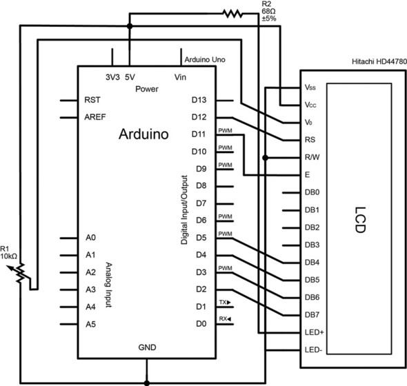
Figure 7.1 shows the connections required to hook up your LCD to your Arduino.
Figure 7.1. The connections between a Hitachi HD44780-based LCD display and the Arduino
Note
In figure 7.1, the backlight LED+ (if present) is connected to 5V on the Arduino via a 68-ohm current-limiting resistor. This value may differ and should be calculated based on the specification of your screen backlight. There are many tutorials and online calculators to help you determine the optimal value for your screen; a good place to start is the “LED Current Limiting Resistors” tutorial on the SparkFun Electronics site: http://www.sparkfun.com/tutorials/219.
7.2.4. Connecting everything up in 4-bit mode
To save your precious I/O pins for other sensors and devices, you can connect everything in 4-bit mode. The LiquidCrystal library automatically takes care of the logic required to communicate in 4-bit mode, so there’s no difference in terms of coding. Your completed wiring will look similar to figure 7.2.
Figure 7.2. Power and contrast wiring for the Hitachi HD44780 parallel LCD

If possible, the first thing you should do is look up the data sheet for your particular LCD. This is useful for identifying the pin layout of your LCD if the layout isn’t already silk-screened onto the LCD circuit board itself. If there isn’t a printed label on your board, or a sticker with the model number, and you purchased the LCD from an online hobby store, check the retailer’s website because they often provide links to the data sheets. If you salvaged your LCD from an old printer or other machine, and you can’t find any information about the pin layout, be careful. Most 16-pin Hitachi 77480-compatible LCDs will follow a similar pin layout, but incorrectly wiring up the LCD can damage both the LCD and your Arduino.
As per the circuit diagram in figure 7.1, first connect the Vss pin to GND. The next pin, Vcc, supplies power to the LCD and should be connected to +5V on the Arduino (or 3.3V depending on your LCD). Next, you’ll want to connect the V0 pin on the LCD to the wiper (middle leg) of a 10k linear potentiometer. Connect the left leg to +5V and the right to GND. This is used to set the contrast of your LCD, and you may prefer to use a trimpot if the contrast is something you want to set and forget.
Note
Ground and power rails have been created using the vertical columns labeled “+” and “-”.
Now that power and contrast are all set, you can move on to your communication lines. Connect the Register Select (RS) pin on the LCD to Arduino digital pin 12. This RS pin is used to control where in the LCD’s internal memory the Arduino will write the current character. Next, wire the Enable (E) pin to Arduino digital pin 11. Enable is what actually allows writing to those registers. Read/Write (RW) can be connected directly to GND or to Arduino digital pin 10 (optional). Tying RW to digital pin 10 instead of ground gives you the added functionality of being able to send information back from the LCD if you so choose. If you don’t wish to read from the LCD (which you won’t in most cases), save yourself the digital pin and connect RW directly to ground.
Since you’re running in 4-bit mode, the next four pins on the LCD (DB0–DB3) don’t need to be connected. That brings you to LCD bits DB4–DB7: DB4 should be connected to Arduino digital pin 5, DB5 to digital pin 4, DB6 to digital pin 3, and DB7 to digital pin 2. If your LCD has a backlight, now would be the time to connect the backlight LED+ to +5V on the Arduino through a series resistor (see the earlier note in section 7.2.3), and the LED- to GND on your Arduino.
Voilà! You’re now ready to test your first sketch and communicate with your LCD. If you want to triple-check your connections, please refer to table 7.4.
Table 7.4. The required circuit connections between the Hitachi HD44780 LCD and the Arduino
|
Arduino pin |
LCD pin |
|---|---|
| GND | Vss |
| +5V | Vcc |
| Pin 2 (wiper) of 10k linear potentiometer | V0 |
| D12 | Register Select (RS) |
| D11 | Enable (E) |
| GND or D10 (optional) | Read/Write (RW) |
| D5 | DB4 (bit 4) |
| D4 | DB5 (bit 5) |
| D3 | DB6 (bit 6) |
| D2 | DB6 (bit 7) |
| +5V through a series resistor (for example, 68 ohm) | LED+ |
| GND | LED- |
7.2.5. Sketch for writing to the Hitachi HD44780
Now that everything is wired up, let’s print something to the screen. Open up the Arduino IDE and carefully copy the code from the following listing into your empty sketch (or simply run the provided sketch).
Listing 7.1. Writing text onto your LCD

First, you must include the LiquidCrystal library header file to tell Arduino that you wish to use the LiquidCrystal library.
Next, you create an instance of the Liquid-Crystal class, lcd, and pass in the Arduino pins to which your LCD is connected ![]() . The number of arguments you pass in to the constructor automatically configures the lcd object to run in 4-bit or 8-bit mode.
. The number of arguments you pass in to the constructor automatically configures the lcd object to run in 4-bit or 8-bit mode.
In your setup routine, configure the size of your screen ![]() , and then print some text to the LCD
, and then print some text to the LCD ![]() . Because the text you want to print is longer than one row, you print the first half, then go to the second line using the
setCursor
. Because the text you want to print is longer than one row, you print the first half, then go to the second line using the
setCursor ![]() method and then print the second half of the text
method and then print the second half of the text ![]() .
.
7.2.6. Upload and test
Connect the USB cable to your Arduino and verify that the sketch compiles. Make sure your board and serial port are selected in the Tools menu, and click the Upload icon. Shortly after the sketch completes, your LCD should display the words “Arduino in Action Rocks!” (It should look similar to the image in figure 7.3.) Exciting! If you don’t see anything displayed on the screen, or if the text is too dim, turn the potentiometer wired to V0 to adjust the contrast of the screen.
Figure 7.3. Completing the wiring for the Hitachi HD44780 parallel LCD

Seeing text on your LCD for the first time is always very exciting, especially when the display is giving you useful information. Now that you’ve tackled displaying static text in your first LCD project, let’s build a weather station to monitor temperature in real time. And while we’re at it, let’s also learn about another type of character display, the serial LCD.
7.3. Serial LCD weather station
Want to save even more pins on your Arduino, or perhaps you’d just prefer fewer dangling wires? Serial LCDs are another affordable option, and they require only three pins to operate. They work a little differently than parallel LCDs, interpreting serial commands (TTL or transistor-transistor logic, to be exact) over your Arduino’s TX pin into special commands or output to the LCD (more on this later). The catch is that they’re a little more expensive than their parallel brethren, although prices have come down significantly in recent years. Additionally, you can purchase a serial LCD backpack, turning your Hitachi HD44780 parallel LCD into a serial LCD.
In this section, we’re going to look at connecting and communicating with a serial LCD and build a real-time weather station to monitor the temperature of your home.
7.3.1. Serial vs. parallel LCDs
The way in which serial LCDs communicate with the Arduino is fundamentally different than the parallel LCDs we saw in section 7.2, although operationally they’re very similar.
If you remember our study of parallel LCDs, we sent either 4- or 8-bit messages from the Arduino to the LCD, instructing it to move the cursor or print a character to the screen. The main difference is that serial LCDs send messages one bit at a time (serially), requiring only one communication line. Once wired up, communicating with the serial LCD is as easy as sending the appropriate single-byte command flag using Serial.print(command) to perform various tasks (move the cursor, turn the display off, and so on) or you can send plain old characters to print text to the screen: Serial.print("text").
There are a number of commands you can send to the screen, so it would be helpful to create helper functions that automatically set the appropriate command before passing the message you want. Luckily, the Arduino community has already done this for various serial LCD models, and it has created Serial LCD libraries based on the official LiquidCrystal library, but with a few added features.
7.3.2. SerLCD library and functions
The library you’ll be using to communicate with your serial LCD in this section is called SerLCD. The library is written to be used with the 16 x 2 SparkFun (or compatible) serial LCDs and backpacks, but with a simple modification the library can be used with most serial LCDs on the market.
Unlike the LiquidCrystal library that comes installed within the Arduino IDE, SerLCD is a contributed library, which means it has been written by a member of the Arduino community and isn’t currently rolled into the official release. There are a few things you need to do in order to get SerLCD up and running, so please read the following instructions carefully.
First, you’ll need to download the SerLCD library source from http://arduino.cc/playground/Code/SerLCD. Download and extract the folder called serLCD and put that folder in your sketchbook/libraries folder, as described in chapter 4 (section 4.4 on contributed libraries).
The SerLCD library uses the built-in SoftwareSerial library (discussed in section 4.3.11), allowing the LCD to work over the serial communication lines while leaving the hardware serial port open on the Arduino. This is great news, because it will allow the simultaneous use of multiple serial peripherals alongside the LCD, albeit with a few important considerations. Please refer back to section 4.3.11 for more information on using multiple serial devices simultaneously with the SoftwareSerial library.
The SerLCD library has implemented most of the functions available in the LiquidCrystal library (table 7.3), so sharing your code between the parallel and serial LCDs will only require a few minor changes. Table 7.5 details the functions available in the SerLCD library, which even include the ability to adjust the contrast of the screen using pulse-width modulation (on SparkFun SerLCD and compatible displays).
Table 7.5. The functions available in the SerLCD library
|
Function |
Description |
|---|---|
| serLCD(int pin) | Constructor that specifies the TX pin to the LCD |
| clear() | Resets and clears everything on the display |
| clearLine(int num) | Resets and clears a specific line |
| selectLine(int num) | Moves the cursor to the beginning of a specific line |
| setBrightness(int num) | Sets the contrast of the LCD (only on some LCDs) |
| home() | Sets the cursor to the upper left of the LCD |
| print(data) | Prints text to the LCD |
| setSplash() | Saves the first two lines displayed as the startup “splash” screen |
| toggleSplash() | Enables or disables a startup “splash” screen |
| leftToRight() | Sets the direction of text being displayed |
| rightToLeft() | Sets the direction of text being displayed |
| blink() | Blinks the cursor character |
| noBlink() | Disables the cursor character from blinking |
| cursor() | Displays an underscore character at the current position |
| noCursor() | Hides the cursor character |
| display() | Turns the display on and restores text if turned off by noDisplay() |
| noDisplay() | Turns off the display, saving current text |
| setCursor(int row, int column) | Sets the cursor to the position passed in |
| createChar(int num, byte[] charData) | Defines a custom 5 x 8 character |
| printCustomChar(int num) | Prints a custom character |
Note
If you’re using a serial LCD that isn’t compatible with the SparkFun serial LCD, there are a few changes you must make to the SerLCD library. If you open up SerLCD.h, you’ll find a list of commands and flags set in hexadecimal notation. Refer to your LCD’s datasheet and update these accordingly, and you should be all set.
With the SerLCD library installed, you’re ready to start wiring up your LCD, but first let’s take a look at the temperature sensor that you’ll be using.
7.3.3. The Maxim IC DS18B20 temperature sensor
The DS18B20 temperature sensor by Maxim uses the Maxim one-wire protocol and is becoming one of the most popular temperature sensors on the market. The one-wire protocol allows one or more one-wire slave devices to communicate with a master device over a single data line, which means that you can easily connect many of these sensors to your Arduino without taking up many inputs on the Arduino. They’re inexpensive, reliable, calibrated, and robust enough to communicate over long wires for remote applications.
Easy to wire up, the contributed OneWire and DallasTemperature libraries also make communicating with the sensor simple.
7.3.4. OneWire and DallasTemperature libraries
In order to communicate with your DS18B20 temperature sensor, you need the OneWire Arduino library; using the DallasTemperature library is optional. The OneWire library will allow you to begin communicating with your temperature sensor; the Dallas-Temperature library has some useful features such as Celsius to Fahrenheit conversion, and the ability to easily code and read more than one temperature sensor on the same bus. As such, we’re going to be using the DallasTemperature library in this example, and recommend you do too.
Note
If you don’t use the DallasTemperature library, you’ll need to execute the less readable OneWire library commands, which can be referenced online at http://www.pjrc.com/teensy/td_libs_OneWire.html.
Download the latest version of the OneWire library from www.arduino.cc/playground/Learning/OneWire and the DallasTemperature library from http://milesburton.com/Dallas_Temperature_Control_Library (you’ll want version 3.7.2 or greater). Place the two library folders into your Arduino sketchbook libraries directory.
You’re now ready to wire everything up and upload the code.
7.3.5. Circuit diagram
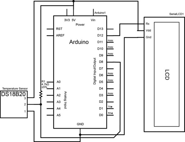
Figure 7.4 is an overview of the circuit you’ll wire up for the serial LCD–powered weather station.
Figure 7.4. Circuit diagram for a weather station using the SparkFun (or compatible) serial LCD, and the DS18B20 one-wire digital temperature sensor
7.3.6. Connecting everything up
Before connecting everything up, you should prepare all the parts needed for the project:
- An Arduino
- A serial LCD (SparkFun-compatible 16 x 2 serial LCD or backup recommended)
- A DS18B20 temperature sensor
- A 4.7k ohm resistor (R1)
Once you have the required parts, making your weather station couldn’t be any simpler. As described in table 7.6, simply connect the Vdd pin on the LCD to 5V on your Arduino to get power going to the LCD. Next, wire the GND pin on the LCD to your Arduino’s GND pin. Finally, the RX (receive) pin on your LCD should connect to any of the digital pins on your Arduino—table 7.6 and the schematic in figure 7.4 show it connected to pin 12.
Table 7.6. Required circuit connections between the serial LCD and the Arduino
|
Arduino pin |
LCD pin |
|---|---|
| GND | GND |
| 5V | Vdd |
| D12 (or any digital pin) | RX |
If you aren’t using the serLCD library (which uses the SoftwareSerial library for communication), you can also directly connect the LCD’s RX pin to the TX (D1) pin on the Arduino, although you’ll lose the benefits of using a software serial port, as discussed earlier.
Wiring up the DS18B20 one-wire temperature sensor is also a breeze. As described in table 7.7, connect pin 1 on the sensor to GND, connect pin 2 to a digital input (such as digital pin D8 on the Arduino), and pin 3 on the sensor to 5V on the Arduino. Lastly, you need to wire a 4.7k ohm pull-up resistor between pin 2 on the DS18B20 and 5V—one simple way is to put the resistor directly between pins 2 and 3 on the sensor itself. For the DS18B20’s pin layout, see figure 7.5. Your completed wiring should look similar to that in figure 7.6.
Figure 7.5. Pin layout for the DS18B20 temperature sensor

Figure 7.6. Completed wiring for a DS18B20-based LCD weather station

Table 7.7. Required circuit connections between the DS18B20 one-wire temperature sensor and the Arduino
|
Arduino pin |
DS18B20 one-wire temperature sensor |
|---|---|
| GND | Pin 1 |
| 5V | Pin 3 and pin 2 through a 4.7k ohm resistor |
| Pin 8 (or any digital pin) | Pin 2 |
7.3.7. Sketch for an LCD weather station
Now that everything is wired up, you can get information from the temperature sensor and display it on the screen. Open up the Arduino IDE and carefully copy the following code into your empty sketch (or simply run the provided sketch).
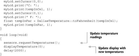
Listing 7.2. Weather station

First you must import the three libraries we want to use ![]() . Next, set up the temperature sensors by defining the port the temperature sensor is connected to
. Next, set up the temperature sensors by defining the port the temperature sensor is connected to ![]() .
.
You can then create a new OneWire object and DallasTemperature object ![]() . You configure the LCD by creating a new serLCD object with the SoftwareSerial port number (digital pin) the LCD is using
. You configure the LCD by creating a new serLCD object with the SoftwareSerial port number (digital pin) the LCD is using ![]() .
.
Note
When printing the temperature value, you can change the decimal precision (how many decimal places are printed) by modifying the print function arguments. For example, myLcd.print(tempInCel, 4); prints temperatures with four decimal places.
Once you’ve copied the code into the Arduino IDE, you’re ready to see the code in action.
7.3.8. Upload and test
If you haven’t done so already, make sure you’ve properly installed the three required libraries (SerLCD, OneWire, and DallasTemperature). You’re now ready to connect the USB cable to your Arduino and verify that the sketch compiles. Make sure your board and serial port are selected in the Tools menu, and click the Upload icon. Shortly after the sketch completes uploading, your LCD should display the temperature in both Celsius and Fahrenheit, updating its reading every two seconds.
Congratulations! Your Arduino will now monitor the temperature of your room. Want to take this one step further? You can purchase a tri-color (RGB) backlight parallel display and use the color of the screen to indicate from a distance whether you should turn on the heat or air conditioning. Perhaps when the temperature crosses a certain threshold, the screen turns red, letting you know you should cool the place off, or vice versa.
This leads us to a good question: how can LCDs be used to display things other than text? Well, pairing an LCD with LEDs is one way, but for many more possibilities, you can turn to graphic LCDs.
7.4. Graphic LCDs: the Samsung KS0108 GLCD
If you need feedback other than text displayed on a screen, look no further. Graphic LCDs (GLCDs) are one of the most common peripherals you’ll come into contact with on a daily basis, from the cellphone in your pocket to the laptop on your desk.
Whereas parallel and serial character displays allocate a very small number of pixels for each character (typically 5 x 8 pixels), graphic LCDs use the entire screen as your canvas. That means you have complete control to draw whatever you like, pixel by pixel. Imagine the possibilities: you could use a graphic LCD to build a fully functional Arduino-powered video game, or perhaps to draw custom knobs and sliders to visualize your sensors’ data stream. Graphic LCDs are extremely useful displays, unleashing the power of the pixel to create anything from homemade calculators to audio-responsive level meters.
So how many pixels do you get? Graphic displays come in many different sizes, but we’re going to use the common KS0108-based GLCD, which typically comes in a monochrome 128 x 64 pixel configuration. Like the character displays discussed earlier in this chapter, the KS0108 GLCD has an extensive library that allows you to easily draw to your screen.
7.4.1. Library and functions
To communicate with the KS0108 GLCD, you’ll be using the KS0108 Graphics LCD Library available at www.arduino.cc/playground/Code/GLCDks0108. Download the official release, or for the latest optimizations, download the bleeding-edge release candidate hosted at http://code.google.com/p/glcd-arduino/downloads/list.
Table 7.8 lists the various functions in the library that you’ll use to move around on and draw to your display.
Table 7.8. The functions available in the GLCDks0108 library
|
Function |
Description |
|---|---|
| Init(bool inverted) | Initializes the library |
| ClearScreen() | Resets and clears everything on the display |
| DrawBitmap(bitmap, int x, int y, color) | Draws the provided bitmap image at the x,y location |
| SelectFont(font) | Switches to the fixed-width font provided |
| PutChar(char c) | Prints a char at the current position |
| GotoXY(int x, int y) | Moves position to x,y (top left is 0,0) |
| CursorTo(int x, int y) | Locates cursor for printing text |
| PrintNumber(long n) | Prints a number to the screen at the current position |
| Puts(string t) | Prints a text string at the current cursor position |
| DrawLine(int x1, int y1, int x2, int y2, color) | Draws a line |
| DrawVertLine(int x, int y, int length, color) | Draws a vertical line |
| DrawHoriLine(int x, int y, int length, color) | Draws a horizontal line |
| DrawRect(int x, int y, int width, int height) | Draws a rectangle |
| InvertRect(int x, int y, int width, int height) | Inverts pixels within given rectangle |
| DrawRoundedRect(int x, int y, int width, int height, int radius, int color) | Draws a rectangle with rounded corners |
| FillRect(int x, int y, int width, int height, int color) | Draws a filled rectangle |
| DrawCircle(int x, int y, int radius, color) | Draws a circle with the center at x,y |
| SetDot(int x, int y, color) | Fills a pixel at the specified location |
Note
For the functions in table 7.8 with a color parameter, WHITE clears a pixel and BLACK fills a pixel.
While communicating with the KS0108 GLCD is intuitive using the GLCDks0108 library, wiring up the GLCD is a little more involved than the character displays we discussed earlier. Let’s take a look at how exactly you can wire up your screen and what you should watch out for.
7.4.2. Circuit diagram
To connect up your KS0108 graphic LCD, you’ll need the following:
- An Arduino Mega
- A KS0108 GLCD
- A 10k ohm potentiometer (R1)
- A 220 ohm resistor (R2)
Figure 7.7 is a circuit diagram showing how to wire a KS0108 (model with pinout A) to the Arduino Mega. There are four common versions of the KS0108 display, and the circuit diagram in this section only applies to the common LCD pinout A when connected to the Mega. If you’re using a KS0108 with any of the other pinouts or Arduino models, please skip this diagram and go straight to section 7.4.3. There you’ll find a table with all the appropriate connections you need to make. More information on determining which pinout your LCD has can also be found in section 7.4.3.
Figure 7.7. Circuit diagram for the KS0108 GLCD with pinout A connected to the Arduino Mega

7.4.3. Connecting everything up
Wiring up the KS0108 isn’t particularly difficult, although there are a lot of connections to make—20 to be exact.
The first thing you’ll need to figure out is the pinout of the KS0108 version you have. Verify the labeling on your KS0108 screen (if labeled) or refer to the screen’s data sheet. Additionally, a list of models and their pinout versions has been compiled for most of the common screens you’ll come across at www.arduino.cc/playground/Code/GLCDks0108. In this example, we used the standard SparkFun GLCD 128 x 64, which uses pinout A.
Table 7.9 provides an extensive overview of the pin assignments for each type of KS0108. Additionally, you’ll notice in table 7.9 that depending on the Arduino you’re using, the pin assignments between the GLCD and the Arduino change. This is very important and must be correct in order for the library to properly communicate with the screen.
Table 7.9. KS0108 GLCD pinouts and connections to the Arduino
|
Uno/168/328 |
Mega |
Function |
Pinout A |
Pinout B |
Pinout C |
Pinout D |
Description |
|---|---|---|---|---|---|---|---|
| 5V | 5V | 5V | 1 | 2 | 2 | 4 | |
| Gnd | Gnd | Gnd | 2 | 1 | 1 | 3 | |
| n/a | n/a | V0 | 3 | 3 | 3 | 5 | Wiper of 10k contrast pot |
| 8 | 22 | D0 | 4 | 7 | 7 | 9 | |
| 9 | 23 | D1 | 5 | 8 | 8 | 10 | |
| 10 | 24 | D2 | 6 | 9 | 9 | 11 | |
| 11 | 25 | D3 | 7 | 10 | 10 | 12 | |
| 4 | 26 | D4 | 8 | 11 | 11 | 13 | |
| 5 | 27 | D5 | 9 | 12 | 12 | 14 | |
| 6 | 28 | D6 | 10 | 13 | 13 | 15 | |
| 7 | 29 | D7 | 11 | 14 | 14 | 16 | |
| 14 (analog 0) | 33 | CSEL1 | 12 | 15 | 16 | 1 | Chip 1 select |
| 15 (analog 1) | 34 | CSEL2 | 13 | 16 | 15 | 2 | Chip 2 select |
| Reset | Rest | Reset | 14 | 17 | 17 | Connect to reset pin | |
| 16 (analog 2) | 35 | R_W | 15 | 5 | 5 | 7 | R/W |
| 17 (analog 3) | 36 | D_I | 16 | 4 | 4 | 6 | RS |
| 18 (analog 4) | 37 | EN | 17 | 6 | 6 | 6 | Enable |
| External | External | Vee (Contrast out) | 18 | 18 | 18 | Connect to one leg of 10k pot | |
| External | External | Backlight +5V | 19 | 19 | 119 | 100–330 ohm resistor to +5V | |
| Gnd | Gnd | Backlight Gnd | 20 | 20 | 20 | Connect to other leg of 10k pot |
7.4.4. Sketch for drawing to a GLCD
Now that it’s wired up, let’s get some graphics drawing. Carefully copy the following code into the Arduino IDE (or run the provided sketch), and you should be able to upload and see your screen animated.
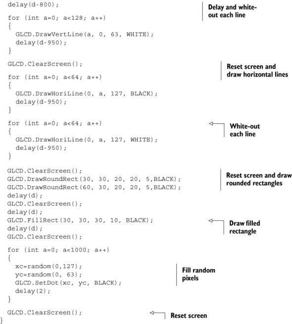
Listing 7.3. Drawing to the KS0108 GLCD

7.4.5. Upload and test
If you haven’t already installed the GLCDks0108 library, please follow the instructions to do so in section 7.4.1. Once the library has been installed, you’re ready to connect the USB cable to your Arduino and verify that the sketch compiles. Make sure your board and serial port are selected in the Tools menu and click the Upload icon.
Immediately after the sketch has been uploaded, you’ll begin to see your LCD come to life! You now have all the tools necessary to draw complex images and text to your KS0108 GLCD. You can create rich visual feedback in future applications.
7.5. Summary
In this chapter you learned how to connect three different kinds of LCD screens to your Arduino. These included parallel and serial LCDs—embeddable character displays that prove themselves useful time and time again when it’s important to provide feedback about the state of your Arduino, data from sensors, or other information. You also learned about the nifty one-wire protocol while making a homebrewed LCD-powered weather station to monitor the temperature of your home. Lastly, you learned about GLCDs—powerful displays that give you the freedom to draw and visualize images and text on screen with great precision and control.
By themselves, LCDs don’t do very much, but as you can imagine, the way you code your LCD to interact with your Arduino can enable many possibilities. Whether they’re visualizing the state of your sensors, enabling you to change and interact with different modes on your Arduino-powered project, creating the world of your video game, or displaying information from the internet (discussed further in chapter 8), LCDs will afford you great control and provide feedback in many of your projects. In a general sense, LCDs can be thought of as one of the great communicators between you and your Arduino.
But LCDs aren’t the only way for your Arduino to communicate to the outside world. It’s now time to turn to chapter 8, on communications.