
Chapter 11. Making wearables
- Creating wearable projects with the LilyPad Arduino
- Working with conductive thread
- Creating a turn-signal jacket
- Creating a wearable piano
- Making a wearable compass
The term “wearable” generally refers to clothing and accessories that incorporate computer and advanced-electronic technologies. The designs often incorporate practical functions and features as well as make a statement or establish a technological look.
Another way of imagining a wearable is that it’s a dynamic surface around your body that is capable of connecting you to devices around you, people, and places. These days most people carry a mobile phone, always on them and always on, but it’s not hard to imagine a near future in which most of our communication tools will be even smaller, perhaps even integrated into clothing or accessories that we carry with us. Wearables can be clothing like jackets or sweaters, accessories like hats or scarves, or objects that are worn or carried like necklaces or headphones.
All of these are rich areas to explore. Another mode of wearable computing that you may consider is wearable technology that can be integrated with a mobile phone or laptop using radio frequencies or Bluetooth.
In this chapter we’ll examine two platforms for creating wearable applications: the LilyPad and the Arduino Pro Mini. Each has different strengths and weaknesses, and each requires a slightly different development mentality.
The Arduino Pro Mini is a very stripped-down and simple board for more advanced Arduino users. It comes in two different versions: a lower-power version that runs at 8 MHz and a higher-power version that runs at 16 MHz. It draws slightly less current than the LilyPad and is cheaper, but it’s a little trickier when you’re just getting started.
The LilyPad is more oriented toward the development of wearables. Its connections are slightly unorthodox loops drilled into the board that are perfect for holding a thread, particularly conductive thread. It also has a large community that provides a lot of ideas and help.
We’ll start with the LilyPad.
11.1. Introducing the LilyPad
The LilyPad Arduino was designed and developed by Leah Buechley in tandem with SparkFun Electronics. The LilyPad Arduino is a microcontroller board designed for wearables and e-textiles. It can be sewn to fabric and similarly mounted power supplies, sensors, and actuators with conductive thread.
There are two versions of the LilyPad that you can choose from: one based on the ATmega168, and a higher-powered version based on the ATmega328. The differences between them are slight, but significant if you need higher power.
The LilyPad Arduino is a circle, approximately 50 mm (2 inches) in diameter. It can be powered via the USB connection or by an external power supply. If an external power supply is used, it should provide between 2.7 and 5.5 volts. This can come either from an AC-to-DC adapter (a wall-wart) or a battery. The pins of the LilyPad are shown in figure 11.1.
Figure 11.1. The pins of the LilyPad

You can program the LilyPad using SparkFun’s FTDI breakout board, as shown in figure 11.2, or you can use an encapsulated FTDI cable. With a cable, the green wire goes in the right pin of the LilyPad socket (note the G in the wiring diagram in figure 11.1), and the black wire goes in the left (at the B in the wiring diagram). It’s very important to keep the FTDI cable attached correctly, or you run the risk of damaging the LilyPad.
Figure 11.2. Connecting the SparkFun FTDI breakout board to the LilyPad for programming

As you can see, the LilyPad has 6 analog in pins, 14 digital in/out pins, and 2 pins to provide power and ground for the board. It also has a reset button and a six-pin header to attach a programmer, like the FTDI breakout board shown in figure 11.2.
In addition to the main board just outlined, the LilyPad is also available in a Simple version, shown in figure 11.3. The LilyPad Simple has fewer input and output pins, but it includes an on/off switch to make turning projects on and off easier. It’s also slightly less expensive than the regular versions.
Figure 11.3. The LilyPad Simple

11.1.1. LilyPad accessories
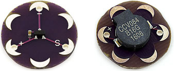
The LilyPad comes with lots of different kinds of accessories. Figure 11.4 shows the Temperature Sensor and the Vibe Board, both of which are made by SparkFun.
Figure 11.4. LilyPad Temperature Sensor and LilyPad Vibe Board from SparkFun Electronics
How you power your LilyPad project is a very important consideration. Because LilyPad projects are almost always worn or carried on the body, they don’t have an external power supply. You should give careful thought to the power requirements of your application. Consider how long you want it to last, whether it can be turned on and off, and how the power supply can be accessed and charged or changed.
Figure 11.5 shows two easy ways of powering your LilyPad. On the left is the AAA Battery Holder that holds a single AAA battery and provides an easy interface to connect to the LilyPad. On the right is the LiPo Holder that allows you to connect a lithium polymer battery with a two-pin adapter, which is the standard adapter for LiPo batteries. Because these are a part of the LilyPad series, they are both available almost anywhere that stocks LilyPad boards and components.
Figure 11.5. Two different LilyPad power boards: the AAA Battery Holder, and the LiPo Holder, which allows you to connect a lithium polymer battery

The length of time that either of these will power a LilyPad project depends on the application, which components you’re using, and how careful you are to prevent your circuits and connections from leaking current. Conductive fabric and thread can be a serious current drain if you’re not careful.
Let’s look at conductive fabric and thread and see how to use them properly.
11.1.2. Conductive thread and fabric
Your LilyPad can be connected to its circuits using wires or conductive thread. The advantage of thread is that it allows you to sew your components into the wearable itself, making a stronger bond with the fabric and the surface of the garment. The disadvantage is that conductive thread has a much higher resistance than wire, meaning that your signals will be weaker, and precise communication like I2C or SPI can be affected. Our general approach is to use insulated wires in combination with conductive thread when practical. Figure 11.6 shows some conductive ribbon and table 11.1 outlines some types of conductive thread.
Figure 11.6. Conductive ribbon

Table 11.1. Types of conductive thread
|
Name |
Resistance |
Notes |
|---|---|---|
| Shieldex sewing thread, size 33 | 40 ohms/meter | Has to be hand-sewn |
| Shieldex sewing thread, size 92 | 300 ohms/meter | Can be used in industrial sewing machines |
| Conductive ribbon | 0.3 ohm/meter | 1 mm thick Can carry three signals |
Conductive fabrics are different from conductive threads but the theory is the same: they provide a medium that you can attach to the fabric of your wearable and to which you can connect components. Extremely flexible and nearly transparent circuits can be made using conductive fabrics. Copper-based conductive fabrics can be painted or drawn on with a resistant material like Vaseline and then etched like a standard circuit board. Conductive glue or conductive thread is then used to attach the components to the fabric circuit board.
A few types of fabric, along with their resistivity, thickness, and a thoroughly unscientific assessment of their comfort level as a fabric, are listed in table 11.2. The resistance is measured as a ratio; it’s proportional to the length and inversely proportional to the width. If you have a piece that is 1 x 1 inches, then you’ll have 1 ohm resistance in either direction; a piece that is 3 x 1 inches will have 3 ohms resistance lengthwise and 0.3 ohms resistance widthwise.
Table 11.2. Types of conductive fabric
|
Name |
Resistance |
Thickness |
Comfort |
|---|---|---|---|
| Shieldex | 0.3 ohms/sq | 0.1 mm | Somewhat uncomfortable |
| MedTex 180 | < 1 ohm/sq | 0.55 mm | Fairly comfortable against the skin |
| Nickel mesh | 0.1 ohm/sq | .08 mm | Uncomfortable |
You can solder to some fabrics, though you need to be very careful when doing so.
There are also several types of conductive glues that are readily available if you don’t want to sew a component or a circuit into place. These usually hover around 300 ohms of resistance and can hold a few grams, but nothing extremely heavy or anything that will be stressed greatly. A quick search for wire glue or conductive adhesive should help you locate some options.
Adhesive or glue is good for attaching ends of components to conductive fabric or small mounting brackets, but it’s permanent, so be sure about the placement and arrangement before breaking out the glue.
Now we’ll look at building with the Arduino.
11.2. Creating a turn-signal jacket
This section shows you how to make a simple turn-signal jacket that allows the wearer to activate turn signals by pressing small flex sensors at the cuffs to turn the signals on and off. For this example, you’ll need the following:
- Two flex sensors
- A LilyPad
- Four LEDs
- Three meters of conductive thread
This project is not terribly inventive—it was done by Leah Buechley as one of the first demonstrations of how to use the LilyPad. But it’s an excellent demonstration project. In her example, Buechley used pushbutton switches, which we find slightly more difficult to use while cycling than a flex sensor. A small flex sensor, like the one pictured in figure 11.7, allows the user to easily turn the signal on and off.
Figure 11.7. Flex sensor

The flex sensor is not easy to sew into fabric, so our suggestion is to place a piece of fabric over the top of the flex sensor and sew that into the cuff of the jacket on the inside. Fabric in front of the sensor won’t affect its operation or readings at all, so it’s perfectly safe.
You can wire the jacket however you’d like, but figure 11.8 shows a wiring diagram that we’ve tested out and that has been robust so far. Figure 11.9 shows how the sensors can be attached to the jacket itself.
Figure 11.8. Connecting the LilyPad, LEDs, and flex sensors

Figure 11.9. Sewing the components into the jacket

The code for the application is quite simple (see listing 11.1). You read the analog value from the flex sensor, and if the change in the value is above a certain amount, the LEDs are lit for 10 seconds. This change in the value means that gradual pressure can be applied to the sensor without triggering it—handy for bike riding when you may brush or press against things.
Listing 11.1. TurnSignals.ino


One thought for improving the jacket might be to add a sound from a speaker or a buzz from a vibration motor to indicate to the user when the turn signals are on. Let’s move on to another project to explore attaching a small speaker to a jacket.
11.3. Creating a wearable piano
Another classic example of garment-sized wearables is a musical instrument outfit. For this example you’ll need the following:
- A LilyPad Arduino
- A 0.25 W speaker
- 10 thin pieces of copper
- 5 thin pieces of rubber foam
- Thread
We’ll examine a simple synthesizer that uses soft buttons to trigger different notes. These buttons can be attached however you’d like, but our preference is to attach them vertically at the breast-pocket level using two layers of thin copper separated by foam and encased in fabric (see figure 11.10). These can then be sewn onto the garment.
Figure 11.10. Creating a simple soft button

The example in listing 11.2 requires five buttons. It can be modified to use more or less depending on how you decide to configure your synthesizer or whether you want more or fewer notes. In the loop() method you’ll notice that some of the buttons are used in combination to trigger other notes.
Listing 11.2. WearablePiano.ino

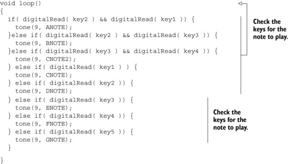
The series of if statements in the loop() method checks each button or pair of button combinations to play the eight notes. If you want to play more notes you can simply add more button combinations to check, though keep in mind that it might be hard for users to remember which button combinations create which notes.
The wiring diagram for this application is shown in figure 11.11.
Figure 11.11. Connecting the buttons and speaker to the LilyPad Arduino

To develop this further you may want to add a flex sensor or other analog input device to control how long the notes are played. You can also add a headphone jack instead of a speaker to play back the sounds, which makes the wearable more private but less enjoyable for the public.
For the next project we’ll use something smaller—the Arduino Pro Mini—to make a more-miniaturized wearable.
11.4. The Arduino Pro Mini
There’s more than one way to create a wearable, and more than one controller you can use to create one. The Arduino Pro Mini is a microcontroller board based on the ATmega328. As mentioned earlier in the chapter, there are two different versions of the Pro Mini: a lower voltage one that runs at 3.3V and 8 MHz, and a higher voltage one that runs at 5V and 16 MHz. Both versions have 14 digital input/output pins (of which 6 can be used as PWM outputs), 6 analog inputs, an onboard resonator, a reset button, and holes for mounting pin headers. A six-pin header can be connected to an FTDI cable or SparkFun breakout board to provide USB power and communication to the board.
The Arduino Pro Mini shown in figure 11.12 is intended for semi-permanent installation in objects or exhibitions, but it’s also excellent for wearables. The board comes without premounted headers, allowing you to use various types of connectors or to solder wires to it directly. The Arduino Pro Mini is designed and manufactured by SparkFun Electronics, but it’s available from hobbyist electronics shops all over the world.
Figure 11.12. The Arduino Pro Mini

The Pro Mini connects directly to the FTDI basic breakout board that you can see in figure 11.2. When the Pro Mini is used with this breakout board it supports auto-resetting after you load a new sketch to the board. It also works with the FTDI cable, but note that the FTDI cable doesn’t allow you to use the auto-reset feature.
11.5. Creating a smart headphone
One of our favorite project ideas is making a pair of headphones that pause the music on your computer when you take them off. To detect when your headphones are off we’ll use the QRE1113, which is a small IR-reflectance sensor (see figure 11.13).
Figure 11.13. The tiny QRE1113 IR-reflectance sensor

The sensor shines an IR LED out and allows you to determine how much of that light bounces back using a photo-transistor. There are four pins on the QRE1113: two control the IR-emitting LED, and the other two are the collector and emitter of a phototransistor. In the application code, you watch for a sudden change in the value returned from the QRE1113 and send a signal to the parent computer if one is received. The serial message is received by a small program that monitors the serial communication and pauses the iTunes player if any signal is received.
At its simplest, this program requires that an FTDI cable is used to connect the Arduino Pro Mini to the parent computer. For this example you’ll need the following:
- A pair of headphones
- An Arduino Pro Mini
- A QRE1113
- A computer to connect to the Arduino
The .ino file to run on the Arduino Pro Mini is shown in the next listing.
Listing 11.3. headphones.ino

Now it’s time to pause the music on the computer when receiving data from the Arduino. There are a great number of music players for computers and we can’t specify how to pause all of them, so we’ll just demonstrate iTunes on Windows and OS X. Both of these use Python, the language outlined in chapter 12.
The code for the Windows Python program is shown in the following listing.
Listing 11.4. win.py

The code for OS X looks a bit different because it uses AppleScript, a scripting language for OS X that’s included with the operating system (see the next listing).
Listing 11.5. osx.py

If you’d like to make this into a more lightweight and less intrusive program you could consider altering this project so that the Arduino communicates with the parent computer over Bluetooth using a Bluetooth module such as the Bluetooth Mate Silver shown in figure 11.14. None of the code needs to change, but you’ll need to configure the connection to the Bluetooth channel on your headphones.
Figure 11.14. A Bluetooth Mate Silver transmitter

In the next example we’re going to create a compass with a real-time readout that’s sewn into a jacket. Although you can get this functionality from a smartphone, the advantage of adding it to a garment is that it can be visible all the time without needing to pull a phone out of a pocket and start an app.
11.6. Creating a jacket with a compass
In this section we’re going to look at connecting a user display directly to the wearable and to a magnetometer. A magnetometer is an instrument used to measure the strength or direction of a magnetic field, like Earth’s magnetic field. Magnetometers can identify your orientation with respect to the North Pole in one, two, or three axes, and they’re usually precise enough for simple applications. You’ve probably used or seen one of these in a smart phone.
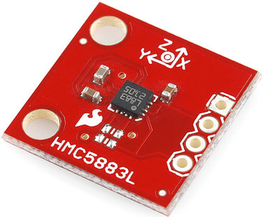
For this example we’ll use the HMC5883L created by Honeywell (see figure 11.15). These are very small, and it’s recommended that you get a breakout board to simplify connecting it to your Arduino.
Figure 11.15. The HMC5883L magnetic compass
For the readout from the magnetometer we’ll use a 7-segment serial-enabled display from SparkFun. Although a serial-enabled 7-segment display is an expensive way of creating a 7-segment display, it’s also easy to connect and simplifies construction and troubleshooting. If you’d like to, you can create your own 7-segment display and connect the controls for each segment directly to your Arduino.
The SparkFun 7-segment display draws a good amount of current and is more expensive than other options, which is a definite downside. The upside is how simple it makes the code. The SparkFun 7-segment display is shown in figure 11.16.
Figure 11.16. The SparkFun 7-segment serial display

To complete this project you’ll need the following:
- An Arduino Pro Mini
- An HMC5883L
- A 7-segment serial display
- Three meters of conductive thread
Now let’s move on to the code. The magnetometer is complex and requires a good amount of setup to initialize correctly and correct for errors and drift. All of this is done over I2C using the Wire library, which you were introduced to in chapter 9. You’ll notice a lot of register addresses in the code that will be used to initialize the different settings in the HMC5883L that you’ll be using.
Because the magnetometer communicates using I2C and the 7-segment display uses serial communication you need to use wires or conductive ribbon to ensure that the communication isn’t disturbed by the resistance of the conductive thread. Another consideration is that the 7-segment display should be visible but needs to be protected from moisture. Putting it behind a film of plastic might be advisable, though it’s not absolutely necessary.
The writemem() method in the following code listing is a simple way to send a command to the magnetometer using the Wire library and to check the value of the call to endTransmission(). This method is broken out to conserve space.
Listing 11.6. compass.ino


The preceding application is complex but its functionality is fairly straightforward: turn on the magnetometer, initialize it correctly, and compensate for the scale that it returns. Once that’s completed, the loop() method simply reads the values from the HMC5883L and writes them to the 7-segment display using the hardware serial connection on the Arduino Pro Mini. The calibration routine is necessary to ensure that the compass isn’t overly influenced by noise in the environment or its default settings.
If you’re interested in how the HMC5883L actually understands each command you can check out the datasheet for it, which is available at the Honeywell website: http://honeywell.com/.
11.7. Summary
In this chapter you learned how to use two new Arduino-compatible controllers, and also learned about an entire new range of applications for your Arduino skills. The possibilities of using microcontrollers to add computational capability to a small unobtrusive object worn on the body is one of the most exciting ways of working with the Arduino and of thinking about how to add intelligence and functionality to our lives.
You’ve seen two different Arduino-compatible boards that are small, lightweight, and easily powered by small batteries, all of which are important considerations when making a wearable. The Arduino LilyPad is larger, but it’s built specifically for attaching conductive thread and has a large community of users creating wearables. The Arduino Pro Mini is a small board that’s very lightweight, but it’s slightly more difficult to use with conductive thread, lacking the easy-to-sew eyelets of the Arduino LilyPad. It is, however, significantly smaller and provides more pins for you to use in your projects.
In the next chapter you’ll learn about connecting your Arduino to other applications written in a variety of programming languages, which will allow you to make larger and more complex projects than you would be able to with just an Arduino.