
Chapter 5. Arduino in motion
- Connecting to small DC motors
- Reverse and speed control of DC motors
- Stepper motors
- Servomotors
- Brushless motors
- Using a purpose-designed motor shield
Earlier chapters provided you with a strong foundation for using the Arduino to communicate in the digital and analog worlds. You’ve built and developed a small number of projects from start to finish that have demonstrated these principles. You’ve also explored how to use libraries and shields to extend the basic functionality of the Arduino and enable it to work with an increasingly wide range of devices.
It’s now time to consider the ways that the Arduino can be used in your own projects, whether it’s a tweeting bread oven, an internet remote-controlled robot, or an automatic cat door. This and successive chapters will give you the tools and techniques to achieve these goals.
Starting with this chapter, you’re going to look at ways of adding mobility to a project. You’ll examine different ways of controlling a variety of off-the-shelf motors or motors you may already have. Perhaps you have an old junk printer that can be stripped for its stepper motors, or old toys powered by small DC motors; these are all motors you can use!
If you want to use the Arduino to control small DC motors to power a robot, to adjust the control on an unmanned aerial vehicle with a servomotor, to step a stepper motor on a 3D printer, or to control a quadrocopter powered by brushless motors, this chapter will show you how.
Let’s get started with a look at DC motors, which are typically used to power small robots or vehicles.
5.1. Getting up to speed with DC motors
Small direct current (DC) electric motors can be found in a wide range of devices, including radio-controlled cars and boats, electric car windows, DVD players, and handheld electric fans. Many of these can be repurposed for use with an Arduino. Alternatively, new motors can be purchased from Arduino suppliers, model shops, or eBay.
Voltages for small DC motors normally range from 1.5 to 30 volts, delivered through two wires; each motor manufacturer provides a recommended voltage. Exceeding the recommended voltage by too much will cause the motor to burn out; delivering too little voltage will result in the motor not turning at all.
To make a motor reverse, you normally just need to reverse the two wires connected to it. If you’re using a motor to power a small robot, it’s often connected to a gearbox. Why a gearbox? A small DC motor normally produces high speed and low torque. A gearbox converts this to low speed, high torque, making it more suitable for powering a small robot.
A gearbox can normally be purchased with the motor. Figure 5.1 shows a typical motor with a gearbox.
Figure 5.1. A DC motor complete with gearbox from solarbotics.com

The Arduino can only provide a small amount of current—not enough to power a motor—so you’ll need to use an external power supply. You’ll use the Arduino to switch the motor on and off, as well as to provide speed control. Initially, we’ll look at switching a motor on and off, and then we’ll move on to controlling its speed.
For this section you’ll need the following items:
- A small DC motor
- An external power supply suitable for the motor
- An external power supply for the Arduino (9 volts recommended)
- A miniature relay DPDT 5 volt coil rated 2 amps or more
- A 2N2222 NPN transistor
- A 1N4003 diode
- A small breadboard
5.1.1. Stopping and starting
You start a DC motor by applying an appropriate voltage to it, and you stop it by removing that voltage. One of the simplest ways to do this is by using a switch that when switched one way starts the motor and when switched the other stops it.
You’re going to use an Arduino to turn the motor on and off, and one way to do that is to use a relay as an electrical switch. Relays are available in a number of types and packages. To switch the motor on and off, you need a type of relay called single pole double throw (SPDT), rated for a current of 2 amps or more and with a 5 volt coil.
Figure 5.2 shows the layout of an SPDT relay. A relay has a coil that, when energized by applying a voltage to it, moves the contact one way (contact 1 in figure 5.2), and when de-energized moves it the other way (contact 2 in the figure).
Figure 5.2. The elements of an SPDT relay

Note
A double pole double throw (DPDT) relay is basically two SPDT’s together on the same device. It’s easier to connect a DPDT relay on a breadboard, so that’s what you’re going to use in the following circuit.
You can’t use the Arduino to supply the 5 volts to the coil of the relay because it can’t provide enough current, so you’ll need to use a transistor to power the coil and switch the relay. The transistor you’re going to use is a general-purpose type 2N2222 NPN transistor. The transistor will be configured as a switch to turn the relay’s coil on and off.
The 2N2222 transistor is available in either a plastic or metal package and has three wires: collector, base, and emitter. Figure 5.3 shows a 2N2222 transistor in a plastic package. The transistor works as a switch by applying a small voltage to the base wire, which causes current to freely flow between the collector and the emitter.
Figure 5.3. A NPN 2N2222 transistor in a TO-92 plastic package

We’ll discuss the circuit in more detail when we come to connecting the hardware. Next we’re going to look at the sketch.
5.1.2. Sketch to turn a small DC motor on and off
In your sketch, you’re going to repeatedly switch a motor on for five seconds and then off for five seconds. The next listing shows the sketch you’ll use to stop and start your motor. Enter it into the Arduino IDE.
Listing 5.1. Sketch to turn a small DC motor on or off
int transistorBasePin = 13;

void setup()
{
  pinMode(transistorBasePin, OUTPUT);
}

void loop()
{
  digitalWrite(transistorBasePin, LOW);
  delay(5000);
  digitalWrite(transistorBasePin, HIGH);
  delay(5000);
}
The sketch works by switching on a transistor whose base is connected to digital pin 13 on the Arduino. In the next section, you’ll learn more about the hardware and how the circuit works, starting with the electronic switch.
5.1.3. Connecting the hardware
You’re going to use a transistor to operate a relay to switch a motor on and off. The transistor is a bipolar NPN 2N2222, which is a general-purpose transistor. The transistor has three legs: a base, a collector, and an emitter. Figure 5.4 shows the typical connections for a 2N2222 NPN transistor in plastic and metal packages.
Figure 5.4. A 2N2222 NPN transistor with legs connected to a TO-92 plastic package on the left and a TO-18 metal package on the right

Note
There’s no guarantee that the leg arrangement will be exactly as shown in figure 5.4. If in doubt, consult the manufacturer’s data sheet.
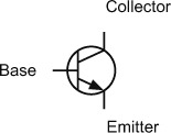
You’re using the transistor so that it acts as a switch; figure 5.5 shows the schematic symbol for an NPN transistor.
Figure 5.5. Schematic symbol for an NPN transistor showing the base, collector, and emitter
Note
There are two types of standard transistors: NPN and PNP. The letters in the acronyms refer to the layers of semiconductor materials used to make them. The majority of transistors used today are NPN, because they’re the easiest type to make.
When no voltage is applied to the base of the transistor, the switch is off. When a voltage greater than 0.6 volts above the emitter is applied to the base, the transistor switches on and current flows from the collector to the emitter. Turn off the voltage to the base, and the transistor switches off again.
Note
The transistor is never fully switched off because a small amount of leakage current is passed.
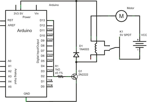
Figure 5.6 shows the complete circuit diagram for your circuit.
Figure 5.6. Schematic diagram for switching a motor on and off with a transistor and a relay
The relay you’re going to use is a DPDT; you could use an SPDT relay, but its pinouts are difficult to fit onto a breadboard. Figure 5.7 shows the pinouts for a typical DPDT relay.
Figure 5.7. Pinouts of DPDT relay

You’ll need to check the datasheet for the relay you use to identify its pinouts, but as a general rule, the coil is at one end and is spaced differently from the other pins. The common (COM) pins are closest to the coil, with the normally closed (NC) pins next and the normally open (NO) connection at the far end. Figure 5.7 shows the pinouts of the relay we used.
In the circuit diagram in figure 5.6, the D1 diode is a protection diode. When a relay coil is switched off, it can generate high voltage spikes that could potentially damage transistors and integrated circuits. The diode deals with these spikes safely, protecting the other components in the circuit.
When the Arduino sends a HIGH signal to the base of the transistor, it switches the transistor on; this in turn energizes the relay coil, which moves the contacts and completes the circuit to the motor, causing it to turn. When the Arduino sends a low signal to the transistor base, it turns it off, causing the relay coil to de-energize and move the contacts to the NC position, which breaks the motor circuit and turns it off.
Using the circuit diagram in figure 5.6 as a guide, assemble the circuit on a breadboard. Figure 5.8 shows the completed circuit.
Figure 5.8. Completed circuit controlling a motor with a relay

Having completed the circuit, you can now move on to testing it.
5.1.4. Upload and test
Once you’ve made your connections, upload your sketch to the Arduino. You should notice the motor switching on for five seconds and then switching off for five seconds in a continuous loop.
Using a transistor and relay like this is a great way to switch a motor on and off, but there are times you’ll want to be able to control the motor’s speed and direction. That’s what you’re going to do next.
5.2. Speed control and reverse
Reversing a DC motor just involves swapping the wires from the power supply to the motor. But if your motor is installed in a remote place or on a mobile robot zipping across a room, switching wires becomes more difficult.
Controlling the speed of a motor is even trickier. The speed of a motor can be varied by altering the voltage applied to it. The less voltage, the slower the motor will turn, and the more voltage, the faster the motor will turn.
Note
Running a motor at too high a voltage is likely to cause it to overheat, resulting in permanent damage.
One way to vary the voltage is to use a potentiometer to produce variable resistance. This is shown in figure 5.9.
Figure 5.9. Using a potentiometer to control the speed of a motor

This is a very simple way to control a motor, but it’s very inefficient because the potentiometer can quickly become very hot. A much more efficient way is to use a method called pulse width modulation (PWM), which we’ll discuss next.
5.2.1. PWM to the rescue
A motor is at its most efficient when its design voltage is supplied to it. PWM is the most efficient way to power a motor, and it works by applying a series of voltage pulses to the motor.
We like to use the analogy of a playground carousel: if you start a carousel spinning, it will continue to spin and gradually slow down. To keep it turning, you need to give it another spin. To make the carousel turn faster at a constant speed, you need to give it lots of small spins; fewer spins will lower the speed. In the same way, you can control a motor’s speed by switching the voltage on and off quickly.
You previously met the analogRead function, which measures an analog voltage and converts it to a digital number using the Arduino analog-to-digital converter (ADC). You would be forgiven for thinking that the Arduino analogWrite function does the opposite and outputs a voltage relative to a digital value given to it, but, in fact, the analogWrite function produces a PWM output. Figure 5.10 shows a graphical representation of the output from an Arduino using the analogWrite function.
Figure 5.10. Output from an Arduino using the analogWrite function

The Arduino produces the output as a series of pulses, which, when coupled with the correct components, make it ideal for controlling motor speed.
Note
The Arduino’s software automatically configures all of an Arduino CPU’s available timers for hardware PWM duty at the beginning of every sketch. The Arduino’s programming language makes PWM easy to use: call analogWrite(pin, duty cycle), where duty cycle is a value from 0 to 255, and pin is one of the PWM pins (3, 5, 6, 9, 10, or 11 on a standard board, or pins 2 through 13 on an Arduino Mega).
As we’ve said before, the Arduino can’t itself provide enough current to drive a motor, but you can use the Arduino to control the speed and direction of rotation. In the next section, you’re going to learn about a special circuit called an H-bridge. The H-bridge allows you to power a small DC motor and will give you more control over it than the transistor relay combination used previously.
5.2.2. The H-bridge for motor control
An H-bridge is a common way of controlling the speed and direction of a DC motor. Initially we’ll use an H-bridge to turn a motor on and off and control its direction of rotation, and then we’ll return to what we learned in the last section and use PWM to control its speed.
Figure 5.11 shows a typical circuit diagram of an H-bridge made up of four switches.
Figure 5.11. An H-bridge made up of four switches to control the direction of a motor

A good way to visualize how the circuit in figure 5.11 works is to use a table. Table 5.1 shows the motor’s action based on the position of the four switches.
Table 5.1. Motor action based on position of switches in the H-bridge shown in figure 5.11
|
S1 |
S2 |
S3 |
S4 |
Motor action |
|---|---|---|---|---|
| Closed | Open | Closed | Open | Turns clockwise |
| Open | Closed | Open | Closed | Turns counterclockwise |
| Open | Open | Open | Open | Free runs |
| Closed | Open | Open | Closed | Brakes |
| Open | Closed | Closed | Open | Brakes |
In two of the rows, the motor brakes, which is caused by the motor terminals being short-circuited. If the motor is turning, it will free-run (coast to a stop) if all the switches are open.
We could duplicate the H-bridge in figure 5.11 using transistors to replace the switches, but for ease of use and speed of assembly, you’re going to use an excellent, readily available, purpose-designed integrated circuit that has two H-bridges on it. The L293D dual H driver provides a ready means of controlling both the direction and speed of a small DC motor. It’s suitable for use in small robots or vehicles.
Note
Make sure you get the L293D, not just an L293; the L293D comes equipped with built-in protection diodes.
You’ll need the following items:
- A small DC motor
- An external power supply
- A breadboard
- An L293D dual H driver
5.2.3. The L293D dual H driver
The L293D comes in a 16-pin package with pinouts as shown in figure 5.12.
Figure 5.12. Pinouts of the L293D dual H driver
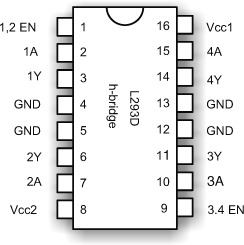
Table 5.2 provides descriptions of each of the L293D pinouts.
Table 5.2. Pinouts of L293D dual H driver
|
Pin |
Label |
Description |
|---|---|---|
| 1 | 1,2 EN | Enables half-H driver 1 and 2 |
| 2 | 1A | Half-H driver 1 input |
| 3 | 1Y | Half-H driver 1 output |
| 4, 5, 12, 13 | GND | Ground |
| 6 | 2Y | Half-H driver 2 output |
| 7 | 2A | Half-H driver 2 input |
| 8 | Vcc2 | Motor supply 4.5–36V |
| 9 | 3,4 EN | Enables half-H driver 3 and 4 |
| 10 | 3A | Half-H driver 3 input |
| 11 | 3Y | Half-H driver 3 output |
| 14 | 4Y | Half-H driver 4 output |
| 15 | 4A | Half-H driver 4 input |
| 16 | Vcc1 | 5V logic voltage |
The L293D has the following characteristics:
- Peak output current of 1.2 amps
- Continuous output current of 600 milliamps
- Voltage range of 4.5–36 volts
- Drivers enabled in pairs
- Can drive two DC motors or one stepper motor
You’re now going to look at how you can use the L293D to drive your small DC motor.
5.2.4. Connecting the hardware
Although the L293D is capable of driving two DC motors, we’re only going to show how to drive one. The same techniques are used to drive two motors, so you can easily expand this if your own project requires you to use two.
Figure 5.13 shows the circuit diagram for the connections between the motor, the H-bridge and the Arduino; figure 5.14 shows the assembled project on its breadboard.
Figure 5.13. Circuit diagram showing connections between the motor, the L293D, and the Arduino

Figure 5.14. DC motor control using an L293D integrated circuit

Note
Make sure you connect the grounds of the two power supplies together.
Once you’ve completed assembling the circuit, you can move on to constructing your sketch.
5.2.5. Sketch to control a motor with an L293D
Looking at the circuit diagram shown in figure 5.13, you can see that the motor is connected to pins 3 and 6 with pins 1, 2, and 7 connected respectively to pins D11, D4, and D7 on the Arduino. You can draw up a truth table (table 5.3) based on these connections, and use this information to write your sketch.
Table 5.3. Truth table for L293D connected to a DC motor
|
1,2 EN |
1A |
2A |
Motor |
|---|---|---|---|
| HIGH | LOW | HIGH | Turns clockwise |
| HIGH | HIGH | LOW | Turns counterclockwise |
| HIGH | LOW | LOW | Brakes |
| HIGH | HIGH | HIGH | Brakes |
| LOW | (doesn’t matter) | (doesn’t matter) | Brakes |
Looking at the table, you can see that for the motor to operate, the enable pin (1,2 EN) must be HIGH with the 1A and 2A pins controlling the direction. Armed with this information, you can now write your sketch, as shown in the next listing.
Listing 5.2. Using an L293D to control a small DC motor

Listing 5.2 shows a sketch that you can use to switch your motor on and off with the L293D H-bridge. You first set the enable pin to LOW, thereby disabling the H-bridge. During the loop, you enable the H-bridge by setting the enable pin to HIGH. The in1A and in2A pins, which are connected to pins 2 (1A) and 7 (2A) on the L293D, are changed in the loop so that the motor turns in one direction for five seconds and then the other direction for five seconds with a two-second gap in between. Let’s move on and test your sketch.
5.2.6. Upload and test
Check your connections, and then upload the sketch to the Arduino. If everything is working correctly you should observe the motor rotating one way and then the other way with a pause in between. The sequence then repeats.
We’ve just shown you how to use a circuit to control one motor; controlling another is just a matter of duplicating the circuit. By changing your code and using the same circuit, you can also alter the speed of the motor, which you’ll do next.
5.2.7. Changing motor speed
We previously talked about how PWM can be used to control the speed of a motor, and you can do the same with this circuit. You’ll use PWM on the enablePin to enable and disable the H-bridge. Here’s the new sketch.
Listing 5.3. Controlling motor speed with an L293D


This sketch is similar to the previous one; you’re using a for loop that varies the PWM output on the enablePin from 0 to 255, first rotating the motor in one direction and then the other. After either changing your existing sketch or creating a new one, you can move on to testing it.
5.2.8. Upload and test
Check over your connections, and then upload the sketch to the Arduino. If everything is working correctly, you should see the motor rotating in one direction and then the other, with the motor gradually increasing in speed from stationary to full. The sequence then repeats.
Note
You may notice a delay between each start of the motor because it may need a minimum PWM value to start turning. This depends on an individual motor’s characteristics, but is perfectly normal.
We’ve shown you how to use this circuit to control one motor, but as before, controlling another is just a matter of duplicating the circuit.
The circuit you’ve built in this example is only suitable for driving small motors. Large DC motors can be similarly controlled with PWM, but they require suitably rated components; unfortunately, these components tend to be more specialized and expensive.
This concludes our look at controlling small DC motors. Next, we’ll look at stepper motors, which can be precisely controlled
5.3. Stepper motors: one step at a time
A stepper motor is a special type of motor that can move in a series of discrete steps. Stepper motors are a good choice for projects requiring controlled and accurate movement. Typical projects include 3D printers, telescope positioning systems, and computer numerical control (CNC) lathes and mills.
Good sources for obtaining stepper motors are old inkjet or laser printers, where they’re used to move the print heads and to control paper feed. You can also purchase new ones from electronics suppliers or from eBay.
Figure 5.15 shows a typical stepper motor purchased from eBay.
Figure 5.15. A stepper motor purchased from eBay

Stepper motors are classified according to their frame size, which corresponds to the diameter of the body: a size 11 has a body diameter of 1.1 inches, and a size 23 has a body diameter of 2.3 inches. Stepper motors are also often rated in terms of the torque they can provide, with the torque being proportional to body length: the longer the body, the greater the torque. The step angle is also normally provided; a stepper motor with an angle of 9 degrees will require 40 steps to complete a full revolution.
Note
Torque is a measure of the rotational force a motor can provide, often given in ounce-inches.
There are two main types of stepper motors—bipolar and unipolar—each with its own advantages and disadvantages. Let’s take a look at the differences between them.
5.3.1. Unipolar or bipolar
Bipolar and unipolar describe the internal method of construction of a stepper motor. The two types are also controlled in slightly different ways. Table 5.4 shows the main differences.
Table 5.4. Main differences between unipolar and bipolar stepper motors
|
Unipolar |
Bipolar |
|---|---|
| Simpler to control | More efficient |
| Generally lower cost | Greater torque per unit of power |
| Five or six wire connections (can be more) | Four wire connections |
| Greater speed of rotation | |
| Simpler construction |
Note
A unipolar stepper motor can be electronically controlled in the same manner as a bipolar motor if it’s connected in a particular way.
Choosing a stepper motor can be quite involved, depending on your intended usage. For projects requiring extremely accurate high torque, choose the bipolar variant; for simpler projects, the cheaper unipolar type is a good choice, although bipolar motors are now becoming more readily available because of the reduction in cost of the integrated circuits needed to control them.
If you’re scavenging a motor from existing equipment or purchasing a motor from eBay, you’ll need to identify the type of stepper motor and which wires connect to which coil.
Let’s take a look at the steps required to identify the motor type and connections of a stepper motor we purchased from eBay.
A visual inspection revealed a label on the back, as shown in figure 5.16. This indicated that the motor has a step angle of 1.8 degrees and that it draws 0.5 amps of current. The description provided by the seller also indicated the motor was rated at 6.5 volts.
Figure 5.16. Label on the back of a stepper motor

The stepper motor has a step angle of 1.8 degrees, so we calculated the number of steps to complete one revolution by dividing 360 degrees by the step angle:
360 / 1.8 = 200
Based on our calculation, the stepper motor takes 200 steps to complete one revolution.
The motor has six wires connected to it, and based on what we already know, this identifies it as a unipolar motor. We can work out the motor connections by using a multimeter to measure the resistance between individual wires and recording the results in a table. Figure 5.17 demonstrates taking a measurement between two wires using a multimeter.
Figure 5.17. Measuring the resistance between two stepper motor wires

Draw a truth table and record the resistance between each wire, with X denoting no connection. Our truth table for our motor is shown in table 5.5.
Table 5.5. Record of resistance between stepper motor wires
|
Blue |
Green |
Yellow |
Black |
White |
||
|---|---|---|---|---|---|---|
| Red | X | 26 | X | X | X | 13 |
| Blue | 26 | X | X | X | X | 13 |
| Green | X | X | X | 13 | 26 | X |
| Yellow | X | X | 13 | X | 13 | X |
| Black | X | X | 26 | 13 | X | X |
| White | 13 | 13 | X | X | X | X |
What we’re measuring is the resistance in the coils of the stepper motor. The unipolar stepper motor has two coils, each with a wire connected halfway along the coil. Notice how some measured values are half the values of others—13 ohms instead of 26 ohms. Figure 5.18 shows this more clearly.
Figure 5.18. Resistance measured from coils of a unipolar stepper motor

Using the preceding method, we identified the coil wires of our unipolar stepper motor.
We should also take a quick look at bipolar stepper motors, because these are readily available in surplus equipment such as old printers. Figure 5.19 shows a bipolar stepper motor from an old surplus Epson printer.
Figure 5.19. A surplus bipolar stepper motor pulled from an old printer

The only identification is a label on the back of the stepper motor, as shown in figure 5.20.
Figure 5.20. Label on reverse of bipolar stepper motor

The label identifies the stepper motor as an Astrosyn P/N EM-257. A search on the internet turns up some information for its specification, which is summarized in table 5.6.
Table 5.6. Specification of surplus bipolar stepper motor
|
Specification |
Value |
|---|---|
| Voltage | 7 volts |
| Current | 0.7 amps |
| Wires | 4 |
| Steps/revolution | 200 |
| Step angle | 1.8 degrees |
| Frame size | 17 (1.7 inches) |
Like the unipolar motor, the bipolar motor has two coils. We can identify the coils using a multimeter to measure their resistance. Because there are only four wires and no center taps, we just need to find out which two wires connect together.
One of the wires has a red stripe on it. We call this wire number one, and then number the other wires sequentially. Using the multimeter we discovered that wire number one was connected to wire three, and that wire two was connected to wire four.
You’ve now seen how to identify the wires for both unipolar and bipolar stepper motors.
You now need to work out how to connect a stepper motor to the Arduino, and for this you’re going to use the L293D chip that you previously used to power your DC motor.
5.3.2. Connecting the hardware
You’ll need the following items:
- A stepper motor
- An external power supply
- A breadboard
- An L293D dual H driver
- A selection of jumper wires
- Two 2-pin screw connectors
The L293D can drive either a bipolar or a unipolar stepper motor. Figure 5.21 shows the schematic for your circuit to drive a bipolar stepper motor.
Figure 5.21. A schematic diagram using an L293D to drive a bipolar stepper motor

You use the Arduino digital pins 8 through 11 to provide the control inputs for the L293D chip. Pins 1 and 9 of the L293D are tied to the 5 volt supply so that the H-bridges are always enabled (when you controlled the DC motor, you used these pins to provide the PWM control by switching them to either HIGH or LOW).
Pin 8 on the L293D provides the power for the motor; make sure you tie the grounds for the 5 volt supply and the stepper motor supply together. One coil connects to pins 3 and 6, and the other to pins 11 and 14 of the L293D chip.
Note
The circuit diagram shown in figure 5.21 is for a bipolar stepper motor; when using a unipolar stepper motor with an L293D, connect the center tap of the coils to ground.
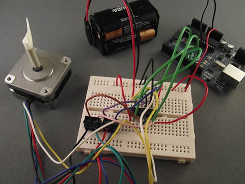
Now that you’ve studied the schematic, you can move on to assembling the circuit on a breadboard. Figure 5.22 shows the completed circuit.
Figure 5.22. Circuit connections between the L293D and the unipolar stepper motor
5.3.3. Stepper motor library functions
The Arduino IDE has excellent support for stepper motors and provides a library appropriately called Stepper that can be used with either bipolar or unipolar stepper motors. We took a brief look at the Stepper library in chapter 4 and saw that the library has three main functions that together control the speed and direction of rotation of the stepper motor. Let’s look at each of these in turn, starting with the Stepper function.
Stepper
The Stepper function has two forms depending on the circuitry used to drive your stepper motor, because it’s possible to control a stepper motor using only two pins of the Arduino by adding additional components. These are the functions:
Stepper(number_steps, pin1, pin2)
Stepper(number_steps, pin1, pin2, pin3, pin4)
The number_steps variable is the number of steps your stepper motor takes to complete one revolution, which, if you’ll recall, you can calculate by dividing 360 by the step angle. For example, if you have a motor with a step angle of 1.5 degrees, the calculation is as follows:
360 / 1.5 = 240 steps
The remaining variables—pin1, pin2, and the optional pin3 and pin4—are the Arduino digital pins that are used to control the stepper motor.
Note
In our example, we used all four pins.
setSpeed
This optional function sets the motor’s speed of rotation in revolutions per minute (RPM). This function doesn’t actually cause the stepper motor to turn, but it sets the speed at which it will turn when it’s commanded to by the steps function.
setSpeed(rpm)
steps
This function moves the motor the number of steps specified: a negative number causes the stepper motor to turn one way, and a positive number causes it to turn the other way.
steps(num_steps)
The rate at which the stepper motor moves between steps is set by the setSpeed function; if this function isn’t called in your sketch, the stepper motor will move as quickly as it’s able to between steps.
Now that you’ve seen the functions available to you, let’s look at the sketch you’re going to use to step your motor.
5.3.4. Sketch to control a stepper motor
This sketch is shipped with the Arduino IDE, and it’s a great way to ensure that you have your stepper motor wired correctly. Because it moves the motor one step at a time, the sketch is called stepper_oneStepAtATime, and it can be found in the Files > Examples > Stepper menu. We’ve provided a copy of it in the following listing.
Listing 5.4. Sketch to drive a stepper motor

The first line of the sketch loads the Stepper library; you need to do this because even though the library is provided as
part of the Arduino IDE, it isn’t part of the core libraries ![]() . You next set the number of steps for your stepper motor; this listing is set for a 200-step motor, but yours may be different
. You next set the number of steps for your stepper motor; this listing is set for a 200-step motor, but yours may be different
![]() . You next make a call to set up your Stepper object and set the pin numbers to use.
. You next make a call to set up your Stepper object and set the pin numbers to use.
During the setup function, you set up the serial port so that you can see the number of steps taken.
In the loop function, the stepper motor is moved one step at a time, and the number of steps is sent as output to the serial port. The stepCount is incremented by 1, and then a delay of 500 milliseconds occurs before you go through the loop and step the motor again.
Take some time to make sure you understand the code in the sketch before moving on to test it.
5.3.5. Upload and test
Check over your connections and upload the sketch to the Arduino. Make sure everything is powered correctly, and hopefully the stepper motor turns one step at a time.
If it doesn’t turn, you may need to switch the wires going to the coils—these must be configured correctly for the sketch to work. Remove the power to the Arduino, swap the wires, and try again. You might need to make a couple of wire swaps to get everything connected correctly and get the stepper motor turning one step at a time.
In this section on stepper motors, we’ve covered both unipolar and bipolar stepper motors and how to connect them correctly to your L293D chip. You now have a working stepper motor that you can use in any future projects. Next, we’re going to take a look at another type of motor, called a servomotor.
5.4. Try not to get in a flap with servomotors
Servomotors are very common in the model-control world and are excellent for moving flaps on model airplanes or rudders on model boats, and for steering model cars or robots. They’re also widely available from a number of suppliers.
A servomotor is a geared motor that can be set to turn to an angle, usually between 0 and 180 degrees, and is normally powered by a voltage of approximately 4.8 volts. Because of their low cost and their simplicity of control, they’re ideal for use in a wide variety of projects that require accurate movement. We’ve previously used a servomotor to scan an ultrasonic module from side to side to locate objects in a small robot’s path.
A typical servomotor is shown in figure 5.23.
Figure 5.23. A typical small servomotor

Let’s take a look at how a servomotor is controlled.
5.4.1. Controlling a servomotor
A servomotor has three connections to it: ground, power, and a control or signal connection. The majority of modern servo connectors have the center connector as the power line.
The control or signal connection controls the angle the servomotor turns to by sending a pulse. The pulse width tells the motor to turn to an angle somewhere between 0 and 180 degrees. The pulse has to be repeated every 20 milliseconds or the motor will return to an arbitrary position. Figure 5.24 shows the relationship between pulse width and servo angle.
Figure 5.24. Relationship between pulse width and servo angle
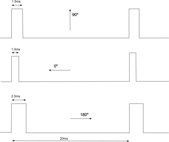
As you can see in figure 5.24, the neutral position for a servo is 90 degrees, which is obtained with a pulse width of 1.5 milliseconds. The pulse width ranges roughly between 1.0 milliseconds and 2.0 milliseconds, with the servomotor angle being 0 degrees for the former and 180 degrees for the latter.
Now that you’ve seen what is required to power and set the angle for a servomotor, let’s look at what the Arduino IDE provides.
5.4.2. Servomotor functions and methods
Just as it does for the stepper motor, the Arduino IDE ships with a Servo library to help you control a servomotor. In fact, the library gives you the ability to control up to 12 servomotors on a standard Arduino and a whopping 48 on the Arduino Mega.
The functions and methods provided by the Servo library are listed in table 5.7.
Table 5.7. Servo library functions
|
Function name |
Usage |
Description |
|---|---|---|
| Servo | Servo myServo | Creates a servo object to control a servomotor. |
| attach() | attach(pin) attach(pin, min, max) |
pin is the Arduino pin that the servomotor is attached to; min and max are values in microseconds for the maximum and minimum values of the pulse width. The defaults are minimum 544 and maximum 2400. |
| write() | write(angle) | Sets the angle of rotation for the servo-motor to turn to in degrees. |
| writeMicroseconds() | writeMicroseconds (pulse_width) | Sets the servomotor’s pulse width in microseconds. |
| read() | read() | Returns the last written pulse width angle as degrees, from 0 to 180. |
| readMicroseconds() | readMicroseconds() | Returns the last written pulse width angle in microseconds. |
| attached() | attached() | Returns true if servo is attached. |
| detach() | detach() | Stops attached servomotor from pulsing pin. |
Note
Using the Servo library disables analogWrite on pins 9 and 10 for a standard Arduino. On the Mega, using more than 12 servos will disable analogWrite on pins 11 and 12.
Let’s look at a sketch you can use with a servomotor.
5.4.3. Sketch to control a servomotor
The sketch you’re going to use is one that’s shipped with the Arduino IDE and shows the range of motion of a servomotor. The sketch is called sweep, and it can be located in the IDE under Files > Examples > Servo.
Listing 5.5. Sketch to rotate a servomotor between 0 and 180 degrees
#include <Servo.h>

Servo myservo;
int pos = 0;

void setup()
{
  myservo.attach(9);
}

void loop()
{
  for(pos = 0; pos < 180; pos += 1)
  {
    myservo.write(pos); delay(15); }
  for(pos = 180; pos>=1; pos-=1)
  {
    myservo.write(pos); delay(15); }
}
You first need to include the Servo library because although the library ships with the Arduino IDE, it isn’t included in the core functions. You next create a servo object.
In setup you attach the servo to digital pin 9 on the Arduino.
In the main loop, the code sweeps the servomotor from 0 to 180 degrees with a 15-millisecond delay between each new position to give the servomotor time to move to the new angle. The servomotor is then swept the other way from 180 to 0 degrees, again with a 15-millisecond delay between each move. The loop then repeats the process.
Let’s now move on and connect the Arduino to a servomotor so you can see the sketch in action.
5.4.4. Connecting the hardware
You’ll need the following items:
- A servomotor
- An external power supply
- A breadboard
- A selection of jumper wires
- A section of 0.1-inch header
A servomotor usually has three connections, with the center connector typically being the power connector. The other two connections are the ground and signal connections. The ground is normally black or brown, although this can vary among manufacturers.
Because you’re just using one servomotor, you can use the 5 volt supply on the Arduino to provide power, although we recommend powering the Arduino with an external power supply and not just using the USB connection.
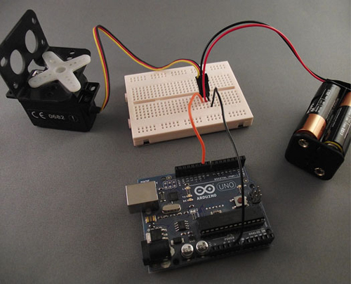
Figure 5.25 shows the section of single-row header 0.1-inch pitch we used on the breadboard to make it easier to connect to a servomotor. Figure 5.26 shows the connected circuit.
Figure 5.25. Section of single-row header 0.1-inch pitch to connect servomotor to breadboard

Figure 5.26. Connections between servomotor and Arduino
Having connected the servomotor to the Arduino, it’s time to try out your sketch.
5.4.5. Upload and test
Check your connections and upload the sketch from listing 5.5 to the Arduino. You should observe the servomotor turning smoothly from 0 to 180 degrees and from 180 back to 0 degrees. If the motor doesn’t turn, check the ground and signal connections and try again.
We’re now going to look at another type of DC motor called a brushless motor.
5.5. Mighty power comes in small packages with brushless DC motors
The humble DC motor has been around for more than a century, and the brushless motor is the new kid on the block. Mass production has rapidly brought the price down on these highly efficient motors, but what advantages and disadvantages do they have over their older cousins?
5.5.1. Why go brushless
Brushless motors provide more torque per weight, are more efficient, offer increased reliability, and have reduced electrical noise compared to standard DC motors. A disadvantage is that they require a more specialized controller than a standard motor does, although you’ll soon see how, with the correct electronics package, they’re easy to control and even allow you to use some existing code.
Brushless motors are often labeled with a value of Kv, which is the theoretical RPM per volt that a motor can rotate at. Consider a motor labeled 2400 Kv as an example. If you’re supplying 6 volts, the maximum speed the motor could turn at would be 6 x 2400 = 14,400 RPM.
Brushless motors come in two types: inrunner and outrunner. With an inrunner motor, only the inner shaft rotates; with an outrunner motor, the outer shell, or can, rotates as well. Inrunners tend to have a higher Kv and less torque, whereas outrunners tend to be lower Kv and higher torque. Figure 5.27 shows examples of both types.
Figure 5.27. An outrunner (top) and an inrunner (bottom) brushless motor

Inrunner motors tend to be used in model cars and boats, so they’re probably a good choice for any land-based vehicles or projects. Outrunner motors are normally found in model airplanes and helicopters. They’re a good choice if you want to build a quadrocopter. We’ve used outrunner motors previously in an underwater robot because of their better torque.
This completes our overview of these small and powerful motors. Let’s take a look at how you control them.
5.5.2. Gaining control
Brushless motors require specialized controllers because they’re really three-phase motors. Luckily, electronic speed controllers (ESCs) are readily available in the model radio-control world at reasonable prices and have a range of functions that you can take advantage of.
When choosing a brushless ESC, make sure that it will work with your chosen motor, because current load and voltage requirements can vary significantly from one motor to another. ESCs designed for use in model aircraft and some boats are normally only able to control the speed of rotation of a motor but can’t reverse a motor’s direction of rotation.
Caution
It’s possible to reverse the direction of a brushless motor by switching any two of the three connecting wires with each other. Don’t reverse the connections from the battery to the controller, because you’ll destroy the ESC and may also cause damage to the motor or battery pack.
ESCs designed for use in model cars and some boats are usually able to control both a motor’s speed and its direction of rotation, but make sure you check this before purchasing.
To power a brushless motor, you need to use batteries designed to take the high current required by these motors. These can be NiCd, NiMH, or the newer lithium polymore (LiPo) battery packs.
Note
Specialized chargers are needed to charge these batteries; using incorrect equipment, particularly with LiPos, can cause them to explode.
One of the great things about ESCs is that they can be controlled in exactly the same way as servomotors; this means you can use the Servo library and the things you learned in the last section to control them. Just like servomotors, they expect a pulse every 20 milliseconds with a width of between 1.0 and 2.0 milliseconds, with 1.0 millisecond being the slowest speed and 2.0 milliseconds being the highest. With ESCs that can reverse direction, the pulse range will be different: a width of 1.5 milliseconds will cause the motor to stop, a 2.0-millisecond pulse width will be the fastest forward speed, and a 1.0 millisecond pulse width will be the fastest reverse speed.
When a motor and its controller are first powered on, the motor won’t instantly start—this is a safety feature—but it will wait a period of time and may expect a particular pulse width before starting. You’ll need to consult the ESC’s manual to see if this is the case. The first brushless motor we used expected a 1.0-millisecond pulse width for a period of one second before it would function correctly.
Note
You’ll often hear a series of tones when an ESC and its motor are first powered up; this is all part of the normal startup process and can even sound quite musical.
Now that you have a basic understanding of how to control a brushless motor, let’s move on and look at some code in a sketch.
5.5.3. Sketch to control a brushless motor
Take a look at the next listing. You should recognize the code because it’s almost the same as the code in listing 5.5, with the addition of a start pulse during setup to allow the ESC and motor to stabilize.
Listing 5.6. Sketch to control a brushless motor in one direction
#include <Servo.h>

Servo myservo;
int pos = 0;

void setup()
{
  myservo.attach(9);
  myservo.write(pos);
  delay(1000);
}

void loop()
{
  for(pos = 0; pos < 180; pos += 1)
  {
    myservo.write(pos);
    delay(15);
}
  for(pos = 180; pos>=1; pos-=1)
  {
    myservo.write(pos); delay(15); }
}
The code shown in listing 5.6 is for use with an ESC that only controls speed, not direction. The next listing shows a sketch you can use with an ESC that can control a motor’s speed as well as its direction of rotation.
Listing 5.7. Sketch to use with ESC that can control speed and direction
#include <Servo.h>

Servo myservo;
int pos = 90;

void setup()
{
  myservo.attach(9);
  myservo.write(pos);
  delay(1000);

}

void loop()
{
  for(pos = 90; pos < 180; pos += 1)
  {
    myservo.write(pos);
    delay(15);
}
  for(pos = 180; pos>=90; pos-=1)
  {
    myservo.write(pos);
    delay(15); }
}
Once you’ve typed in the sketch that’s applicable to your type of ESC and motor, you can build your circuit.
5.5.4. Connecting the hardware
You’ll need the following items:
- A brushless motor
- A brushless ESC
- An external power supply for the motor
- A selection of jumper wires
For this example, we used an inrunner brushless motor with an ESC that can control both speed and direction. We also used a NiCd battery pack to supply power to the ESC.
Tip
You’ll need to connect the motor to something quite solid because these motors are very powerful when rotating.
There’s a servo-type connector connected to the ESC, and this can be connected to your breadboard in the same manner as in the previous section on servomotors. Figure 5.28 shows the completed setup.
Figure 5.28. Brushless motor controlled by an Arduino

When you’ve completed your connections, you can move on and test your circuit.
5.5.5. Upload and test
Upload your sketch to the Arduino before connecting the power pack to the ESC. Once the sketch has uploaded, connect the power pack to the ESC and reset the Arduino. After a short delay, you should observe the motor speeding up and then slowing down.
Once you’ve completed this part, it’s time to control the direction of rotation as well as speed.
5.5.6. Reverse
To control the direction as well as the speed of a brushless motor requires an ESC that’s normally found in radio-control model cars and some boats. Controlling them still involves treating the control as a type of servo, but instead of the 1.5-millisecond pulse width being the midrange speed, it’s the motor’s off position. The 2.0-millisecond pulse width is now the full forward direction, and the 1.0-millisecond pulse width is the full reverse position. You need to change your sketch to reflect this.
5.5.7. Sketch to reverse a brushless motor
The new sketch is shown in the following listing. It’s similar to listing 5.7, with a few additions.
Listing 5.8. Sketch to control a brushless motor in both forward and reverse


The sketch has a delay in setup to allow the ESC to stabilize.
During the loop, you use a for loop to increment the servo position up to a maximum of 180 and then another for loop to decrement it to 90. Another for loop decrements the servo position from 90 to 0 before a final for loop increments the servo position from 0 to 90. The delays allow the motor to stabilize between commands.
Let’s move on now and construct the circuit.
5.5.8. Connecting the hardware
We’re going to use the inrunner motor and controller from before, so you quickly test your new sketch.
5.5.9. Upload and test
Upload your sketch to the Arduino before connecting the power pack to the ESC. Once the sketch has uploaded, connect the power pack to the ESC and reset the Arduino. After a short delay, you should observe the motor speeding up and then slowing down, then doing the same in the reverse direction.
We’ll finish this chapter off by discussing a motor control shield that can be used when you want to control more than one motor.
5.6. The motor control shield for more motors
There are a few different motor control shields available; we’re going to look at one from Adafruit Industries. The shield is reasonably priced and is supplied as a kit that you assemble yourself. Figure 5.29 shows the components supplied in the kit.
Figure 5.29. Components supplied in the Adafruit Industries motor control shield kit

The shield is ideal if you want to control more than one stepper motor or a couple of DC motors. The shield is based on the L293D integrated circuit that you’ve been using in this chapter, but instead of one, it uses two of them. The shield can drive up to four DC motors or two stepper motors or servomotors, making it very versatile.
The assembled shield is shown in figure 5.30.
Figure 5.30. The fully-assembled motor controller shield

This kit is available from a number of suppliers, and it’s a great addition to your toolbox if you want to control more than a couple of motors at a time. It would be ideal for obstacle-avoidance robots where DC motors provide the motion and a servomotor controls an ultrasonic module that looks out for obstacles.
5.7. Summary
In this chapter you’ve looked at a variety of different motors and have seen which types of projects they would be suitable for and how you can control them using an Arduino and a handful of components.
You started with a small DC motor that can be used to power a wide range of robotic vehicles, and you learned how to control both its speed and direction using an L293D integrated circuit.
You then investigated stepper motors that can be accurately and precisely controlled and are used in CNC mills, lathes, and 3D printers. You learned how to identify the different types of commonly available stepper motors and then learned how to control them using the Stepper library shipped with the Arduino IDE.
Next, you learned about servomotors, which are commonly used in radio-controlled models. These small, powerful, geared motors are great in projects requiring accurate movement, like moving an ultrasonic transducer on an obstacle-avoidance robot. You used the Servo library that lets you control up to 12 servomotors on a standard Arduino, and for those more ambitious projects, up to 48 on an Arduino Mega.
You then applied what you learned about servomotors to control brushless motors. These highly efficient powerhouses are suitable for a wide range of projects, including quadrocopters and remote-piloted drones.
We ended the chapter with a brief look at a motor controller shield kit from Adafruit that’s capable of controlling up to four DC motors or two stepper motors or servomotors.
In chapter 6, you’re going to look at using ultrasonic and infrared sensors with an Arduino and see how they can be used for object detection.