
Chapter 13. Software integration
This chapter covers
- Using serial ports to communicate with applications
- Connecting an Arduino board to a Processing application
- Connecting an Arduino board to a Python application
The Arduino is a potent tool on its own, but it becomes all the more powerful when you connect it to a full-featured computer, like a laptop or a desktop computer. In fact, you do this whenever you connect the Arduino to your computer with a USB cable to upload code from the Arduino IDE to your Arduino board. The reason you take this step when you’re programming the Arduino is to take advantage of the power of your desktop or laptop to compile your code and run the Arduino IDE.
You may be thinking of the other powerful things your desktop computer can do that your Arduino can’t: computer vision, audio synthesis, network communications, and so on. But your computer is unmistakably a computer, and that’s the advantage of the Arduino: it allows you to create a new interface to your computer that doesn’t need to look or feel computer-like.
You can set up an Arduino and another computer to speak to one another using serial communication, sometimes called RS232. You’ve seen it in action if you’ve used the Serial.print() method to send messages from the Arduino to the Arduino IDE for debugging. But the Arduino IDE isn’t the only device that can receive messages from and send them to your Arduino. In this chapter, we’ll show you how your Arduino can communicate with several different programming platforms on a desktop computer to make new interfaces between your computer and your Arduino.
13.1. The serial channel
You’ve already used the serial channel to send debugging messages to the Arduino IDE using the Serial.print() method. Lots of devices other than the Arduino use serial communication to communicate with a parent computer: Bluetooth-enabled devices, GPS sensors, older printers and mice, barcode scanners, and, of course, the Arduino board. As a communication protocol, it’s rather low-level and can be quite simple or quite complex, depending on what you need from it.
Connecting the Arduino to a computer with a USB cable announces to your computer’s operating system that you’ve connected a serial device. When you install the Arduino IDE, you also install several drivers that allow the Arduino to be recognized as a device that communicates over a serial connection. Once your computer’s operating system recognizes the Arduino any programming language can be set up to listen and send data over the serial channel.
The important thing to remember is that, as with the Arduino IDE, the program listening on your computer needs to be communicating at the same baud rate as your Arduino. If your Arduino is using 9,600 the program on your computer needs to be set the same way. Another element you need to consider is that the 9,600 may be acceptable for some purposes, but for an application that requires faster communication between your controllers and your computer you might want to use a faster baud rate.
When the serial channel is set up at 9,600 bps 12 bytes of data takes about 1/100 sec. to transfer. The fastest transfer rate currently is 115,200 bps, which means those same 12 bits take about 1/1000 sec., which works out to a rate of 1 kHz. This rate is sometimes unnecessary, but in extremely time-critical applications (tangible musical interfaces are a great example), that sort of speed can be important in creating greater fidelity for the person using your application.
Once your Arduino has broadcast your message you’ll need to receive it. Most programming languages, and we do mean almost all of them, provide ways for you to send and receive messages on the serial port of the machine they’re running on. This means that anything your computer can do, you can network with your Arduino, and anything that your Arduino is capable of can be controlled or networked with your computer.
You can use several different strategies to set up serial communication between your Arduino and a computer. In the next few sections we’ll outline some of the more common strategies and look at some example code for each. First, we’ll use face tracking in Processing to control servomotors connected to an Arduino in order to ensure that a detected face stays in the center of the frame.
13.2. Servos for face tracking
Processing is one of the most influential and oldest creative code projects. Originally developed at MIT by Ben Fry and Casey Reas, it’s now maintained by a larger team. It’s written in Java, so anyone familiar with Java will understand the platform instantly. It’s also designed to be friendly to designers and artists who don’t have deep technical backgrounds so that they can begin making visual or interactive projects. It’s open source, free to download, and has versions for all the major platforms, so it’s easy to get up to speed and easy to port your projects from computer to computer or even onto the internet.
We don’t want to dig too deeply into how Processing works in this chapter, but you’ll notice a few similarities between projects in the Arduino IDE and almost all Processing applications right away. For example, the Arduino setup() and loop() methods become setup() and draw() in Processing. The IDEs look more or less the same, and the libraries are organized similarly. The two projects share a lot of history as well as a design attitude that allows for exploration and quick prototyping.
Serial communication in Processing
Processing has a library that allows serial communication, and it’s called, unsurprisingly, Serial. The following code lets you easily import this library into your project:
import processing.serial.*;
To create a serial connection you’ll want to create an instance of the Serial class:
Serial arduinoPort;
Next you need to set up the communication between the Arduino and the Processing application. In the setup() method of your application, where your application is initialized, you initialize the Serial instance:
arduinoPort = new Serial(this, "", 9600);
The constructor for the Serial class looks like this:
Serial(this, port, rate)
Let’s break this down further:
- this—The application that will run the Serial instance
- port—The name of the serial device that represents the connected Arduino
- rate—The baud rate that the communication will use
If you don’t know the name of the port off the top of your head you can call Serial.list(). It’ll return an array of the names of all devices attached to the serial ports of the computer as Strings which will allow you to easily do something like the following:
arduinoPort = new Serial(this, Serial.list()[0], 9600);
This selects the first String representing the name of a serial device. For instance, you might want to use the third serial device, so you’d pass the third item from the result of Serial.list() as the second argument to the Serial constructor:
arduinoPort = new Serial(this, Serial.list()[2], 9600);
To send a message to the serial port call the following method:
arduinoPort.write();
To read data from a serial port, you check whether there’s any data available in the serial buffer and read from it until none is left. This works because each call to read() pulls the byte out of the buffer so that it’s only read once. The buffer shrinks as you read each byte:
while(Serial.available() > 0) {
    print(arduinoPort.read());
}
Now that you’ve seen how a Processing application can interact with an Arduino you’re ready to look at a project that leverages both of these tools.
13.2.1. Assembling the face-tracking hardware
One of the things that Processing makes easy and painless is interfacing with peripheral devices, such as a camera. Reading data from a webcam attached to your computer can be a hassle in C++ or other programming languages, but in Processing it’s a breeze. The same goes for doing complex computer vision tasks like detecting faces. You might be getting some idea of where this is going: in this example we’re going to build a simple face tracker using Processing and an Arduino.
For this project you’ll need the following:
- Two servo motors
- A pan and tilt kit for the servos, or materials to make your own
- A breadboard and jump wires
- An Arduino
- A desktop or laptop computer with Processing installed on it
- A USB webcam
Let’s assemble and wire the structure that the Arduino will use to position the webcam at the center of the detected face. The basic idea is that one servomotor should control the x rotation of the servo and the other should control the y rotation of the servomotor. There are kits that allow you to do this quickly, such as the Lynx Pan and Tilt kit shown in figure 13.1.
Figure 13.1. The Lynx Pan and Tilt kit

If you don’t want to get a Lynx you can easily create a simple mount for your servomotor out of acrylic, metal, or even light wood, and then attach it to the servo disk with hot glue or screws. As long as the x-axis servo is facing upright and the y-axis servo is facing sideways you’ll have full 180-degree rotation across a hemisphere. The trick then becomes attaching the camera atop the servo that’s providing the y-axis rotation. As long as your camera is light enough any mount that provides a 90-degree angle should work. Once you have the camera in place you’re ready to position the image with signals from the Processing application.
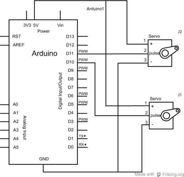
To ensure that your camera will properly track faces, make sure that the tilt motor (y-axis) is mounted at the 90-degree position of the pan motor (x-axis) and that the camera is mounted at the 90-degree position of the tilt motor. This way, the middle point of your combined servo motors will correspond to what the Processing application is sending. Figure 13.2 shows how to connect the two servos to the Arduino board. The camera will be connected directly to the computer that is running your Processing sketch.
Figure 13.2. Connecting the servomotors to the Arduino
13.2.2. Code for face-tracking
This example uses OpenCV, the most comprehensive and powerful open source computer vision library available. The OpenCV library for Processing was built by Douglas Edric Stanley and Stephane Cousot by compiling the original C++ code and then creating a Java library that can link to the Processing frameworks. This means that you can use the OpenCV library without needing to compile all the C++ code that comprises it, but it also means that the install process for this library is a little more involved than usual.
You can find the OpenCV libraries and instructions for installation at ubaa.net/shared/processing/opencv/, but here they are summarized briefly:
- Download the files for your OS.
- Run the installer.
- Move the library to the libraries folder of your Processing home folder.
You should now be ready to start working with the OpenCV libraries.
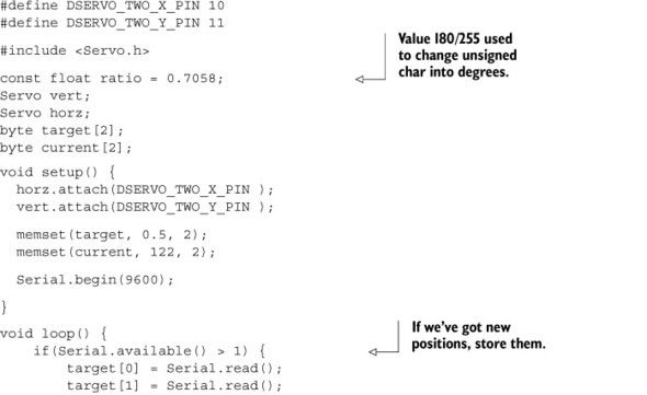
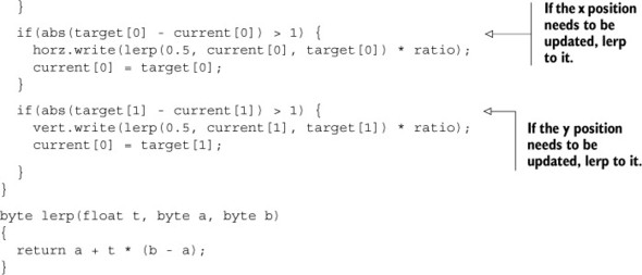
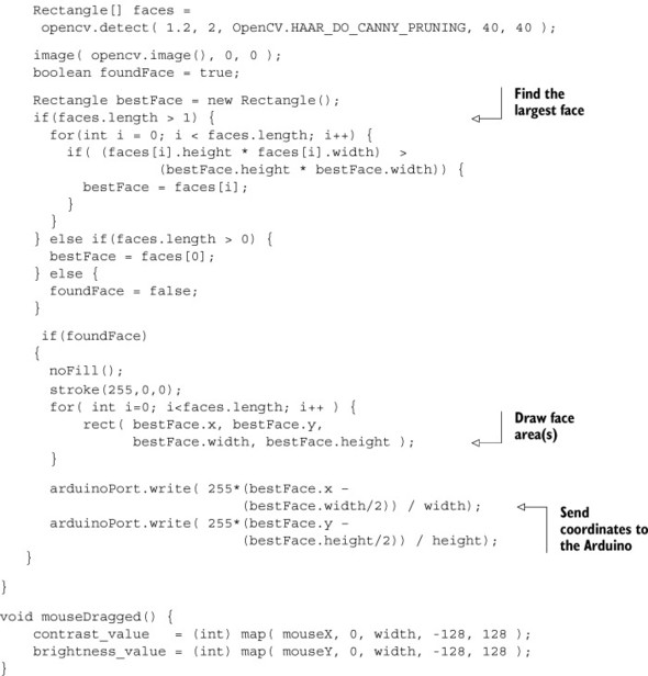
Now let’s look at the Arduino code in listing 13.1. The general idea is that the Processing application will send the coordinates for the center of the detected face to the Arduino. These are sent as normalized screen coordinates, which means it uses numbers from 0 to 1.0. The Arduino then smoothly moves the two servos toward that center. Because the camera is mounted on the servos, you don’t have to worry about centering the image in the Arduino, only moving them to the location sent from the Processing application.
Listing 13.1. Face tracking using OpenCV in Arduino
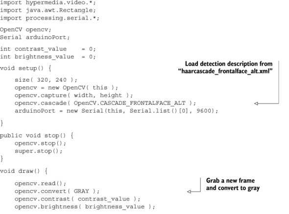
On the Processing side, there may be some strange new things in the code that you haven’t seen before, and you don’t need to understand all of it to use the face-detection functionality in OpenCV. The overview is that OpenCV can read in XML files that describe the characteristics of certain kinds of shapes: a car, a person, or a face. The data structure described in that XML file is called a Haar Cascade. By loading that XML file a data structure is created that the OpenCV library can compare each incoming frame against. If the information in the frame is a close-enough match to the XML description file, the library reports the location of the detected shape.
In this example we’ll be using a prepared XML file that describes faces. This comes with the Processing OpenCV library, so you don’t need to prepare anything extra; just add the path to it, stored in the OpenCV library as OpenCV.CASCADE_FRONTALFACE_ALT, and go.
The general flow of the Processing application is as follows:
- Start the camera.
- Read in the Haar Cascade XML file.
- Start reading in each frame from the camera.
- Convert the frame to grayscale to save on memory.
- Check for matches against the face Haar Cascade pattern.
- If a match is found send the Arduino the screen-normalized location of the face.
It sounds complex, but as you can see in the following listing the Processing code isn’t remarkably long for how powerful it is.
Listing 13.2. Face tracking in Processing
Now you have a somewhat sophisticated face-tracking system that responds to its environment and adjusts accordingly. This is only the beginning of the fun that you can have with paired servomotors and Processing. If you look around online you’ll find everything from pet toys, to home-security implementations, to practical jokes that use the same system.
13.3. Using Firmata to create an equalizer
One thing that Processing does easily that the Arduino doesn’t is audio analysis. The processor on the Arduino is just not powerful enough to analyze and extract information about audio data as it plays, but your computer is. In this example we’ll create an extremely simple equalizer display using Processing and the Arduino, running Firmata to send an analysis of the audio currently playing from an MP3 file. It’s simple but it’s fun, and it shows the basics of working with Firmata as well.
Firmata is a project initiated by Hans-Christoph Steiner that acts almost as a stripped-down operating system for the Arduino, driven completely by serial communication. You load Firmata onto your Arduino, and then from another programming language you can check the values of pins, perform complex communication with components, and set the values of pins without needing to update your Arduino code at all. You can use Firmata in Processing, openFrameworks, Cinder, Python, Ruby, Pd, and several other programming platforms.
13.3.1. Using Firmata in your application
First we’ll go over the simple part so you can see how similar using Firmata in Processing is to programming the Arduino.
If you load Firmata onto your Arduino and then want to set digital pin 12 to HIGH from a Processing application, you’d simply create an instance of the Arduino class (in this case named arduino) and then call the digitalWrite() method:
arduino.digitalWrite(12, Arduino.HIGH);
To read values you simply use the methods analogRead() or digitalRead(), passing the appropriate pin numbers as parameters.
These methods are properties of the Arduino instance that you create, so the method calls are always going to look like the following:
int an1Value = arduino.analogRead(1);
or:
int dg13Value = arduino.digitalRead(13);
Firmata requires that you set the digital pins that you want to use to be output or input pins. This is similar to what you do when you write a sketch for the Arduino using the Arduino IDE, except that, again, you’re calling the methods on the Arduino object in Processing.
Now we’re getting to the slightly harder part: how do you make an Arduino object that your Processing application can use to do all this stuff on the Arduino? The trick is to construct an instance of the Arduino class and pass in all the appropriate data when the object is created. Here’s the constructor:
Arduino(parent, name, rate)
In this constructor parent is always the Processing application that’s going to use the Arduino instance. name is the serial device that you want to connect to, and it’s something like COM1 on Windows or /dev/tty.usbmodem411 on OS X or Linux. Finally, rate is the baud rate that you want to communicate with the Arduino at. By default the Firmata library is set up to use the fastest baud rate available, 115,200, so unless you’ve changed that in the Firmata library you’ll want to use the default.
A complete constructor call will look something like this:
Arduino arduino = new Arduino(this, "/dev/tty.usbmodem411", 115200);
You’ll typically want to do this in the setup() method of your Processing application, or in the initialization of whatever other application you’re using. Once you’ve created an instance of the Arduino you can begin sending and receiving information from the Arduino itself.
Firmata also allows you to read and write over the I2C protocol, as well as control servomotors and query the state of all the digital pins on the Arduino. While it’s somewhat limited at this time (SPI or pulseIn/pulseOut aren’t currently supported), Firmata does allow you to control your Arduino from a host computer with a minimum of configuration and a great deal of control.
13.3.2. Audio analysis in Processing
First let’s look at the audio analysis we’re going to do. When you want to figure out how loud different frequency ranges in audio data are, most commonly you’ll use what’s called a fast Fourier transform (FFT). This is a technique that maps the raw numbers of audio data to the audible frequency spectrum and provides that data in an array representing the volumes in a given range of frequencies. Anyone who’s ever seen an equalizer will have an intuitive sense of what this looks like. The spectrum does not represent individual frequencies, but frequency bands centered on particular frequencies.
To do this FFT in Processing we’ll use Minim, an audio library that uses the Java Sound API, a bit of Tritonus, and JavaZOOM’s MP3SPI. This audio library is easy for people developing in the Processing environment to use. The underlying philosophy of Minim is to make integrating audio into a Processing application as simple as possible while still providing computational power to do real-time audio processing.
Minim comes installed with Processing so you don’t need to do anything to start using it, other than to add the import statement to the top of your application.
13.3.3. Assembling the equalizer hardware
This example will not have any Arduino code, because you’ll be loading the Firmata library onto the Arduino and then allowing that to handle all the communication with the Processing application. But you’ll need a few simple hardware components:
- Five LEDs
- Five 4.7k resistors
- An Arduino
- A computer with Processing installed
Figure 13.3 shows how to connect the LEDs and resistors to the Arduino to create the equalizer.
Figure 13.3. Connecting the LEDs to create your Arduino equalizer

This application is simple on the Arduino side: the data from the processed audio file is used to illuminate five LEDs that are attached to the PWM pins of the Arduino. You’ll want to attach resistors to those LEDs to ensure that they don’t burn out, but nothing else is required to see your song.
13.3.4. Code for the equalizer
You probably have Firmata already included with your Arduino IDE distribution because it’s been an included library since Arduino 0012. You should only need to load the StandardFirmata program from Examples > Firmata onto your Arduino (see figure 13.4).
Figure 13.4. Selecting the StandardFirmata program

As we mentioned earlier, the Processing library that this example uses to analyze the audio is called Minim, and it comes standard with the Processing library. You just need to import the library into the program using the import statement. A library for Firmata, called Arduino, also comes standard with Processing and is imported with the following statement:
import cc.arduino.*;
This Processing program (see listing 13.3) loads an MP3 file generically called song.mp3 and begins playing it in a loop. (You’ll need to name an MP3 file “song.mp3” and add it to the folder for your Processing sketch.) The program then creates an FFT object that can break the audio data from the song into frequency bins.
In the loop() of the application, the FFT forward() method is passed the mixed data from the audio file’s left and right channels. The resulting array is then grouped into five frequency ranges—one for each LED that you have attached to the Arduino—and it’s then sent to Firmata on the Arduino using the analogWrite() method. This calls the analogWrite() method within the Arduino and brightens or dims the LEDs depending on the strength of the averaged values for the chunk of the frequency spectrum.
Listing 13.3. Using Firmata in Processing


That’s only the beginning of what Firmata can do. It allows you to easily control an Arduino and keep your control code in the application running on your computer, rather than needing to update your code on the Arduino every time you make a change to your program. For rapid prototyping this is a real advantage, because you can concentrate on your computer program and let your Arduino act like an input or output device. To learn more about Processing I highly recommend Processing: A Programming Handbook for Visual Designers and Artists by Ben Fry and Casey Reas (MIT Press, 2007), or Processing for Visual Artists by Andrew Glassner (A.K. Peters, 2010).
13.4. Using Pure Data to create a synthesizer
Pure Data, often referred to as Pd, is a graphical programming environment intended primarily for creating real-time audio and video applications. It’s called “real-time” because you can edit your programs as they’re running without needing to stop and recompile them as you would need to with Processing or with an Arduino board. Simply making changes in the IDE updates your program as it’s running. Pd is completely free software, and there are versions for Windows, Linux, and OS X, as well as other less-common operating systems.
Because Pd is a graphical, patch-based environment rather than a text-based programming environment, completed code looks different than Arduino code. For instance, figure 13.5 shows a program or “patch” that creates the classic additive synth sound. Figure 13.5 shows what subtractive synth looks like in Pd.
Figure 13.5. A Pd patch

Luckily, though, you can paste a patch in text format into the editor and have the editor turn it into the graphical patch layout in figure 13.5.
To bring input from a serial device into your Pd patch, you create an object called a comport, which is short for “communication port.” Figure 13.6 shows what it looks like.
Figure 13.6. The comport object
![]()
The 9600 is a parameter passed to the comport, and it sets the baud rate that the patch will be listening at. If you want to use this to read from or write to your Arduino it should match the baud rate that your Arduino is sending or reading at.
There’s another object that you need to get access to the serial ports on your computer, though: the devices object. Figure 13.7 shows the devices object connected to the comport.
Figure 13.7. Connecting the comport to the devices object

Clicking on the devices object in your PD sketch shows you all of the serial devices that are attached to the computer that Pd can read in. Now it’s time to put the power of Pd to work by generating audio in response to tangible input.
13.4.1. Assembling the synthesizer hardware
The example you’ll explore in this section demonstrates one of the most powerful features of Pd: the ability to easily generate and combine multiple sounds at once with extremely fine-grained control. One of the challenges of making sounds using computers is creating expressive and intuitive interfaces so that people can have both fine-grained control and quick reaction times. A quick survey of some of the favored controls for musical instruments would put the potentiometer somewhere near the top of the list, so in this example we’ll use five potentiometers to control four oscillating sine waves. There are much more complex and expressive things you can do with Pd, but this is a good introduction not only to how communication between an Arduino and Pd works, but to some of the components of Pd as well.
For this example, you’ll need the following:
- Four potentiometers
- A breadboard
- An Arduino
- A computer with Pd installed
The wiring schematic in figure 13.8 should be quite straightforward.
Figure 13.8. Connecting potentiometers for the mixer

13.4.2. Code for the synthesizer
The Pd code is a little strange to look at the first time. You won’t see any function declarations, variable types, or curly brackets. But you do have objects, they still have properties, and there is a flow of logic you can follow.
The first thing to realize about Pd is that everything is a flow of data from one component to the next. In our case, the data comes from the Arduino, and it’s passed to a parser, then to four oscillators, and finally to the sound card. In the Pd IDE the program looks like figure 13.9.
As text, the program looks like what you see in the following listing.
Figure 13.9. The Pd patch in the Pd IDE

Listing 13.4. Pd application as text (AIA13_4.pd)
#N canvas 892 52 463 519 10;
#X obj 110 92 comport 0 115200;
#X msg 174 65 close;
#N canvas 194 45 687 494 parse 0;
#X obj 140 122 select 13 10;
#X obj 142 186 repack 22;
#X obj 137 32 inlet;
#X obj 97 390 outlet;
#X obj 142 219 route 48 49 50 51;
#X text 207 47 Comport spits out ASCII strings: potPin id , val , carriage
     return , newline.;
#X text 230 119 strip off return and bang on each newline;
#X text 211 184 repack;
#X text 266 219 route by ID;
#X text 503 296 ASCII to float;
#X obj 213 298 string2any 16;
#X obj 96 299 string2any 16;
#X obj 310 297 string2any 16;
#X obj 405 297 string2any 16;
#X obj 405 389 outlet;
#X obj 310 389 outlet;
#X obj 213 390 outlet;
#X connect 0 0 1 0;
#X connect 0 2 1 0;
#X connect 1 0 4 0;
#X connect 2 0 0 0;
#X connect 4 0 10 0;
#X connect 4 1 11 0;
#X connect 4 2 12 0;
#X connect 4 3 13 0;
#X connect 10 0 16 0;
#X connect 11 0 3 0;
#X connect 12 0 15 0;
#X connect 13 0 14 0;
#X restore 110 135 pd parse;
#X text 78 16 Your port here;
#X msg 83 64 open $1;
#X obj 80 40 hradio 15 1 0 8 empty empty empty 0 -8 0 10 -262144 -1
-1 1;
#X obj 118 319 dac~;
#X obj 112 188 osc~;
#X obj 36 188 osc~;
#X obj 190 188 osc~;
#X obj 264 188 osc~;
#X obj 115 266 *~ 0.25;
#X connect 0 0 2 0;
#X connect 1 0 0 0;
#X connect 2 0 8 0;
#X connect 2 1 7 0;
#X connect 2 2 9 0;
#X connect 2 3 10 0;
#X connect 4 0 0 0;
#X connect 5 0 4 0;
#X connect 7 0 11 0;
#X connect 8 0 11 0;
#X connect 9 0 11 0;
#X connect 10 0 11 0;
#X connect 11 0 6 0;
#X connect 11 0 6 1;
On the Arduino side we’ll attach four potentiometers to control each of the oscillators on the Pd side, and then we’ll read the values from each of them, as shown in the next listing.
Listing 13.5. Application to communicate with Pd
float val1,val2,val3,val4;

int potPin1 = 0;
int potPin2 = 1;
int potPin3 = 3;
int potPin4 = 4;

void setup()
{

  Serial.begin(115200);
}

void loop()
{

  val1 = analogRead(potPin1);
  Serial.print(potPin1);
  Serial.println(map(val1, 0, 1024, 200, 1000),DEC);

  val2 = analogRead(potPin2);
  Serial.print(potPin2);
  Serial.println(map(val2, 0, 1024, 200, 1000),DEC);

  val3 = analogRead(potPin3);
  Serial.print(potPin3);
  Serial.println(map(val3, 0, 1024, 200, 1000),DEC);

  val4 = analogRead(potPin4);
  Serial.print(potPin4);
  Serial.println(map(val4, 0, 1024, 200, 1000), DEC);

}
There’s not much to the Arduino side, but combined with the Pd application it allows you to create a rich range of sounds that can be closely tuned by the Arduino. Note that the data sent over the serial port is mapped between 200 and 1000, which ensures that the frequency of the sine wave is a little more palatable.
Using the Arduino with Pd is powerful because it allows musicians and DJs to create their own tangible interfaces to Pd and to their music. This means that you can not only recreate interfaces that you may be familiar with, but also experiment with new ways of physically inputting data and creating music.
To learn more about Pd I recommend that you look at the Pd tutorial site at www.pd-tutorial.com.
13.5. Using Python to monitor temperatures
Python is one of the most popular programming languages—it’s flexible, powerful, and accessible. It has a remarkable number of libraries for doing everything from game development to applied mathematics to website development. It’s been under constant development since 2001 and has steadily grown in popularity and capability over the years.
The example we’ll explore in this section revolves around a simple idea: what is the temperature in discrete parts of a home at any given time? You could walk around with a thermometer and figure this out, but it might be more fun and more practical to place several thermometers around the house and send the temperature data as email messages to your own email account. This example has the Arduino sleep until it’s time to wake up (to save on power or battery), and upon waking, send a message to the Python program. Once the Python application has received a message it parses it by room and then emails it off.
One thing to note is that this example assumes for the sake of brevity that you’re connecting to an external SMTP server. You can get an SMTP server running on your computer fairly easily, but the steps to do so are a little beyond the scope of this book, so we’ll leave it as an exercise for you to complete. Try searching around for “postfix” if you’re on OS X or Linux, or “enable smtp iis 7” if you’re on Windows.
13.5.1. The Serial library in Python
The Python library for serial communication is called pySerial, and you may need to explicitly install it on your computer before beginning to work with serial communication in a Python application. The library, along with installation instructions for your operating system, can be found at http://pyserial.sourceforge.net.
Once you’ve installed the library you can load it into your program by putting the following line at the beginning of your program:
import serial
Now it’s a matter of creating a serial instance:
arduino = serial.Serial(
    port='/dev/ttyUSB1',
    baudrate=9600,
)
If you’re familiar with Python, the preceding line should look quite familiar. If you’re not, you might be wondering where the declaration of the Arduino variable is hidden. The answer is that there isn’t one. In Python you don’t need to give variables a type before starting to work with them, so the preceding line works fine.
Once you’ve made a Serial instance, given it a port to communicate on and a baud rate, and stored it in the arduino variable, the arduino variable is now an instance of Serial. This is the long way of saying that a variable is only typed after it has been constructed, not before. That might seem a bit bizarre, but it’s actually one of the key affordances of Python. If you’re interested in learning more about Python and how it works check out http://python.org/. Now we’ll discuss more about how to interface Python and the Arduino.
To start the serial communication you issue the following call:
arduino.open()
Note that this call to open() isn’t necessary if you haven’t closed the connection or reconnected a device.
To read from the serial port call read():
message = arduino.read(1)
The read() method takes an integer that dictates how many bytes you want to read from the serial port. The preceding example reads 1 byte.
You might wonder how you can read everything that’s in the serial channel. There’s a handy method to determine whether the Arduino has sent anything to the serial port: inWaiting(). To get all the data in the serial port, do something like the following:
while arduino.inWaiting() > 0:
    message = arduino.read(1)
print message
That’s all there is to it. To send a message to the Arduino over the serial channel use write():
arduino.write('x')
Clearing the serial buffer is as easy as calling flush():
arduino.flush()
When you’re all done with the serial communication simply call close():
arduino.close()
This should all seem a bit familiar from the previous examples; most programming languages implement serial communication in more or less the same way. Now it’s time for an example.
13.5.2. Assembling the thermometer hardware
For this example you’ll need the following:
- Three Texas Instruments LM35 thermometers
- An Arduino
- A computer with Python installed
The temperature sensor we prefer to use is the LM35; you can find more information about it via the manufacturer’s site: www.ti.com/lit/ds/symlink/lm35.pdf. It primarily comes in two packages: an 8-pin DIP package and a 3-pin upright plastic package. The 3-pin version has a V+ pin, a GND pin, and a pin that returns the detected temperature as a linearized analog value. The 8-pin package has the same active pins with five no-connect pins, but connecting it is the same. The connections are shown in figure 13.10.
Figure 13.10. Connecting the temperature sensors to the Arduino

13.5.3. Code for monitoring temperatures
The Arduino code contains no big surprises, though you do need to convert the voltage returned from the analogIn() method to correctly get the temperature in Celsius. That’s done in the convertToCelsius() method at the end of the following listing. (To convert to Fahrenheit, simply add 32 and multiply by 1.8.)
Listing 13.6. Arduino application to send temperature data to Python
const int LIVING_ROOM = 1;
const int BEDROOM = 2;
const int KITCHEN = 3;

void setup()
{
  Serial.begin(57600);
}

void loop()
{
  if(Serial.available() > 0)
  {
    Serial.print(LIVING_ROOM);
    Serial.print(','),
    Serial.print(convertToCelsius (LIVING_ROOM));
    Serial.print(';'),
    Serial.print(BEDROOM);
    Serial.print(','),
    Serial.print(convertToCelsius (BEDROOM));
    Serial.print(';'),
    Serial.print(KITCHEN);
    Serial.print(','),
    Serial.print(convertToCelsius (KITCHEN));
    Serial.print(';'),
  }
}

int convertToCelsius(int pin)
{
  return (5.0 * analogRead(pin) * 100.0)/1024.0;
}
The Python application sleeps for 15 minutes and then sends a message to tell the Arduino to query its LM35 sensors and return their values (see the following listing). Once all of the data is read in from the Arduino, an email detailing the detected temperatures is sent to the user’s address using the user’s mail server to connect to the SMTP server.
Listing 13.7. Python application to receive temperature data


In reality you’d probably want to log this data to a service like Cosm or Twitter, but for simplicity in this example we used email. Again, this example is only a start—the advantages and strengths of Python are many. Connecting your Arduino to Python allows you to do more with your Arduino and with Python, and it’s great fun as well. To learn more about Python I recommend Zed Shaw’s Learn Python the Hard Way, available at learnpythonthehardway.org.
13.6. Summary
Integrating your Arduino with software allows you to easily create physical input and feedback for an application running on a larger computer, like a desktop or a laptop computer. This means you can extend the functionality of an application into tangible and physical interaction easily, as well as vastly extending the capacity of the Arduino to perform image or audio processing, networked communication, or graphics.