
Good modeling practice is based on robust design intent. This just means that you should try to build parts that can adapt easily to changes. This section of the book begins with questions that you need to ask to model effectively.
Beginning to create simple parts will help you understand techniques used in more complex modeling projects. Learning on simple tools and then expanding your skills helps you to understand best practice issues, which makes you a better contributor to a team environment.
By asking questions about the part's function before you start modeling or designing, you can create a model that will be easier to edit, easier to properly place into an assembly, easier to detail in drawings, and easier for other SolidWorks users to understand when someone else has to work on your models. Whether you are doing the modeling for someone else or doing the design and modeling for yourself may make a difference in how you approach the modeling task.
The purpose of these questions is to help you establish design intent. The term design intent is a statement of how the part functions and how the model reacts to modeling changes.
It may help if you try to put the design intent into words to help you focus on what is important in the design. An example of a statement of design intent is "This part is symmetric about two planes, is used to support a 1.00" diameter shaft with a constant downward load of 150 pounds using a bronze bushing, and is bolted to a plate below it." This does not give you enough information to design the part, but it does give you information about two surfaces that are important (a hole for the bushing and the bottom that touches the mounting plate), as well as some general size and load requirements. The following questions can help you develop the design intent for your own projects.
Symmetry is an important aspect of design intent. Taking advantage of symmetry can significantly reduce the time needed to model the part. Symmetry can exist on several levels:
This is probably the most important question. Primary or functional features include how the part mounts or connects to other parts, motion that it needs to accommodate, and additional structure to support loads.
Often it is a good idea to create a special sketch as the first feature in the part that lays out the functional features. This could be as simple as a straight line to denote the bottom and a circle to represent the position and size of a mating part, or as complex as full outlines of parts and features from all three standard planes. This technique is called a layout sketch, and it is an important technique in both simple and complex parts. You can use layout sketches for anything from simply drawing a size-reference bounding box to creating the one point of reference for all sketched features in the part. You can use multiple layout sketches if a single sketch on one plane is not sufficient.
When the marketing department gets out of their meeting at 4:45 pm, what changes do you need to be prepared for so that you can still be out the door by 5:00 pm? No one expects you to be able to tell the future, but you do need to model in such a way that your model easily adapts to future changes. As you gain experience with the software and keep this idea in mind, you will develop some instincts for the type of modeling that you do.
Modeling for the casting process is very different from modeling for the machining process. When possible, the process should be evident in your modeling. There are times when you will not know which process will be used to create the part when you start to create a model. If you are simply making an initial concept model, you may not need to be concerned about the process. In these cases, it may or may not be possible to reuse your initial model data if you need to make a detailed cast part from your non-process-specific model. Decisions like this are usually based on available time, how many changes need to be made, and a determination of the risk of making the changes versus not making the changes as well as which decision will cost you the most time in the long run.
Sometimes it makes sense to allow someone else to add the manufacturing details. A decision like this depends on your role in the organization and your experience with the process compared with that of other people downstream in the manufacturing process. For example, if you are not familiar with the Nitrogen Gas Assist process for molding polypropylene, and you are modeling a part to be made in that process, you might consider soliciting the help of a tooling engineer or passing the work on to someone else to add engineering detail.
Best Practice
As engineers, we are typically perfectionists. However, there always needs to be a balance between perfection and economy. Achieving both simultaneously is truly a rare event. Still, you should be aware that problems left by the designer for other downstream applications to solve (such as machining, mold making, and assembly) also have an impact on the time and cost of the project.
The best practice in this case is a judgment call. When faced with assembling a model sloppily or remodeling it perfectly, I usually choose to remodel because doing it the second time is always faster. In addition, if additional changes are required, you do not need to struggle with the sloppily assembled model. You can easily copy sketches from one part to another, while keeping the old part open as you build the new part. As a result, you may be surprised how quickly things go.
When working with any manufacturing process, some secondary processes are generally required. For example, if you have a cast part, you may need to machine the rough surface to create a flat face in some areas. You may also need to ream or tap holes. In plastic parts, you may need to press in threaded inserts.
SolidWorks includes special tools you can use to document secondary operations:
Configurations. This SolidWorks technique enables you to create different versions of a part. For example, one configuration may have the features for the secondary operations suppressed (turned off) and showing just the part as cast, while the other configuration shows the part as machined.
Chapter 10 discusses configurations and feature suppression in depth.
Insert Part. This SolidWorks technique enables you to use one SolidWorks part as the starting point for a second part. For example, the as-cast part has all the features to make the part, but it is inserted as the first feature in the as-machined part, which adds the cuts required by the machining process.
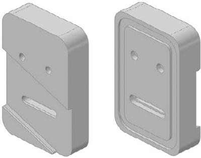
You need to practice some of the skills you will learn on simple parts. Chapter 2 introduced the tools and features you will use, and this chapter teaches you how to string the simple features together intelligently. In this section, I'll show you how to build the simple part shown in Figure 4.1. While the shape is simple, the techniques used and discussed here are applicable to a wide variety of real-world parts. The discussion on how to model the part contains information on some of the topics you need to understand in order to do the work.
The first feature that you create should be positioned relative to the Origin. Whether there is a corner of a rectangle that is coincident to the Origin, the rectangle is centered on the Origin, or dimensions are used to stand the rectangle off from the Origin at some distance, you need to lock the first feature to the Origin with every part you build.
When working with a simple part, the entire part can usually be described as rectangular or cylindrical. In cases like these, it is easy to know where to start: you simply draw a rectangle or a circle, respectively. On complex parts, it may not be obvious where to start, and the overall part cannot be said to have any simple shape. In cases like these, it may be best to select the (or a) prominent feature, mounting location, functional shape, or focus of the mechanism. For example, if you were to design an automobile, what would you designate as the 0,0,0 Origin? The ground might be a reasonable location as would the plane of the centers of the wheels. As long as everyone working on the project agrees, many different reference points could work. With that in mind, it seems logical to start the rectangular part by sketching a rectangle. Select the Top plane and sketch a rectangle centered on the part Origin.
Your next decision is about part symmetry. This part is not completely symmetrical: modeling a quarter of it and mirroring the entire model twice is not going to be the most effective technique. Instead, you should build the complete part around the Origin and mirror individual features as appropriate. To start this type of symmetry, you need to sketch a rectangle centered on the Origin. The centered rectangle is something that you will create frequently.
Figure 4.2 shows a centerpoint rectangle that has been sketched with the centerpoint at the part Origin. This creates symmetry in both directions. You can use additional construction geometry and sketch relations to make the rectangle only symmetrical side to side.
Tip
To make a rectangle work like a square, use an Equal sketch relation on two adjacent sides. This only requires a single dimension to drive the size of the square.
Best Practice
If you are dimensioning a horizontal line, the best way to do it is to simply select the line and place the dimension. Selecting the line endpoints can also work, but selecting the vertical lines on either side of the horizontal lines is not as robust. The problem is that if you use this third method, deleting either of the vertical lines causes the dimension to be deleted. In the first two dimensioning methods, dimensions are not deleted unless you remove one of the endpoints, which requires deleting two lines: the horizontal line and one of the vertical lines.

Extrude feature options
The Extrude feature is one of the staples of SolidWorks modeling. Depending on the type of modeling that you do, the Extrude feature may be one of your main tools.
The Extrude interface
The From panel establishes where the Extrude feature starts. By default, SolidWorks extrudes from the sketch plane. Other available options include:
Surface/Face/Plane. The extrude begins from a surface body, a face of a solid, or a reference plane.

Extruding from a surface
Cross-Reference
Surface features are discussed in detail in Chapter 27.
Vertex. The distance from the sketch plane to the selected vertex is treated as an offset distance.
Offset. You can enter an explicit offset distance, and you can change the direction of the offset.
Direction 1 and Direction 2
Direction 1 and Direction 2 are always opposite one another. Direction 2 becomes inactive if you select Mid Plane for the end condition of Direction 1. The arrows that display in the graphics window show a single arrow for Direction 1 and a double arrow for Direction 2. For the Blind end condition, which is described next, dragging the arrows determines the distance of the extrude.
Following is a brief description of each of the available end conditions for the Extrude feature:
Blind. Blind in this case means an explicit distance. The term is usually used in conjunction with holes of a specific depth, although here it is associated with a boss rather than a hole.
Up to Vertex. In effect, Up to Vertex works just like the Blind end condition, except that the distance is parametrically controlled by a model vertex or sketch point.
Up to Surface. Up to Surface could probably be better named Up to Face, because the end does not necessarily have to be an actual surface feature. This end condition may display a warning if the projection of the sketch onto the selected face extends beyond the boundary of the face. In that case, it is advisable to knit several faces together into a surface body and to use the Up to Body end condition.
Offset from Surface. By default, Offset from Surface extrudes until it reaches a specified distance from a selected surface. There are two methods for determining the type of offset and one to determine direction.
The default offset method behaves as if the selected surface were offset radially, so that a surface with a 4-inch radius and a 1-inch offset would give a curvature on the end of the extrude of a 3-inch radius.
The second method, called Translate Surface, behaves as if the surface were moved by the offset distance.
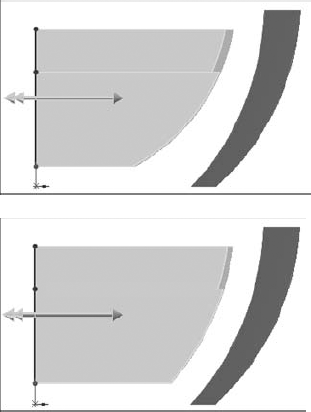
Offset from surface using the default and Translate Surface options
Reverse Offset refers to when the offset stops short of the selected face or when it goes past it.
Up to Body. The Up to Body end condition is very useful in many situations, especially when receiving the error message, "The end face cannot terminate the extrusion," from the Up to Face end condition.
Mid Plane. The Mid Plane end condition eliminates the Direction 2 options and divides the extrude distance equally in both directions; for example, if you specify a 1.00-inch Mid Plane, SolidWorks extrudes .50 inches in one direction and .50 inches in the other direction.

The Reverse Offset option
Through All. The Through All end condition is available only when there is already solid geometry existing in the part. When used for an extruded boss (which adds material), it extrudes to the distance of the farthest point of the solid model in a direction perpendicular to the sketch plane. When used for a cut, it simply cuts through everything.
Up to Next. Up to Next extrudes the feature until it runs into a solid face that completely intercepts the entire sketch profile. If a portion of the sketch hangs over the edge of the face, the extrude feature will keep going until it runs into a condition that matches that description, which may be the outer face of the part in the direction of the extrusion.

The Up to Next end condition used with a Cut extrude


Best Practice
When dealing with molded or cast parts, certain types of features, such as draft, fillets, and shells, are often the targets of users trying to assign best practices. This is partially because using draft, fillets, and shells is very much like playing Rock, Paper, Scissors; the only way to win this game is by luck. Arranging the features in the correct order so that the model is efficient and achieves the desired results is challenging. It is usually best to apply draft as a separate feature rather than using it in the definition of the Extrude feature. It is also best to apply draft after most of the modeling is done, but before you apply the cosmetic fillets and before you use the shell feature.
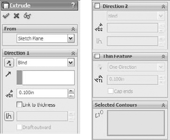
Thin Feature panel
The Thin Feature panel is activated by default when you try to extrude an open loop sketch (a sketch that does not fully enclose an area). The end-condition options remain the same. What changes is the feature applies a thickness to the sketch elements in the manner of a sheet metal part, thin-walled plastic part, or a rib. The Thin Feature panel of the Extrude PropertyManager, along with a representative thin feature extrusion.

The Thin Feature panel and a thin feature extrusion
The Cap Ends option is available only when you specify a Thin Feature to be created from a closed loop sketch. This creates a hollow, solid body in a single step. You can also use Thin Features with cuts, and they are very useful for creating slots or grooves.
Contour selection enables you to select areas completely bounded by sketch entities for use with features such as Extrude. For example, you could use a sketch like the number sign (#). Although it breaks the rule and cannot be used with regular extrusion methods, you can use contour selection to select the box in the center, which is completely bound by sketch elements.
SolidWorks works best when the sketches are neat and clean, when nothing overlaps, and when no extra entities exist. However, when you need to use a sketch that does not meet these criteria, you can use this alternative method.
Best Practice
I believe this feature was introduced into SolidWorks only to keep up with other CAD packages, not because it is a great feature. I do not recommend using contour selection on production models. It is useful for creating quick models, but the selection is too unstable for any data that you may want to rely on in the future. The main problem is that if the sketch changes, the selected area may also change, or SolidWorks may lose track of it entirely.
One of the attractive things about Instant 3D is that it allows you to make changes to parts quickly without any consideration for how the part was made. For example, the cylindrical part was made from a series of extrudes, with a hole cut through it with draft on the cut feature. The flat faces can be moved, and the cylindrical faces offset. Behind the scenes, SolidWorks figures out which sketches or feature parameters of which features have to be edited. This saves you time searching the FeatureManager to figure out which features or sketches control a given face. As you work through more complex parts, you will see how handy this can be at times. You can activate or deactivate Instant 3D using the icon on the Features toolbar.
Note
When combined with the sketch setting Override Dims on Drag, Instant 3D can be a powerful concepting tool, even on fully dimensioned sketches.
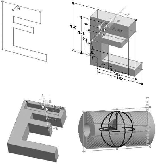
Instant 3D also offers a tool called Live Section. Live Section enables you to section a part with a plane, and you can drag the edges of the section regardless to which features the edges belong. To activate Live Section, right-click a plane that intersects the part and select Live Section Plane.
Instant 3D can also be an effective tool when used in conjunction with the direct editing type of tools such as Move Face. In fact, Instant 3D mimics some of the direct edit type of functionality found in applications such as Sketchup and Spaceclaim.
Chapter 30 discusses the direct edit theme in more detail, and revisits the Instant 3D manipulators in that light.
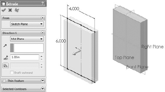
Going back to the sketch in Figure 4.2, I will show you how to continue building the part using the newly learned tools. By centering the sketch on the Origin and extruding by using a Mid Plane end condition, the initial block is built symmetrically about all three standard planes, with the part Origin at the center. In many parts, this is a desirable situation. It enables you to create mirrored features using the standard planes, and helps you to assemble parts together in an assembly later, when parts must be centered and do not have a hard face-to-face connection with other parts. Figure 4.4 shows the initial feature with the standard planes.
Note
When you create a feature from a sketch, SolidWorks hides and absorbs (consumes) the sketch under the feature in the FeatureManager, so you need to click the plus sign next to the feature to see the sketch in the tree. You can right-click the sketch in the FeatureManager to show it in the graphics window.
The next modeling step is to create a groove on the back of the part. How is this feature going to be made? You can use several techniques to create this geometry. List as many techniques as you can think of, whether or not you know how to use them. Later, I will go through several techniques that work.
Tip
One of the secrets to success with SolidWorks, or indeed any tool-based process, is to know several ways to accomplish any given task. By working through this process, you gain problem-solving skills as well as the ability to improvise when the textbook method fails.
Figure 4.5 shows multiple methods for creating the groove. From the left to the right, the methods are a thin feature cut, a swept cut, and a nested loop sketch.

With a thin feature cut, you sketch the centerline, and in the Cut-Extrude feature, select the Thin Feature option and assign a width and depth. The option on the right is what is called a "nested loop," because it has a loop around the outside of the slot and another around the inside. Only the material between the loops is cut away. The method in the center is a sweep where the cross section of the slot is swept around a path to make the cut.
Another potential option could include a large pocket being cut out, with a boss adding material back in the middle. Each option is appropriate for a specific situation. The thin feature cut is probably the fastest to create, but also the least commonly used technique for a feature of this type. Most users tend to use the nested loop option (one loop inside another).
You can control the size of the groove as an offset from the edges of the existing part or you can drive them independently. Again, this depends on the type of changes you anticipate. If the groove will always depend on the size of the part, the decision is easy. If the groove changes independently from the part, you will need to re-create relations within the sketch to reflect different design intent. To create a groove, you can create a rectangle by offsetting the block shape and use sketch fillets to round the corners.
You need to consider one more thing before you create the sketch. What should you use to create the offset — the actual block edges or the original sketch? The answer to this is a Best Practice issue.
Best Practice
When creating relations that need to adapt to the biggest range of changes to the model, it is best to go as far back in the model history as you can to pick up those relations. In most cases, this means creating relations to sketches or reference geometry rather than to edges of the model. Model edges can be fickle, especially with the use of fillets, chamfers, and drafts. The technique of relating features to driving layout sketches helps you create models that do not fail through the widest range of changes.
To create the offset for your part, follow these steps:
Open a sketch on the face of the part. To create the offset, expand the Extrude feature by clicking the plus icon next to it in the FeatureManager so that you can see the sketch. Regardless of how it displays here, this sketch appears before the extrude in the part history. Right-click the sketch and select Show.
Tip
You can view individual sketches and reference geometry entities such as planes from the RMB menu. The global settings for the visibility of these items are found in the View menu. You can access these items faster by using the View toolbar, or by linking the commands to hotkeys.
Right-click the sketch in the graphics window and click Select Chain. This selects any non-construction, end-to-end sketch entities. Click Offset Entities on the Sketch toolbar. Offset to the inside by .400 inches. Apply .500-inch sketch fillets to each of the corners.
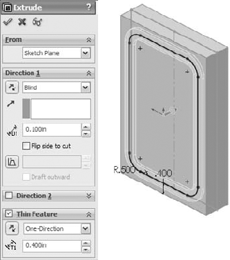
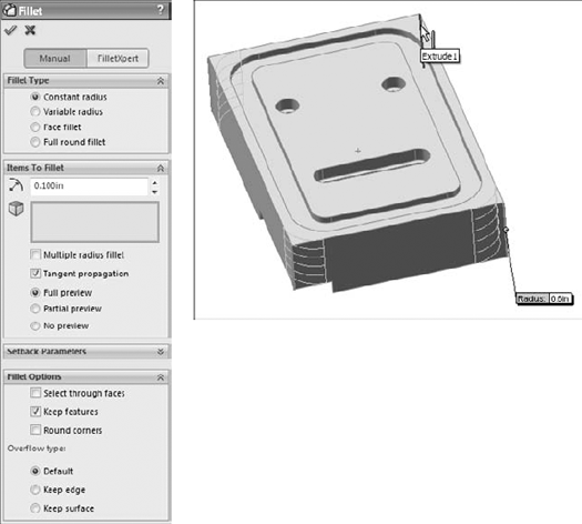
Click Extruded Cut on the Feature toolbar. By default, the extruded cut will cut away everything inside the closed profile of the sketch. Look down the FeatureManager window and select the check box on the top bar of the Thin Feature panel. Make the cut Blind, .100 inch. The Thin Feature type should be set to Mid Plane with a width of .400 inches. The PropertyManager and graphics window should look like Figure 4.6.
Although you could create the next two features more easily and efficiently using a cut, I will show you how to create them as two extrudes. The intent here is to show some useful sketch techniques rather than optimum efficiency. Begin with the part from the previous section and follow these steps:
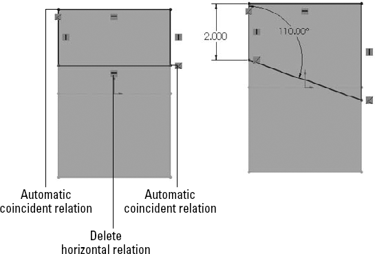
Open a new sketch on the large face opposite from the groove. Draw a corner rectangle picking up the automatic coincident relation to one corner and then dragging across the part and picking up another coincident to the edge on the opposite side. Figure 4.7 shows the rectangle before and after this edit.
Tip
If you want to continue using the recommended best practice mentioned earlier of making relations to sketches rather than model edges, here are a few tips. In some situations (such as the current one), the sketch plane is offset from the sketch that you want to make relations to, and the best bet is to use the Normal To view. The next obstacle is making sure that automatic relations pick up the sketch rather than the edge, and so you can use the Selection Filter to select sketch entities only.
Delete the Horizontal relation on the line that is not lined up with an edge. This enables you to drag it to an angle or apply the dimensions shown in Figure 4.7.
Extrude sketch to a depth of 0.25 inch.
You can delete the Horizontal relation by selecting the icon on the screen and pressing Delete on the keyboard. As a reminder, you can show and hide the sketch relation icons from the View menu. You can check to ensure that the relations were created to the sketch rather than the model edges by clicking the Display/Delete Relations button on the Sketch toolbar, clicking the relation icon to check, and expanding the Entities panel in the PropertyManager. The Entities box shows where the relation is attached to, as shown in Figure 4.8. In this case, it is a point in Sketch1. Without custom programming, there is no way to identify items in a sketch by name, but you already know which point it is; you just needed to know whether it was in the sketch or on the model. The second sketch trick involves the use of a setting.
Choose Tools

Open another new sketch on the same face that was used by the last extrusion. Draw an angled line across the left and bottom sides of the box with the dimensions shown in Figure 4.9. In this case, for this technique to work, the endpoints of the line have to be coincident with the model edges rather than the sketch entities.
This line by itself constitutes an open sketch profile, meaning that it does not enclose an area and has unshared endpoints. Ordinarily, this results in a Thin Feature, as described earlier, but when the endpoints are coincident with model edges that form a closed loop and the setting mentioned previously is turned on, SolidWorks automatically gives you the option of using the model edges to close the sketch. This saves several steps compared to selecting, converting, and trimming manually.
Click the Extrude tool on the Features toolbar. Answer yes to the prompt, and double-click the face of the previous extrusion. SolidWorks automatically uses the face that you double-clicked for an Up to Surface end condition. This is a simple way of linking the depths of the two extrusions automatically. Again, this entire operation could have been handled more quickly and efficiently with a cut, but these steps demonstrate an alternative method, which in some situations may be useful.


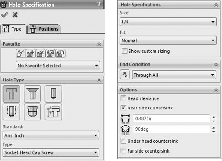
The next features that you will apply are a pair of counterbored holes. SolidWorks has a special tool that you can use to create common hole types, called the Hole Wizard. The Hole Wizard helps you to create standard hole types using standard or custom sizes. You can place holes on any face of a 3D model or constrain them to a single 2D plane or face. A single feature created by the Hole Wizard may create a single or multiple holes, and a feature that is not constrained to a single plane can create individual holes originating from multiple faces, non-parallel, and even non-planar faces (holes may go in different directions). All holes in a single feature that you create by using the Hole Wizard must be the same type and size. If you want multiple sizes or types, you must create multiple Hole Wizard features.
To apply counterbored holes to your part, follow these steps:

Next, click to select the Positions tab at the top of the PropertyManager. This is where you place the centerpoints of the holes using sketch points. It is often useful to create construction geometry to help line up and place the sketch points. Make sure the plane or face that the holes originate from is selected in the Positions tab.
Draw two construction lines, horizontally across the part, with Coincident relations to each side. Select both lines and give them an Equal relation. The point of this step is to evenly space holes across the part without dimensions or equations.
Tip
Although several methods exist to make multiple selections, a box or window selection technique may be useful in this situation. If the box is dragged from left to right, only the items completely within the box are selected. If the box is dragged from right to left, any item that is at least partially in the box is selected.
Tip
SolidWorks displays an error if you try to place a sketch point where there is an existing sketch entity endpoint. If you build construction geometry in a sketch and want to place a sketch point at the end of a sketch entity, you have to create the sketch point to the side where it does not pick up other incompatible automatic sketch relations, and then drag it onto the endpoint.
Place sketch points at the midpoint of each of the construction lines. If there is another sketch point other than the two that you want to make into actual holes, delete the extra points. Dimension one of the lines down from the top of the part, as shown in Figure 4.11. All the sketch relation icons display for reference. Click OK to accept the feature once you are happy with all the settings, locations, relations, and dimensions.

The Hole Wizard does not specifically enable you to cut slots. However, SolidWorks has Slot sketch entities or you can use one of the following methods to cut a slot:

Explicitly drawing the slot. Draw a line, press A to switch to the Tangent Arc tool, draw the tangent arc, and press A to switch back to the Line tool, and so on. Although you can press the A key to toggle between the line and arc functions, you can also toggle between a line and a tangent arc by returning the cursor to the line/arc first point.
Rectangle and arcs. Draw a rectangle, place a tangent arc on both ends, and then turn the ends of the rectangle into construction entities.
Thin feature cut. As you did earlier with the groove, you can also create a Thin Feature slot, although you need to follow additional steps to create rounded ends on it.
Offset in Sketch. By drawing a line, and using the Offset with Bi-directional, Make Base Construction, and Cap Ends settings, it is easy to create a slot from any shape by drawing only the centerline of the slot.
Library feature. A library feature can be stored and can contain either simple sketches or more complex sets of combined features. The library feature is a good option for the counterbored slot used in this example. Library features are discussed in depth in Chapter 19.
Hole Wizard: Using 2D versus 3D sketches
Hole Wizard holes use either a 2D or a 3D sketch for the placement of the hole centers. You can define the centers by simply placing and dimensioning sketch points. Starting with SolidWorks 2010, the 2D sketch type is used by default, with the 3D sketch type only being used when you specify it in the Positions tab of the Hole Wizard tool.
Cross-Reference
In Chapters 17 and Chapter 31, 3D sketches are discussed. Chapter 17 also gives a more detailed description of the Hole Wizard. Chapter 22 has additional information on the display of threads.
The following image shows a part with various types of holes created by the Hole Wizard, including counterbored, countersunk, drilled, tapped, and pipe-tapped holes. The part is shown in section view for clarity; however, the drilled hole is not shown in the figure.
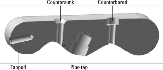
Holes created by the Hole Wizard
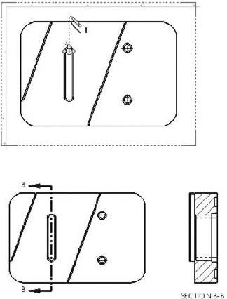
To cut slots in your part, follow these steps:
In this case, use the Centerpoint Straight Slot option. Slots are easiest to create with the Click-click method rather than Click+drag. Click near where you want the center of the slot. Click again for the center of one end; then click a third time for the width/end radius. The Slot PropertyManager is shown in Figure 4.12.
Create a horizontal sketch relation between the origin and the center point of the slot. Add dimensions as shown in Figure 4.12.
Note
Using the Add dimensions option in the Slot PropertyManager can help you size the slot more quickly. This does not require the Enable on screen numeric input option to be turned on.
From this sketch, create an extruded cut that extrudes up to the surface of the counterbore in the holes. The through hole for the counterbored slot is also a slot, and so you can use the same technique.
Open a sketch on the bottom of the previous slot, and draw a straight slot. Make the new slot 0.05 inch smaller than the first slot. You can create a cut using the Through All end condition.

Tip
Picking up relations automatically may seem difficult at first, but with some practice, it becomes second nature. When trying to find the center of an arc, the centerpoint is usually displayed and is easy to select. However, when making a relation to an edge, the centerpoint does not display by default. To display it, hold the cursor over the arc edge for a few seconds; a marker that resembles a plus sign inside a circle will show you where the center is, thus enabling you to select it with a sketch tool and pick up the automatic relations.
In Figure 4.13, the first centerpoint has already been referenced, and the cursor is trying to find the centerpoint of the other end of the slot.
As mentioned earlier, it is considered a best practice to avoid using sketch fillets when possible, using feature fillets instead. Another best practice guideline is to put fillets at the bottom of the design tree, or at least after all the functional features. You should not dimension sketches to model edges created by fillets unless there are no better methods available. Several chapters could be written just about fillet types, techniques, and strategies in SolidWorks. Chapter 7 deals with more complex fillet types.
Do not dimension sketches to model edges that are created by fillets. While the previous best practice about relations to sketch entities instead of model edges was a mild warning, you must heed this one more carefully.

To add fillets and chamfers to your part, follow these steps:
Initiate a Fillet feature, and select the four short edges on the part. Set the radius value to .600 inches. Click OK to accept the Fillet feature.
Tip
When selecting edges around a four-sided part, the first three edges are usually visible and the fourth edge is not. You can select invisible edges by expanding the Fillet Options panel of the Fillet PropertyManager, and selecting the Select through faces option. When you have a complex part with many hidden edges, this setting can be bothersome, but in simple cases like this, it is useful. Figure 4.14 shows this option in action.
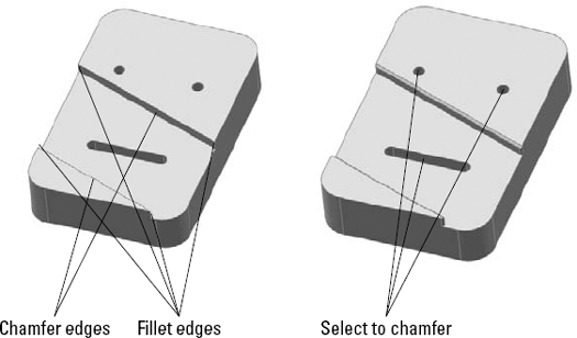
Apply chamfers to the edges of the angled slot through the part, as indicated in Figure 4.15. Make the chamfers .050 inches by 45 degrees.
Chamfers observe many of the same best practices as fillets.
Tip
Feature order is important with features like chamfers and fillets because of how they both tend to propagate around tangent edges. Although you can turn this setting off for both types of feature, it is best to get the correct geometry by applying the features in order.
The Fillet Xpert, which helps you to manage large numbers of overlapping fillets by automatically sorting through feature order issues, is discussed in detail in Chapter 27.
Select the four edges that are indicated for fillets in Figure 4.15. Apply .050-inch-radius fillets.
Apply a last set of .050-inch chamfers to the backside of the counterbores and slot.
The finished part is simple, but you have learned many useful techniques along the way. In the rest of this chapter, you will put the part together with other parts to form an assembly and then create a quick 2D drawing of the part and the assembly to document the design.
Up to this point, you have been learning about how to create geometry, or parts. Assemblies involve organizing that geometrical data to represent real products or parts of products. Assemblies can be complex or simple. They can be structured in a single level or use many subassemblies. Assemblies can be static or allow Dynamic Assembly Motion. Relationships in the assembly can also drive part geometry.
This part of this chapter serves as an introduction to some of the basic functions and main features of assemblies. Because all the geometry creation is done in the part document, most of what goes on in the assembly document has to do with organizing that geometry in space.
Cross-Reference
Chapters 12 to 16 discuss various aspects of assemblies in detail.
The following pages describe common techniques that are used in assemblies. The part created earlier in this chapter is assembled with some additional parts that have already been created. The main point here is to give you a basic understanding of the assembly functions that exist, and how they work before exploring various aspects of the software in detail in Part II.
This tutorial uses parts called Chapter4Frame.sldprt and Chapter4Screw.sldprt from the CD-ROM, in the material for Chapter 4.
To create a simple assembly, follow these steps:
From the CD-ROM, open the part named
Chapter4Frame.sldprt. With the part open, click the Make Assembly From Part/Assembly button on flyout toolbar under the New button in the title bar. (If you have not made a custom template for assemblies, use the default assembly template that installed with SolidWorks.) Move the cursor to the assembly Origin, where the cursor changes to indicate that the part Origin will be lined up with the assembly Origin. If the Origin is not visible on the screen, choose the ViewThe first part that you insert into an assembly has a Fixed constraint applied to it. This constraint is indicated by the (f) in front of the name of the part in the FeatureManager. Figure 4.16 shows the placement preview and cursor from Step 1, as well as the FeatureManager after the part has been added.
Cross-Reference
The Frame part is a weldment. Weldments are discussed in detail in Chapters 31 and 26. Weldments are multi-body parts.
Open the part that you created in the previous tutorial. If you do not have it, then you can open a prebuilt copy from the CD-ROM materials for Chapter 4, named
Chapter4SimpleMachinedPart.sldprt. Once you open the part, change to the assembly window.

Tip
You can press Ctrl+Tab to change between open documents, and Alt+Tab to change between open applications. These Windows conventions are not exclusive to SolidWorks.
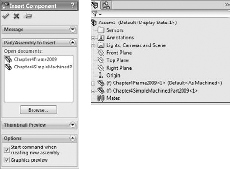
From the assembly menus, choose Insert
ComponentExisting Part/Assembly. This displays the PropertyManager, as shown in Figure 4.17. Select the machined part from the selection box and click in an open space in the graphics window to place it.Newly placed parts in the assembly (except for the very first part) are completely undefined in terms of position or location. Instead of the (f) symbol, for Fixed, the newly placed part displays a (– symbol, which means Underdefined. You can change a Fixed part to underdefined by selecting Float in the RMB menu. Figure 4.17 also shows the FeatureManager with the new part in it. It is a little confusing that (f) stands for Fixed when the opposite condition, Float, also starts with an f.
Note
Parts in an assembly are positioned relative to one another with mates. Mates are in many ways similar to sketch relations.

Tip
You can move a part in an assembly by clicking the part and dragging it with the LMB (left mouse button). It follows whatever mates you have applied to it. To rotate a part that does not have any mates applied to it, drag the part with the RMB. The MMB (middle mouse button) still rotates the view.
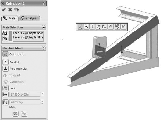
Select the Coincident mate, and then the faces as shown in the figure. If the machined part is turned as it appears in Figure 4.18 (so that it interferes with the welded frame if the selected surfaces touch), then click the Flip Mate Alignment button on the pop-up toolbar, or toggle the Mate Alignment buttons in the PropertyManager. Close the popup toolbar by clicking the green check mark icon.
Best Practice
In contrast to sketch relations, most assembly mates have alignment orientation. Flat faces can be coincident in one of two orientations separated by 180 degrees. The same is true of concentric relations, as well as others. SolidWorks orients a part to the closest orientation that works. This means that it is often best to preposition parts to make it easier for the software. This usually involves some combination of rotating the view and rotating the part.
Select the top angled face of the angled frame member and the corresponding flat face of the machined part. Figure 4.19 shows which faces to select. Make these faces coincident. In this case, the parts are already in the correct orientation, and so there is no need to pre-position them. Click the green check mark icon to accept the mate.
One more mate is required to fully define the position of the machined part. Drag the part and verify that it slides up and down the angled weldment member. Find the two tapped holes in the weldment and slide the machined part so that the holes appear in the counterbored slot. Ideally, the holes should be symmetrical with the part, but the slot was created to allow room for adjustment.
Expand the machined part in the FeatureManager and select its Front plane. From the View menu, turn on the display of temporary axes and Ctrl+select the temporary axes in the centers of the threaded holes in the frame, as shown in Figure 4.20. Select the Symmetric mate on the Advanced Mates panel. Turn off the display of temporary axes when the mate is complete.
Through the menus or Assembly toolbar, click Insert Component and use the Browse button to find the existing
Chapter4Screw.sldprtpart on the CD-ROM, or on your hard drive if you have copied it there.Notice that this part behaves differently in certain situations. For example, when the cursor is over empty space, it is attached to the centroid of the part, but when the cursor is over a flat or cylindrical face, the part snaps to that face. This is because the part uses a Mate Reference, enabling planar and cylindrical faces to get Coincident and/or Concentric mates automatically when the part is dropped on them.
Make sure that the Push Pin feature is activated in the Insert Component PropertyManager and then drop the part at the bottom of each counterbored hole. The part automatically gets Concentric and Coincident mates. Figure 4.21 illustrates the location where you should drop the part. Click OK to accept the part placement.
You need to place two more screws in the assembly, but these cannot be automatically mated; you need to do this manually. Copy two instances of the screws. To copy a screw, Ctrl+drag the part either from the graphics window or from the FeatureManager and drop it into the graphics window.
Position the part and the view so that you can see the cylindrical body of the screw and the cylindrical face of the threaded hole in the C-channel. With the Mate function active, select both faces and click OK. Repeat the process for the other screw and hole.
Now click the underside of the screw head and the counterbored surface of the slot, making sure they will be coincident, and click OK. Repeat the process for the other screw.
Save and close the assembly.


This is a quick overview of the basic assemblies' functionality, which is expanded on in later chapters.
If you are coming to SolidWorks from a dedicated 2D software, you will be creating drawings very differently from what you may be used to. In 2D software, you draw each view individually, and when a change occurs, you have to go back through the views and ensure that each view is updated appropriately. In 2D, views are sometimes created sparingly because they are difficult to create and to update. This includes view types such as Isometric views, complex sections, and views projected at non-orthogonal angles.
In SolidWorks, drawing views are almost free, because they are simply projected from the 3D model. Updates are made in the 3D model, and all views update automatically from there. You can handle dimensions in a couple of ways, either using the dimensions that you used to create the model, or placing new dimensions on the drawing (best practice for modeling is not necessarily the same as best practice for manufacturing drawings). To make a simple drawing, follow these steps:
Click the New button from the Standard toolbar or choose File
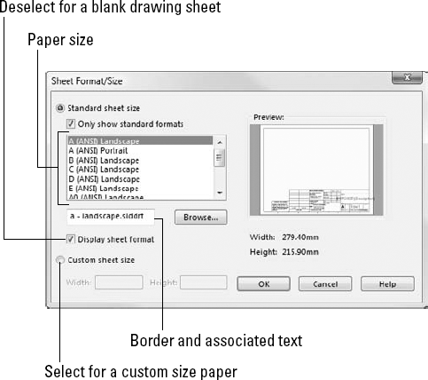
New. From the New SolidWorks Document window, select the Drawing template. The template contains all the document-specific settings.After selecting the drawing template, the Sheet Format/Size dialog box appears, as shown in Figure 4.22. Select the D-Landscape sheet size, as well as the format that automatically associates with that sheet size, and click OK. If the Model View PropertyManager appears, click the red X icon to exit.
Before creating any views on the drawing, set up some fields in the format to be filled out automatically when you bring the part into the drawing. Right-click anywhere on the drawing sheet (on the paper), and select Edit Sheet Format.
Zoom in to the lower-right corner of the drawing. Notice that there are several variables with the format $PRPSHEET:{Description}. These annotations are linked to custom properties. Some of them have properties with values (such as the Scale note), and some of the properties do not have values (such as the Description).

Warning
If you are using a SolidWorks default template and a circle appears around your note, and then use the Text Format PropertyManager that appears when you are creating a note, expand the Border panel, and change the Circle option to None.

To return to Edit Sheet mode (out of Edit Format mode), select Edit Sheet from the RMB menu. A little text reminder message appears in the lower-right corner on the status bar to indicate whether you are editing the Sheet or the Format.
From the Drawings toolbar, click the Standard 3 View button, or through the menus, choose Insert
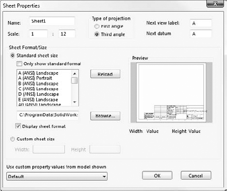
Drawing ViewStandard 3 View. If the Chapter4SimpleMachinedPart document does not appear in the list box in the PropertyManager, then use the Browse button to select it. When you click the OK button, the three drawing views are created.Drawing views can be sized individually or for each sheet. The Sheet Properties dialog box in Figure 4.23 shows the sheet scale. If this is changed, all the views on the sheet that use the sheet scale are updated. If you select a view and activate the Drawing View PropertyManager, you can use the Scale panel to toggle from Use Sheet Scale to Use Custom Scale.
Warning
In the United States, drawings are traditionally made and understood using the Third Angle Projection, which is the ANSI (American National Standards Institute) standard. In Europe, drawings typically use First Angle Projection, which is the ISO (International Organization for Standardization) standard. If you are not careful about making and reading your drawings, you could make a serious mistake. There are times when in the United States, the SolidWorks software will install with ISO standard templates, which will project views using First Angle Projection. When you're using a template that you are unfamiliar with, it is a good idea to check the projection method. To do this, right-click the drawing sheet and select Sheet Properties. The Type of projection setting appears in the top middle of the dialog box, as shown in Figure 4.23. This dialog box looks similar to the Sheet Format/Size dialog box, but it has some additional options, including the projection type.

You can change the appearance of the drawing view in several ways.
View
DisplayTangent Edges with Font uses phantom line type for any edge between tangent faces.View
DisplayTangent Edges Removed completely removes any tangent edges. This is not recommended, especially for parts with many filleted edges, because it generally displays just the outline of the part.Shaded or Wireframe modes can be used on drawings, accessed from the View toolbar.
Perspective views must be saved in the model as a named view and placed in the drawing using the view name.
RealView drawing views are not available on a drawing except by capturing a screen shot from the model and placing this screen shot in a drawing. The same applies to PhotoWorks renderings.
Look at the custom properties that you created in the title block. The date is there because you entered a specific value for it, but the Name field is not filled in. This is because there is no User property in the part. Right-click the part in one of the views and select Open Part. In the part window, choose File
Cross-Reference
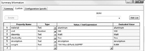
When used in models and formats, Custom Properties are an extremely powerful combination, especially when you want to fill in data automatically in the format, in a BOM (Bill of Materials), or a PDM (Product Data Management) product. These topics are discussed in more detail in Chapters 20 and 24.
When you flip back to the drawing (using Ctrl+Tab), the Name column now contains the value of your initials.

Bring the cursor down to the circular edge of the slot to activate the center point of the arc. Once the center point is active, you can use the dotted inference lines to ensure that you are lined up with the center. Another option is to create manually sketch relations. Turning on temporary axes displays center marks in the centers of arcs and circles. Figure 4.25 shows the technique with the inference lines being used. Draw the section line through the slot and then place the section view.
As mentioned earlier, you can use two fundamentally different methods for dimensioning drawings:
Model Items imports the dimensions used to build the SolidWorks model and uses them on the drawing. These dimensions are bi-directionally associative, meaning that changing them on the drawing updates the model, and changing them on the model updates them in the drawing. On the surface of things, this sounds too good to be true, and it is. The potential problems are that you might not model things the way you would dimension them for the shop. You have to answer several questions for yourself, such as do the leader lines go to the right locations or can they be moved and the dimensions usually come in in such a way that they require quite a bit of moving them around.
Reference (driven) Dimensions can be applied to the drawing view directly. These are only associative in one direction, meaning that they measure what is there, but they do not drive the size or position of the geometry. All changes must be made from the model. Again, on the face of things, this appears to be redundant and a waste of time, but in my personal estimation, by the time you finish rearranging dimensions, checking to ensure that you have everything you need and hiding the extraneous dimensions, you are usually far better off using reference dimensions.
Best Practice
Users have strong opinions on both sides of this issue. The best thing for you to do is to use both methods and decide for yourself.
If you choose to use the Model Items approach, you can do this by choosing Insert
Model Items. Then specify whether the dimensions should come from the entire model or just a selected feature. You also need to ask whether the dimensions should come into all views or just the selected one, and whether you want just a certain type of dimension, annotation, or reference geometry.Once the dimensions are brought in, you need to move some of them from one view to another, which you can do by Shift+dragging the dimension from the old location to the new location. Ctrl+dragging predictably copies the dimension. You can move views by dragging an edge in the view.
This chapter helps to lay the foundation for the more detailed information that will follow. The chapters in Part I include recommendations and answers to questions that help you to develop an intuition for how SolidWorks software operates, which is the most crucial kind of knowledge when troubleshooting a modeling or editing problem.
This chapter has glossed over many of the important details in order to give you a quick overview of the basic functionality in SolidWorks for the three main data types: Parts, Assemblies, and Drawings. Later chapters expand on this information significantly.