
Chapter 4 provides a brief introduction to the basics of assemblies, how to put parts together, the basics of mating, and so on. The basic process for putting assemblies together remains the same for assemblies of any size, but once the assembly passes a certain point — and this point is likely different for each user or application — the assembly will benefit from some sort of organization or management techniques. This chapter introduces you to the tools and techniques that are available to help you manage performance issues as well as general-use issues, efficiency, browse-worthiness, or searchability.
From Chapter 4, you know that an assembly can contain parts and mates. Real-world assemblies can become much more complex. As the number of parts and design requirements for an assembly grows, you may need to add some of the following types of assembly elements. (You may already be familiar with some of these from having worked with part documents.) The assembly elements are listed here, and described in detail either later in this chapter or in other chapters.
Assembly equations
Assembly Layout feature
Assembly layout technique
Assembly reference geometry (plane, axis, point, coordinate system)
Subassemblies
Folders for parts
Folders for mates
Mates
Assembly features (cuts that are made once the parts are assembled)
Component patterns
Mirror components
In-context reference placeholders
Smart Fasteners
Smart Components
Virtual components
Envelopes
Assembly configurations
Assembly Design Table
Assembly Bill of Materials (BOMs)
Hidden/Suppressed/Lightweight/SpeedPak
Sensors
Hole Series
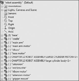
These elements are shown in Figure 12.1.
The three standard planes and the Origin in the assembly FeatureManager design tree are all familiar to you, as are the other standard items, such as the Annotations, Design Binder, Sensors, and Lights and Cameras folders. These items offer the same standard functionality of their part document counterparts.
Note
Remember that you can use choose Tools
Assembly equations work mainly like part equations, but with some additional complications and considerations. For example, one of the additional features of assembly equations is the ability to drive the dimensions of one part from another part. The syntax is slightly different for this application, as shown in Figure 12.2. Overall, issues with equation order and using driven dimensions on the right side of the equation are the same between parts and assemblies.

Cross-Reference
Equations are discussed in detail in Chapter 9.
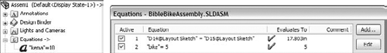
Notice the "->" symbol after the Equations folder in the Assembly FeatureManager. This means that there is an external or in-context reference. An external reference means that an aspect of the part is dependent upon something outside of the part. This has file management implications because you must maintain the names of the files so that they always recognize the other file involved in the external relation. In-context means that one part has a relation to another part in positions determined by an assembly. So in this case, the in-context external reference can only be solved if the original part, the referenced part, and the assembly where the relationship was created are all open at the same time.
Cross-Reference
In-context references are discussed in depth in Chapter 16.
When one part drives another part in this way, the assembly must also be open to drive the relationship. If just the two parts are open individually, then changing the driving part does not update the driven part; because the relationship was created in the context of the assembly, the assembly must also be open to facilitate the change.
Link values and global variables also work in assemblies, but they do not work between parts. Local assembly sketches can use these functions, and the parts can use them when edited in the context of the assembly, but they cannot cross any document barriers (links must remain within a single document).
Equations update with new part names regardless of how the part is renamed. Names of subassemblies also update when assembly files are renamed. This includes renaming a document using the Save As command, using SolidWorks Explorer, or using Windows Explorer. It also includes redirecting the assembly to the new part name, as well as renaming the assembly using each of these techniques. If the assembly can find the part and recognizes the part as the one that it is looking for, then the equation will work.
Some of the methods named previously for renaming parts are not recommended; for testing purposes I specifically tried to break the relationships in the equations by using them. SolidWorks Explorer and the Save As methods can be effective when used properly. References between files are a different issue altogether from an equation's references to local file names.
While assembly equations are certainly a valid way to control part sizes, I would recommend using assembly or part configurations, possibly with design tables, to accomplish something similar. Equations and configurations do not mix well because the two methods compete to control the dimensions. I recommend configurations with design tables over equations.
Assembly configurations are discussed in Chapter 14. Design tables are discussed in Chapter 10.
Warning
You may have unexpected results if a single dimension is controlled from more than one location. For example, if you have a part-level equation and an assembly-level equation, then one of the equations will be automatically set to Read Only and will not be used.
Cross-Reference
The Layout feature is described in more detail in Chapter 16, while the technique using assembly sketches to lay out an assembly is described here. The material in this chapter is written as if the Layout feature does not exist, mainly to give you a straightforward view of how the technique works without worrying about two different functions at the same time.
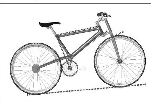
The layout sketch is a very useful tool for laying out a mechanism in an assembly or even details on parts within the assembly. Sketches in the assembly have the same characteristics as they do in the part environment. In Figure 12.3, the assembly layout sketch is indicated with a heavy dashed line for emphasis.
When combined with in-context techniques, assembly layout sketches can help to determine the shape of parts, or the location, size, or shape of features within the parts. You can also use layout sketches to mate assembly components to far more robust and dependable mates, rather than mating part to part. The sketch shown in Figure 12.3 is used for both of these techniques. The shape of the frame and the major pivot points are established in the 2D sketch. The wheels are also mated to the sketch.
When you use an assembly layout sketch for either the in-context part building or simply part positioning, the main advantage that it offers is giving you a single driving sketch that enables you to change the size, shape, and position of the parts. You can use as many layout sketches as you want, and you can make them on different sketch planes. This enables you to control parts in all directions.
Warning
When using layout sketches, it is assumed that the relationships are created such that the sketch drives everything else. However, there is nothing preventing you from using other things in the assembly to drive the sketch. You should avoid this type of conflict, called a circular reference. It can create sketches that change with every rebuild and can seriously impact rebuild times. When using any type of in-context relations, you need to be careful to establish one or more driving entities, which are not in turn driven by other entities.
To take this a step further, it is best to avoid daisy chaining, where A drives B, B drives C, and so on. It is better practice to make A drive both B and C directly. This saves on rebuild times and troubleshooting. See the sidebar on using the skeleton or wide tree approach in Chapter 11 for more details on the benefits of this type of modeling and an example part.
One of the drawbacks of this technique is that you give up dynamic assembly motion. To move the parts, you have to move the sketch and rebuild. The part does not move until the sketch is updated. If you need to combine layout functionality with dynamic assembly motion, see the Layout feature in Chapter 16.
Virtual components are covered in more depth in Chapter 16. Virtual components are parts that are saved so they are internal to the assembly. You can save them out so that they are external to the assembly and can be reused in other assemblies. You can also convert external components to virtual components. Virtual components, as the name suggests, can be either parts or subassemblies.
Using virtual components is a technique that is useful for concept work in assemblies, but you will not see them show up on any best practice list. The main limitation of this technique shows up in the form of data management and reuse. I recommend limiting your use of virtual components because the technique promotes what many users and administrators consider to be sloppy practice.
Planes and axes are frequently created within assemblies to drive symmetry or placement of parts. You can use assembly layout sketches to create the reference geometry entities. When you create reference geometry within the assembly in this way, be aware that the normal history-based parent/child relationships are still followed. The familiar icons for reference geometry entities are also used in the assembly tree.
Because features such as sketches and reference geometry are history based and found in the assembly tree, at least a portion of the assembly FeatureManager is history based. However, not all of it is. For example, the list of parts and subassemblies is not history based.
Sketches and reference geometry may appear before or after the list of parts, subassemblies, and mates. All the remaining entity types that can be found in the assembly FeatureManager are also history-based features, and you can reorder them in the tree. However, several situations can disrupt the process. Under normal circumstances, sketches and reference geometry at the top of the assembly FeatureManager are solved, then the parts are rebuilt if required, and then the mates. This ensures that the sketches and reference geometry are in the correct locations so that if parts are mated to them, all the components end up being the correct size and in the right position.
Assembly-level reference geometry can be created that references component geometry instead of layout sketches. This creates a dependency that changes the usual order. For example, the planes are usually solved before the part locations, but when the plane is dependent on the part location, the plane has to be solved after the part. If a part is then mated to the plane, you are beginning to create a dependency loop, such that the plane is solved, followed by the part, then the plane again because the part has moved; and then the mate that goes to the plane has to resolve the part.
Best Practice
If you are a bit confused by all of this, don't worry. You can simply follow this rule: Do not mate to anything that comes after the mates in the assembly FeatureManager tree. This includes assembly planes or sketches that are dependent on part geometry, assembly features such as cuts, in-context features, component pattern instances, Series Holes, or Smart Fasteners.
This is probably a lot of information if you are a new user, but if you remember this rule, you can avoid creating models with circular references, where A is dependent on B, which is dependent on A — a never-ending loop that causes major problems for large assembly rebuild times.
Parts and subassemblies are shown with their familiar icons in the design tree. You can reorder and group them in folders, which is covered in the next section.
In manufacturing, once parts are assembled, secondary machining operations are sometimes applied to them to ensure that holes line up properly, or for other purposes. For example, assembly features can be cut extrudes, cut revolves, or hole features. These features appear only in the assembly, not in the individual parts.
You should not confuse assembly features with in-context features. In-context features are created when you are editing a part in the assembly with a reference between parts, but the sketch and feature definition are in the part itself.
Because the options for locally defined patterns are comparatively limited, users generally like to use part feature patterns to drive the component patterns when possible.
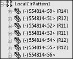
Component patterns are listed at the bottom of the assembly FeatureManager with a set of components under a LocalPattern icon. The component instances under the LocalPattern can be controlled in several ways, including assigned configurations, colors, and display states. The pattern can even be dissolved, leaving the components, but dissolving the intelligent pattern that places them.
Performance
To improve performance, it is best to pattern subassemblies if possible. If it is not possible, then patterning a group of parts is the next best option. Making multiple patterns, one for each part, is an inefficient way to accomplish the same thing.
When you create the relation, a placeholder has to remain in the assembly to hold this information. This placeholder is called an Update Holder. The Update Holders do not display by default. To see them, you must right-click the top level in the FeatureManager and select Show Update Holders. They only exist when in-context references exist in the assembly, and there is one Update Holder for each in-context sketch or feature. You cannot do very much with the Update Holders, other than query them for parent/child relations and to list the external relations, but they serve as a reminder that you have in-context references to maintain. For more information on this feature, see Chapter 16.
Popular perceptions of in-context techniques aside, in-context modeling is a powerful extension of parametric design techniques. If you follow the best practice suggestions outlined in Chapter 16, you will soon gain confidence and master this technique rather than being frightened by it. The functionality works, and if you do not abuse it, it will serve you well.
Smart Fasteners, Toolbox, and the Hole Wizard are discussed in detail in Chapter 17. This is the only functionality beyond what is found in SolidWorks Standard edition that I deal with in this book.
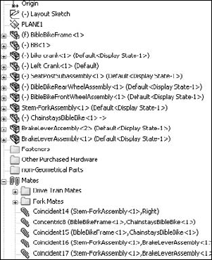
The Hole Series is a Hole Wizard–type feature that you apply in an assembly. This wizard leaves the feature icon in the assembly, but also adds features directly to the individual parts. It also adds in-context Update Holders to the assembly FeatureManager, as shown in Figure 12.4. The Series Hole is designed to go through a series of parts, placing the appropriate hole type in each part, counterbore, through, threaded, and so on.

Figure 12.5 shows first the SpeedPak PropertyManager, which you access by right-clicking an active configuration, and selecting Add SpeedPak. Each configuration can have only one SpeedPak.
Figure 12.5 also shows the configuration list with the SpeedPak listed indented under the Default config, and the entire assembly. The final image shows the SpeedPak inserted into an assembly document, consisting of a single face and two solid bodies. Notice the special icon associated with SpeedPaks. You can change a part in an assembly from or to a SpeedPak in the same way that you would change a configuration using Component Properties.
Remember this is a tool for increasing assembly speed, and to increase speed, there is always something that you have to give up. SpeedPak can be thought of in some ways like Lightweight assemblies and components in that it is display-only data. If your expectations of the tool are in line with the actual functionality, you will be very satisfied with the functionality SpeedPaks offer. For this reason it is important to understand the abilities and limitations of SpeedPak.
You can use any faces or bodies that you select in the Include lists either manually or through the Quick Include sliders (which automatically select bodies and faces based on size) in assemblies to mate to or in drawings to dimension to. Any geometry that is not selected is included as a ghost — it displays, but cannot be selected. When the cursor gets near ghost geometry, the ghost fades away, revealing only selectable geometry. Notice at the bottom of the SpeedPak PropertyManager that you can also choose to remove the ghost data and further increase the memory savings.
The SpeedPak is self-contained. All the selected face and body geometry is saved inside the assembly. If you want to send someone a visual representation of an assembly, make a SpeedPak configuration and send only the assembly file — no parts are required. This is the equivalent of being able to put an eDrawing file into an assembly.
You can even use SpeedPaks with drawings. Just remember that only edges created by the faces or bodies in the Include lists can be dimensioned to. Some functionality exists for the ghost data, such as BOM inclusion and numbered balloons. Ghost data displays as gray on the drawing, while geometry in the Include list is black.

Model of Garmin assembly from the SolidWorks demo sets
The primary tool for organizing assemblies is the subassembly. A subassembly is just a regular assembly that is used as a component in another assembly.
Best Practice
The number of levels of subassemblies is not limited to a specific number, although for different sizes and types of assemblies, I encourage you to establish a best practice for your company. For example, establish a guideline that suggests that subassemblies of 100 parts or less go no deeper than three levels.
You can use several criteria to determine how subassemblies are assigned:
Performance
BOM
Relative motion
Pre-fabricated, off-the-shelf considerations
According to assembly steps for a process drawing
To simplify patterning
The underlying question here is based on the multiple functions of your SolidWorks assembly model. Is the assembly intended primarily for design? For visualization? For documentation? For process documentation? When used primarily for design, the assembly is used to determine fits, tolerances, mechanisms, and many other things. As a visualization tool, it simply has to look good and possibly move properly if that is part of the design. As a documentation tool, it is important how the model relates to the BOM, and the order in which subassemblies are added. As a process tool, you need to be able to show the assembly in various intermediate states of being assembled, likely with configurations.
I have seen companies create multiple assembly models for different purposes. Sometimes the requirements between the different methods are contradictory and cannot all be met at the same time with a single set of data. Again, depending on what information you need to be able to extract from your SolidWorks models, you may want to approach assembly modeling and organization differently, and you may need to create multiple assembly models to accomplish everything.
You can create subassemblies from parts that already exist in an assembly. To do this, select the parts that you want to add to the subassembly using Shift+, Ctrl+, or box select techniques, and then select Form New Subassembly Here from the right mouse button (RMB) menu. You are then prompted to assign a name or possibly select a template for the new subassembly.
Warning
When creating a new subassembly from existing parts or when moving parts into or out of a subassembly from the upper-level assembly, some things may be lost. For example, mates are moved from the upper level to the subassembly. If you have in-context relationships, they may be removed. Operations that create subassemblies cannot be undone easily.
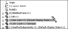
Once you have created the subassembly, you can add or remove components using the drag-and-drop method. For example, Figure 12.6 shows the cursor that indicates that the part named Left Crank is being moved into the subassembly named bike crank. To move a part out of a subassembly, simply drag the part into the upper-level assembly.
Note
When you are dragging a part out of an assembly and into another one, you may again see the cursor symbol that appears in Figure 12.6. If you do not want this to happen, hold down the Alt key while dragging. The cursor symbol changes to the Reorder cursor (a reversed, L-shaped arrow), and the part is placed after the subassembly rather than within it.
Along with the RMB menu option Form New Subassembly Here, which takes existing parts and puts them into a newly created subassembly, you can use another option called Insert New Subassembly. The names of these functions do not adequately describe the difference in what they do. Insert New Subassembly inserts a blank subassembly at the point in the design tree that you indicate by right-clicking it. You can place components into the subassembly by dragging and dropping them from the main assembly, or you can open the assembly in its own window and insert parts by using the usual methods.
If you would like to get rid of a subassembly but want to keep its parts, then you can use the Dissolve Subassembly option through the RMB menu. This option has some of the same consequences of the Form New Subassembly Here option in that mates are moved from the subassembly to the upper-level assembly, and you may lose in-context relations and assembly features.
Performance in SolidWorks is a word used to mean speed. Subassemblies can contribute to speed-saving modeling techniques by segmenting the work that the software needs to do at any one time.
The mates that contribute to putting the pieces of an assembly together are solved at the level of the top assembly. Under normal circumstances, subassemblies are treated as static selections of parts that are welded together, and their mates are not solved at the same time that the top-level assemblies' mates are solved. This segmenting of the mates leads to improved performance by only solving one set of mates at a time.
Mates are usually solved as a single group unless there is a special situation, such as mates to in-context features, component pattern instances, or an assembly feature, all of which have already been described in this chapter. When one of these situations occurs, the mates have to be divided into separate groups or solved multiple times. This is done transparently behind the scenes so that the user does not have to worry about it. Multiple rebuilds affect the user only in terms of rebuild times.
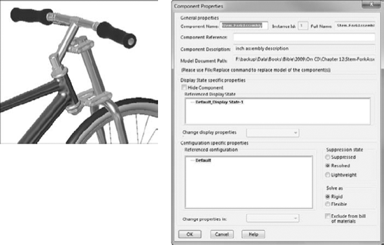
To access the Component Properties dialog box, right-click the subassembly and select Component Properties from the menu.
Flexible subassemblies have become more reliable and easier to use over the last several releases. I encourage you to work with them or do some experimentation to see if they assist your modeling process. If you find they cause trouble in some situations, they are easy enough to simply deactivate.
If you have assemblies that were built in older versions of SolidWorks (such as SolidWorks 2001+), mates used to be split up into multiple mate groups, which represented the groupings that mates were solved in. This was forced by mating to the history-based features in the assembly FeatureManager. SolidWorks no longer displays mate groups, but the groups are still used in the background to solve mates. This is another change that SolidWorks has made to the software that simplifies the user's interaction with the software, but also makes it obvious that things are now happening behind the scenes that you can't control.
The Bill of Materials, or BOM, is a table that is placed either into a drawing of an assembly or in an assembly itself. This table shows the parts used in the assembly and includes other information, such as part numbers, quantities, descriptions, and custom property data.
Cross-Reference
SolidWorks BOM functionality is discussed in depth in Chapter 24.
Businesses often represent assemblies and subassemblies in various ways by using MRP (Manufacturing Resource Planning) or ERP (Enterprise Resource Planning) software. The methods that accountants and manufacturers use to organize assemblies are not always the same as those that engineers or designers might choose, but some companies require the BOM on the drawing to match the MRP or ERP Bill of Materials.
Best Practice
When you are forced into modeling something in an unnatural way to satisfy an outside requirement such as special BOM requirements, it might be best to detach the unnatural part and model normally. In the situation mentioned here — where MRP is forcing how the assembly is put together by requiring the BOM to match MRP — I recommend separating the BOM from the assembly structure rather than building an assembly that makes other SolidWorks' functions difficult. This ensures that the BOM becomes a manually maintained document.. Alternatives to this approach would be to make configurations or entirely new assembly documents to drive the BOM.
A more natural way to group subassemblies is by considering relative motion. In the bicycle example, each wheel is a separate subassembly because it moves as a unit relative to the rest of the assembly. Figure 12.8 illustrates where relative motion might be on the bicycle.

Grouping subassemblies by relative motion is great for assembly modeling, but it does not usually reflect product reality very well. Using this method, you often end up with parts in the subassembly that will have to be disassembled in order to actually put the physical parts together. However, if your only consideration is ease of modeling, then this is probably the method to use.
If you are modeling a product that is created from a shopping list of purchased components, then it may make the most sense to organize your subassemblies into groups of parts that are purchased together. In fact, purchased subassemblies are often modeled as single parts, except when relative motion is required in the purchased assembly.
For example, in the bicycle assembly, the sprockets on the rear wheel are purchased as a separate unit, and yet the part that mounts onto the wheel moves relative to the sprockets that are driven by the chain. This is an example of a purchased part that would be modeled as a subassembly to show relative motion. The bicycle chain, another purchased subassembly, has not yet been added to this assembly, and is a more complex model. The desire to show all of the individual links moving through the path may override both the complexity of assembling it and the performance considerations of exercising all of the mates.
Although the BOM method of organizing assemblies sometimes leads to unnatural solutions, you should not discard it altogether. If you can devise concessions in order to make the BOM work automatically, then you should do this.
Manufacturing and assembly processes need to be documented as well as individual part design. You often need to create exploded-view assembly instructions for manufacturing or service documentation at each step of a multi-step assembly process. Figure 12.9 shows a page of this type of process documentation.

This is certainly a task that is different from the initial design or modeling of the assembly, and it may require an entirely separate assembly model. Generally, you can perform the different steps by using a separate configuration for each process step, with exploded views for each configuration.
Balloons number the parts according to the item number that is used in the BOM, but, of course, you do not know the item numbers until the BOM is created. You can influence the item numbers by reordering the parts in the assembly (which I discuss later in this chapter), by manually editing item numbers, or by manually numbering the balloons. I cover all of this in detail in Chapter 24.
Each step corresponds to an assembly configuration (discussed in Chapter 14), and you can place them on a separate sheet of the drawing (discussed in Chapter 21). Each configuration can have multiple exploded views, if necessary, to show all the steps.
The most efficient way to pattern large numbers of components in an assembly is to pattern a single subassembly with all the components to be patterned in it. While this may not be easily combined with some of the other considerations that I mentioned previously, it is another option that you can use to organize assemblies.
Folders are primarily used in the assembly FeatureManager for grouping parts and mates into either special classifications for easy browsing, or groups that can be easily hidden and shown, or suppressed and unsuppressed, as appropriate. Figure 12.10 shows some examples of these folders.
You can add folders to the assembly FeatureManager in one of two ways:
Add existing components to a new folder
Create an empty new folder
To use the Add To New Folder tool, right-click a component or mate (or selection of components or mates) and select Add To New Folder from the menu. This moves the component or mate into the folder. Folders do not affect the assembly in any functional way; they are simply for organization, to speed browsing and selection.
To move an item into an existing folder, just drag the item (component or mate) onto the folder. If the folder is expanded, showing its contents, then you can also drag the item as if you were reordering a feature in the FeatureManager of a part, and drop it in the list of items where you would like it.
If you are dragging a part or assembly and trying to put it immediately after an assembly, a cursor like the one shown in the center in Figure 12.11, may appear. This cursor means that the part is going to become part of the assembly. If this is not what you are trying to do, then hold down the Alt key while dragging; the part is placed into the folder immediately after the assembly, instead of being made a part of the assembly. The third image in Figure 12.11 shows the cursor with the Alt key pressed.
There are times when you may want to reorder items in the assembly tree. For example, you may want to place items close to one another in the tree, or you may be preparing to put items that are next to one another into a single folder. You may want to reorganize components for the BOM display.
You can reorder mates simply by dragging them. Mates display in the order in which they are created, but the order is not significant. They can be reordered however you like.
Components also display in the order in which they are added to the assembly, and you can reorder them in any way you like.

Best Practice
It is often useful to have an ordering strategy that helps you work with the model. I usually try to keep the biggest parts, the parts that everything else is mated to, or the part that is treated as "ground," as the first part(s) in the assembly. I put the fasteners and other cosmetic or BOM-driving parts at the end of the tree, usually in a descriptive folder.
Display options for items in the FeatureManager are often overlooked, but can be useful for displaying data about parts, subassemblies, mates, and features. Figure 12.12 shows the RMB options. You must right-click the top-level assembly name in the FeatureManager to access this menu.
Note
All these options are available for parts and drawings as well, except for the View Features option and the View Mates and Dependencies option, which are related to assemblies.

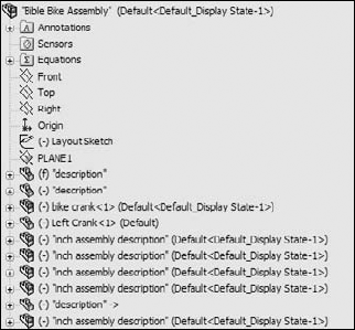
If you are so thorough that you have added descriptions to your features, then you are doing well. This option refers to the descriptions of features in the parts. The middle image in Figure 12.12 shows a section of the FeatureManager for the bicycle frame part; some of the features have had descriptions added with both of the options for feature names and feature descriptions turned on. The image to the right in Figure 12.12 shows the result of turning off the feature name, with only the feature description option turned on. If no feature description has been created, then the feature name displays. Feature descriptions always appear in double quotes.
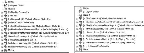
The image on the left in Figure 12.13 shows the default arrangement of displaying component and configuration names in the assembly FeatureManager. This example uses the rear wheel assembly from the bicycle assembly. In assemblies, you cannot turn off the component names and the component descriptions. SolidWorks issues this statement when you try to turn off both the name and the description: "You cannot hide both the component name and the file name. At least one must be visible in the tree."
The message in the previous paragraph distinguishes between the filename and the component name that is listed for individual parts or subassemblies in the assembly FeatureManager. You can specify the component name in the Component Properties dialog box by right-clicking the component in the assembly FeatureManager and selecting Component Properties.

However, you can assign a component name for a component that is different from the filename only if a special setting is turned off. (The setting defaults to on.) You can access this setting by choosing Tools
After going through the preceding steps, you still receive the warning message about the filename and the component name. This is apparently an "unintended feature," or bug, and should likely say that you cannot turn off both the component name and the component description at the same time.
There may be a situation where you want to show a name other than the filename in the FeatureManager. For example, your company may be using sequential part numbers for the filenames that are difficult to read, and you want something descriptive in the design tree so that you do not need a cross-reference sheet next to your computer that equates filenames to meaningful descriptions.
If you prefer, you can avoid a lot of problems by just using the part description instead of the filename or the component name. The choice is up to you.
One of the problems with using the component description is shown in Figure 12.14, where the user did not enter proper descriptions for the parts, and SolidWorks used the default description in the templates. The tire and spokes use configurations, which display in the figure.
SolidWorks 2010 adds Component Reference capabilities. In the Component Properties dialog, shown earlier in Figure 12.7, the second row at the top enables you to enter Component Reference information. This is typically used in electrical diagrams for similar components with different values, such as power ratings, capacitance or resistance. Instances of the same component in a SolidWorks assembly that have the same Component Reference can be listed together on a BOM. Instances with different Component References are listed separately on the BOM.
Figure 12.15 shows parts listed in a pattern that have Component References listed for each instance.
In order for Component References to be used in balloons on an assembly drawing, the drawing must have a BOM with a Component Reference column. BOMs are handled in detail in Chapter 24, where this topic of Component References will be revisited.
The last set of options shown in Figure 12.12, determines if you see the part features or the assembly mates after the name of each component in the assembly tree. The default setting is for the part's features or the subassembly's components to display, just as if the part or subassembly were open in its own window.
The View Mates and Dependencies option can also show the features, but they are placed into a separate folder. This option makes it very easy to see the mates that are assigned to an individual component. For example, in Figure 12.16, the image to the right shows the mates directly under the BibleBikeFrame part. This often makes troubleshooting much easier because it isolates the mates for a single part. Notice also that the first folder under the part name in the image to the left in Figure 12.16 is the Mates folder. This indicates that, regardless of whether you choose to display mates or features, you always have easy access to the other type.

The View Mates tool is extremely valuable for looking at how an assembly is held together with mates. When you right click on a component in the assembly and choose View Mates from the RMB menu, SolidWorks highlights the component you clicked on, and makes all parts that mate to that component transparent. Any parts that are not related are hidden. SolidWorks also opens up a small dialog box with the list of mates touching the component you clicked on.
Figure 12.17 shows this arrangement using the Bible Bike assembly. If you are a SolidWorks veteran, this works very differently from the way View Mates worked in the past, but I hope you will agree with me that this is a big help in mate visualization.
If you Ctrl-select multiple components before starting the View Mates tool, SolidWorks no longer puts the common mates in bold, it just lists them at the top of the dialog box.

SolidWorks is incredibly complex software, and there are many tools to do many small tasks. This is true nowhere more than it is in assemblies. Users have such wide expectations of the software in various areas, and everyone needs something different. Many tools exist to help you put together, maintain, and evaluate efficient assemblies. The tools in this section are important tools that don't fit into the other categories.
To create a sensor in an assembly, right-click the Sensors folder in the assembly FeatureManager. If the Sensors folder is not there, choose Tools

I was not able to confirm that AssemblyXpert would find a circular reference, but SolidWorks and I might be using different definitions of circular reference. My definition is a list of parts referencing other parts where the references form a loop, with one part as the start and end point. AssemblyXpert could not find this kind of reference loop. SolidWorks may be using a more explicit definition where specific geometry within a part is both driving and driven.
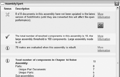
Figure 12.19 shows the AssemblyXpert results. Notice that the results include the information formerly included with the Assembly Statistics: part and subassembly count, along with mates, unique parts, and so on.
The information in the AssemblyXpert is certainly useful, particularly for newish users who may not know to look for things like this already. You can use it as both a diagnostic and a learning tool.
In this tutorial, you take an assembly that is already put together and group its components into subassemblies, and then convert one subassembly into a flexible subassembly. Note that some of the commands and RMB options you are asked to select may not be shown on the truncated RMB menus. To remedy this, click the double-arrow at the bottom of the RMB menu or choose Tools
Follow these steps to learn how to effectively arrange items in an assembly:
Start by opening the Chapter 12 Robot
Assembly .sldasmfile from the CD-ROM, Chapter 12 folder.Notice that the names for the files are long and somewhat difficult to read. This would also apply for files that use sequential numbers for the file name instead of a descriptive name.
To display a more readable name, right-click the name of the assembly at the top of the FeatureManager, select Tree Display from the menu, and then turn on Show Component Descriptions. Repeat these steps and this time turn off Show Component Names.
Figure 12.20 shows the display of the FeatureManager after the change. Even the top-level assembly uses its description rather than its file name.
Notice that two components still use their clumsy file names rather than easy-to-read descriptions. This is because descriptions were never entered for those two components.
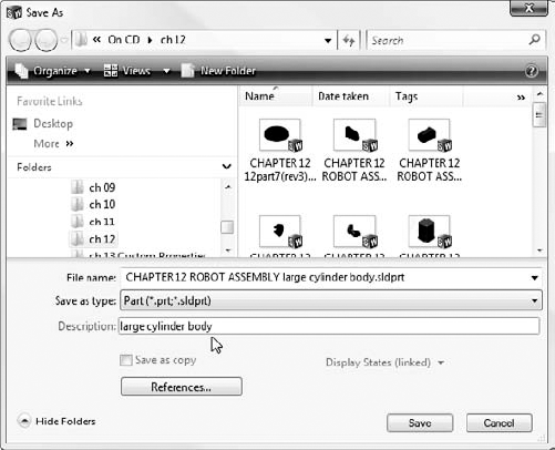
Open the Large Cylinder Piston part by left-clicking the part in the FeatureManager and clicking the Open icon. Choose File

If the display has not yet updated, press Ctrl+Q to force the tree to rebuild.
Open the Large Cylinder Body part. In this part, choose File
Ctrl+ select the large cylinder piston and the large cylinder body parts from the FeatureManager. Then right-click and select Form New Assembly Here from the menu. If your assembly template has a description, it will appear in the FeatureManager. If not, the file name will appear.
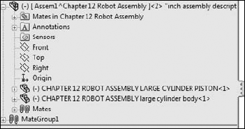
You have just created an assembly as a virtual component while the parts are external documents. If you switch the tree display to show file names briefly, you will see what is shown in Figure 12.22, the name of the assembly is Assem1^Chapter 12 Robot Assembly. So the virtual component gets a default name (Assem1) followed by the name of the parent assembly (Chapter 12 Robot Assembly) to ensure that it has a unique name, if there are other virtual components in other assemblies.
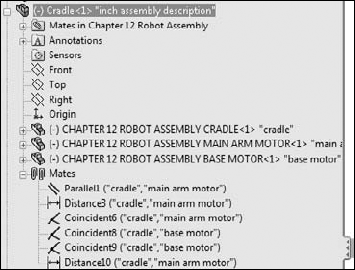
Ctrl+ select the Base Motor, the Main Arm Motor, and the Cradle, and make another new subassembly. After this one is created, right-click the subassembly and select Save Assembly (In External File) from the menu. Change the name of the assembly from Assem2 to Cradle. Save it in the same path as the rest of the parts.
Once a virtual component is saved externally, you cannot use undo to reverse it, but you can right-click the external file in the FeatureManager and select Make Virtual from the menu.
In Figure 12.23, notice that several of the mates came along into the new subassembly. These are the mates between the motors and the cradle. The mates that locate the cradle to the other parts in the assembly have remained in the upper-level assembly.
Note that you cannot undo the subassembly operations. If you need to remove the assembly but keep the parts, right-click the assembly and select Dissolve Subassembly from the menu.
If you try to move the parts in the assembly, you should notice that all parts work as they should except that the Main Arm does not move up and down. This is because you turned the cylinder and piston into a subassembly, and the subassembly mates are not solved in the top level, which means the subassembly cannot move within itself.
To get around this, you need to make the subassembly into a flexible subassembly, which will solve the subassembly's mates in the top-level assembly,
Right-click the cylinder subassembly in the FeatureManager, and select Component Properties from the menu. In the lower-right corner of the dialog box, there is an option to Solve as Rigid or Flexible. Change this setting to Flexible.

This tutorial uses the BibleBikeAssembly.sldasm file found on the CD-ROM for Chapter 12. Open the file and follow these steps to learn about managing the FeatureManager:
Create a new subassembly within the existing assembly using the parts BibleBikeFrame and ChainstayBibleBike. Name this new assembly
FrameAssembly.SLDASM.Reorder the new FrameAssembly to the top of the design tree.
Reorder the other parts and assemblies so that the bigger assemblies appear higher on the list, and the parts appear at the bottom. (Remember that the Alt+drag option prevents a component from being placed into a subassembly.)
Drag the part called BB (for Bottom Bracket) into the Frame Assembly (drag without using the Alt key). The assembly FeatureManager at this point is shown in Figure 12.24.
Select both wheels and then select Add To New Folder from the RMB menu. Name the new folder Wheels, and move it to the bottom of the tree.
Expand the Mates folder, select the first four mates, and put them in a new folder (select Add To New Folder from the RMB menu). Name the new folder Centering Mates.
Assemblies are more than simply parts and subassemblies put together with mate relationships; several other types of features and placeholders can also exist in the assembly FeatureManager. Organizing assembly components is fairly straightforward and can offer benefits for finding parts as well as controlling suppression and display states globally.
The assembly FeatureManager contains several options for the data to display for subassemblies, parts, configurations, and features within. Remember that all the data that you include in your SolidWorks documents can be accessed and reused later on, so it is worth the effort to name it properly. Descriptions can be very important, both at the part level and also for features and configs.