
With surface modeling you build a shape face by face. Faces made by surface features can be knit together to enclose a volume, which can become a solid. With solid modeling, you build all the faces to make the volume at the same time. In fact, solid modeling is really just highly automated surface modeling. Obviously there is more detail to it than that, but this definition will get you started.
You can drive a car without knowing how the engine works, but you cannot get the most power possible out of the car by only pressing harder on the gas pedal; you have to get under the hood and make adjustments. In a way, that is what working with surfaces is really all about — getting under the hood and tinkering with the underlying functionality.
The goal of most surface modeling is to finish with a solid. Some surface features make faces that will become faces of the solid, and some surface features only act as reference geometry. Surface modeling is inherently multi-body modeling because most surface features do not merge bodies automatically.
In the end, you may never really need surfaces. It is possible to perform workarounds using solids to do most of the things that most users need to do. However, many of these workarounds are inefficient, cumbersome, and raise as many difficulties as they solve. Although you may not view some of the typical things you now do as inefficient and cumbersome, once you see the alternatives, you may change your mind. The goal for this chapter is to introduce surfacing functions to those of you who do not typically use surfaces. I am not showing how surfaces are used in the context of creating complex shapes, just how you can use them for various general 3D modeling tasks.
The word surfacing has often been used (and confused) to signify complex shapes. Not all surface work is done to create complex shapes, and many complex shapes can be made directly from solids. Many users think that because they do not make complex shapes, they never need to use surface features. This chapter shows mainly examples that do not require complex shapes, in situations where surfaces make it easier, more efficient, or simply possible to do the necessary tasks.
While some of the uses of surfaces may not be immediately obvious, by the end of this chapter, you should have enough information and applications that you can start experimenting to increase your confidence in surfacing techniques.
When dealing with surfaces, you may hear different terminology than the terminology typically used with solid modeling. This special terminology also often exists for surfaces because of important conceptual differences between how solids and surfaces are handled.
These terms are fairly universal among all surfacing software. The underlying surface and solid construction concepts are generally uniform between the major solid and surface modeling packages. What varies from software to software is how the user interacts with the geometry through the software interface. You may never see some of these terms in the SolidWorks menus, Help files, training books, or elsewhere, but it becomes obvious as you use the software that the concepts are relevant.
Knit is also sometimes used in the same way that the zero-distance offset is used, to copy a set of solid faces to become a new surface body.
You can find one nice option that enables you to quickly see where the boundaries of a surface body lie by choosing Tools
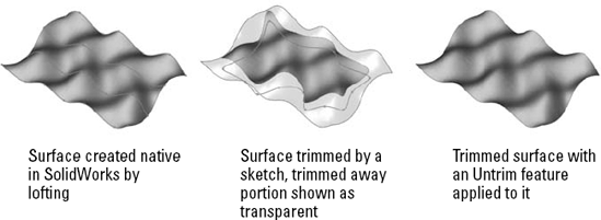
Untrim works on native and imported geometry. It is not truly like feature history in imported geometry, but it does help to uncover the underlying original shape of the face.
Modeling software has long divided itself along Solid/Surface lines with products such as Rhino (strictly surface modeling) and early versions of SolidWorks (strictly solid modeling). However, in the last several years, modelers increasingly enabled both methods and allowed them to interact. This hybrid modeling is a combination of solid and surface modeling. These days, it is much more common to mix methods than it was even five years ago. Surface modeling is slow because you model each face individually, and then manually trim and knit. Cutting a hole in a surface model is much more involved than cutting a hole in a solid. Solid modeling is faster because it is essentially highly automated surface modeling; however, as any software user knows, automation almost always comes at the expense of flexibility, and this situation is no different. Surface modeling puts the compromised power back into your hands.
Solid modeling tends to limit you to a type of parts with square ends or a flat bottom because solids are creating all sides of an object at once. For example, think about an extrusion: regardless of the shape of the sketch, you have two flat ends. Even lofts and sweeps typically end up with one or two flat ends because the section sketches are often planar. Surfaces enable you to create one side at a time. Another way of looking at it is that using surfaces requires you to create one side at a time.
You will find times when, even with prismatic modeling, surfacing functions are extremely useful, if not completely indispensable. I do not propose that you dive into pure surface modeling just to benefit from a few of the advantages, but I do recommend that you consider using surface techniques to help define your solids. This hybrid approach is sensible and opens up a whole new world of capabilities. I have heard people say after taking a SolidWorks surfacing class that they would never look at the software in the same way again.
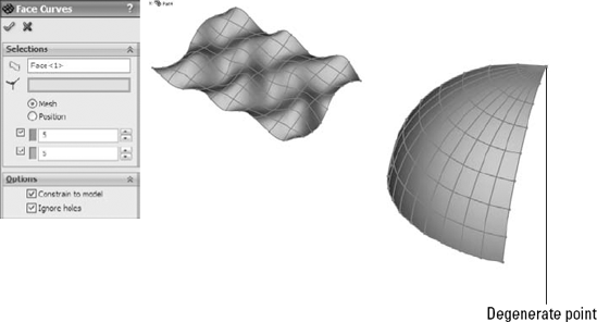
NURBS stands for Non Uniform Rational B Spline. NURBS is the technology that most modern mechanical design modelers use to create 3D geometry. NURBS surfaces are defined by curves in perpendicular directions, referred to as U and V directions, which form a mesh. The fact that perpendicular directions are used means that the surfaces have a tendency to be four-sided. Of course exceptions exist, such as three-sided or even two-sided patches. Geometry of this kind is referred to as degenerate because one or more of the sides has been reduced to zero length. Degenerate geometry is often, but not always, the source of geometrical errors in SolidWorks and other CAD packages.
Figure 27.2 shows some surfaces with the mesh displayed on them. You can create the mesh with the Face Curves sketch tool.
An example of a competitive system to NURBS surface modeling is point mesh data. This comes from systems such as 3DSMax, which create a set of points that are joined together in triangular facets, and can be represented in SolidWorks as an STL (stereolithography) or VRML (virtual reality markup language) file. When displayed in SolidWorks, this data looks very facetted or tessellated into small, flat triangles, but when viewed in software that is meant to work with these kinds of meshes, it looks smooth. Many advantages come with this type of data, especially when it comes to applying colors and motion. However, the main disadvantage is that the geometrical accuracy is not very good. Point mesh data is typically used by 3D graphic artists, animators, and game developers.
By using a SolidWorks add-in such as ScanTo3D (available only in SolidWorks Premium), it is possible to take point mesh data and create a NURBS mesh over it. This is not a push-button solution, but it offers capabilities where none previously existed. ScanTo3D is beyond the scope of this book, but you should find it useful if you are interested enough to read about NURBS and point meshes.
Developable surfaces are surfaces that can be flattened without stretching the material. They are also surfaces that you can extend easily in one or both directions. These include planar, cylindrical, and conical shapes. It is not a coincidence that these are the types of shapes that can be flattened by the Sheet Metal tools.
Developable surfaces are a special type of a broader range of surface called ruled surfaces. SolidWorks has a special tool for the creation of ruled surfaces that is described in detail in the next section. Ruled surfaces are defined as surfaces on which a straight line can be drawn at every point. A corollary to this is that ruled surfaces may have curvature in only one direction. Ruled surfaces are far less limited than developable surfaces, but are not as easily flattened.
Ruled surfaces are used frequently in plastic parts and plastic mold design where draft and parting surfaces from 3D parting lines are needed.
Surface feature equivalents are available for most solid features such as extrude, revolve, sweep, loft, fillet, and so on. Some solid features do not have an equivalent, such as the Hole Wizard, shell, and others. Several surface functions do not have solid equivalents, such as trim, Untrim, Extend, Thicken, Offset, Radiate, Ruled, and Fill.
This is not a comprehensive guide to complex shape modeling, but it should serve as an introduction to each feature type and some of the details about how it operates.
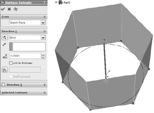
You can also create extruded surfaces from open sketches, and, in fact, that is probably a more common situation than creating a surface with a closed sketch.
When two non-parallel sketch lines are joined end to end, the result of extruding the sketch is a single surface body that is made of two faces with a hard edge between them. If the sketch lines were disjointed, then the extrude would result in disjoint surface bodies. If the sketch lines were again made end to end, but done in separate sketches, then the resulting surface bodies would be separate bodies; the second body would not be automatically knit to the first one as happens with solid features. This is an important quality of surfaces to keep in mind. If you create surfaces in different features and want them knitted into a single body, then you will have to do that manually.
If several edge or sketch segments combine to form one side of a direction, then you must use the SelectionManager to form the edge segments into a group. SelectionManager enables you to select portions of a single sketch or to combine elements such as sketch, edge, and curve into a single selection for use as a profile or guide curve for Boundary or Loft features.
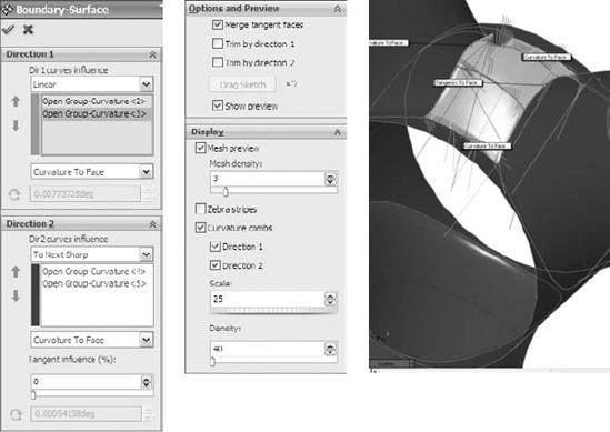
The interface for the Boundary Surface is shown in Figure 27.4.
The types of models where you end up using the Boundary Surface are highly curvy models that are modeled mainly with surface features and require a four-sided patch.
The main advantage of Boundary Surface over Loft is that Boundary Surface can apply a Curvature boundary condition all the way around, while Loft cannot apply curvature on the guide curves. Fill Surfaces also can apply a Curvature boundary condition all the way around.
Boundary Surface can be a rather nuanced feature, but when working on the type of model that suits it well, I default to Boundary Surfaces when possible. Boundary solid features are now also available, and I expect these will also take a little bit of a learning curve to understand where they are best applied.
For a more detailed look at the primary shape creation tools (Sweep, Loft, Boundary, and Fill) and surface modeling in general, please refer to the SolidWorks Surfacing and Complex Shape Modeling Bible (Wiley, 2008).
One of the ways to troubleshoot a failing Offset Surface is to use the Check tool to check for minimum radius. Remember that the area with the minimum radius is only a problem if the curvature is in the same direction as the offset. If a small radius will increase when it is offset, then that small radius is not the problem. The problem comes from the other direction where you are offsetting to the inside of a small radius.
Unlike the Sketch Offset function — and as was shown in Chapter 26 — you can offset surfaces by a zero distance. This is usually done to copy either solid or surface faces to make a new surface body. Zero-distance offset and Knit are sometimes used interchangeably, although Knit causes a problem if you are selecting a surface body that is composed of a single face. Knit assumes that you are trying to knit one body to another, and so, by default, it selects the body, and then fails with the message that you cannot knit a body to itself. Because Knit has this limitation, and Offset does not, I prefer the Offset tool when copying faces to make a new surface body. You may also notice that when you enter a zero for the offset distance, the Offset PropertyManager name changes automatically to Copy Surface.
Knit does have two functions that Sketch Offset does not. One of these is the option to create a solid from the knit body if it forms a closed body. The second option is somewhat more obscure, offering the ability to select all faces on one side of a Radiate Surface. I discuss this option in more depth later in this chapter in the Knit Surface section.
When talking about copying surface bodies, you must also consider the Move/Copy Bodies feature, which is described in Chapter 26. When simply copying a body without also moving it, this feature issues a warning that asks whether you really intend to copy the body without moving it. This is an annoying and pointless message. Also, the Move/Copy Bodies feature does not enable you to copy only a part of a body (selected faces) or to merge multiple bodies into one like the Knit and Offset Surface features.
All things considered, I recommend using the zero-distance Surface Offset feature to copy bodies or parts of bodies unless your goal is to immediately make a solid out of it (in which case you should use the Knit feature) or when using a Radiated surface (typically in a mold-building application).
Tip
The Radiate Surface feature does not give you a preview of the finished surface, only the small arrows that indicate the direction in which the surface will radiate. At times, you may need to switch the arrows to the other side, which you can do by using the arrow button next to the plane selection.
Warning
When creating a Radiate Surface, the use of a loop in the edge selection always results in an incorrect result, because the feature only uses the initial edge that was selected for the loop. As long as individual edges are listed in the selection box, you should be okay.
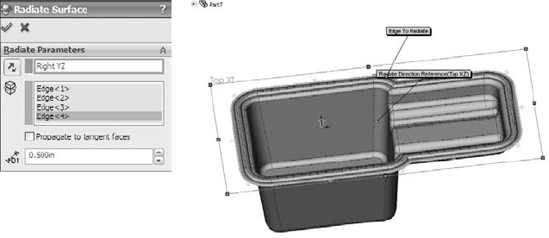
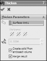
The one application where the Radiate Surface has a very interesting usage is when you combine it with the Knit function, as mentioned earlier. Figure 27.6 shows a part surrounded by a Radiate Surface in which the Knit feature is being used to select all the faces to one side of the radiated surface. The second smaller selection box in the PropertyManager that contains Face<1> is called a seed face and causes the Knit to automatically select all the faces on the same side of the model as the selected seed face. The requirement here is that the Radiate goes completely around the model and separates the faces into faces on one side of the Radiate and faces on the other side of the Radiate. The use of the Radiate with the Seed Face selection is extremely useful for mold creation.

If the knit operation results in a watertight volume, the Try to form solid option turns the volume into a solid. You can also make a solid from a surface using two other functions. The Fill Surface has an option to merge the fill with a solid or to knit it into a surface body; if the knit surface body is closed, then it gives you the option to make it a solid. This is very nice, complete interface design, with options that save you many steps. The Fill Surface feature is described in more detail later in this chapter.
In SolidWorks 2010 the Knit feature has some important new functionality. The Gap Control panel, shown in Figure 27.7 shows the gap between the edges of surfaces to be knit, and enables you to see the gaps in a certain range and force gaps of less than a specified tolerance value, called the Knitting Tolerance, to knit. This replaces the old Minimal Adjustment option in Knit, which was SolidWorks did not go to any great length to help users understand. The Knitting Tolerance tools are easier to understand and more powerful when it comes to forcing knit features to work.

With all powerful tools the possibility of misusing the tool always exists. The ability to play with tolerances is a double-edged sword. On one hand it gives you the ability to force surfaces to knit which may have otherwise not knit at all. On the other hand, if you allow a larger tolerance, SolidWorks may force together surfaces or edges that have problems that should be solved in other ways. such as removal and remodeling. Gap tolerances can cause problems during import operations to other software that doesn't have the capability to adjust tolerances. Certainly use the Gap Control options, but also be aware of the potential problems you might see with data downstream.
However, more commonly, Planar Surfaces are created from a closed sketch such as a rectangle. You can create multiple Planar Surfaces at once, and the surfaces do not need to all be on the same plane or even parallel. This is commonly done to close up holes in a surface model, such as at the bottom of cylindrical bosses on a plastic part, using a planar circular edge. A good example of this is the bike frame part in the material for Chapter 27 on the CD-ROM, named Chapter 27 – bike frame.sldprt.
Remember that a Planar Surface was used in Chapter 26 with the Split feature to split the leg off of an imported part. This was more effective than a sketch or a plane because the split was limited to the bounds of the Planar Surface, not infinite like the sketch or the plane.
The Planar Surface does not knit itself into the rest of the surface bodies around it automatically; you have to use the Knit feature to do this.
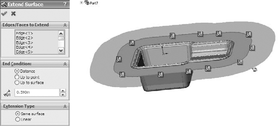
The only item here that requires explanation is the Extension Type panel. The Same surface option means that the extended surface will simply be extrapolated in the selected direction. A Planar Surface is the easiest to extend because it can go on indefinitely without running into problems. A cylindrical surface can only be extended until it runs into itself. Complex lofted or Swept Surfaces are often difficult to extend. Extrapolating a complex surface is not easy to do and often results in self-intersecting faces, which cause the feature to fail.
When the Same surface setting works, it creates a nice result because it does not create an edge where the extension begins; it smoothly extends the existing face.
The Linear option is more reliable than the Same surface option because it starts tangent to the existing surface and keeps going in that direction, working much like a Ruled surface, which is covered later in this chapter. It does not rely on extending the existing surface. This option creates an edge at the starting point of the new geometry.
Sketches
Planes
Other surfaces
When you use surface bodies to trim one another, you must select one of two options: Standard or Mutual Trim. The Standard option causes one surface to act as the Trim tool and the other surface to be trimmed by the Trim tool. When you select the Mutual Trim option, both surfaces act as the Trim tool, and both surfaces are trimmed.
For an example of trimmed surfaces, open the mouse example from Chapter 26 and step through the tree. This shows examples of a couple of types of trimmed surfaces, as well as extended surfaces and others.
Many people overlook the ability to trim a surface with a plane, which can be very handy sometimes. Planes are infinite, which means you have less to worry about when it comes to changes that affect features rebuilding correctly.
Finally, trimming with 2D sketches is well known, but trimming with 3D sketches is less known. There is a 3D sketch tool called Spline on Surface that enables you to draw a spline directly on any surface body. An option exists in the Trim Surface PropertyManager to trim a surface with this type of sketch. This is very useful in many situations if you can remember that it is available.
The Fill Surface is intended to fill in gaps in surface bodies. It can do this either smoothly or by leaving sharp corners. You can use constraint curves to drive the shape of the fill between the existing boundaries. It can even knit a surface body together into a solid, all-in-one step. Beyond this, you can use the Fill Surface directly on solid models and integrate it directly into the solid automatically (much like the Replace Face function, which is described later in this chapter).
Several rather complex examples of the Fill Surface are found in the bike frame example that was originally shown in Chapter 12. One of these fills is shown in Figure 27.10.
The first thing you should notice about the Fill Surface is that it is creating an oversized, four-sided patch and trimming it to fit into the available space. This is one of the reasons why I consider this to be such a magical tool. The four-sided patch I referred to earlier in the section on NURBS is shown very clearly in this feature preview. Also, the trimmed surface concept is illustrated nicely by this feature. Not surprising, if you untrim the Fill Surface, then you return to the surface that is previewed here. In this one function, SolidWorks gives you some useful insight about what is going on behind the scenes.
When using the Fill Surface, it is best to have a patch completely bounded by other surfaces, as shown in Figure 27.9. Fill Surface can work with a boundary that is not enclosed, but it works better with a closed boundary.
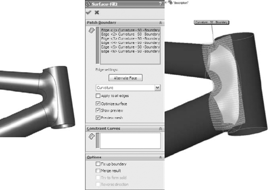
You can set boundary conditions as Contact, Tangent, or Curvature. Contact simply means that the faces touch at an edge. Tangent means that the slopes of the faces on either side of the edge match at all points along the edge. Curvature means curvature continuous (or C2), where the Fill Surface matches not only tangency, but also the curvature of the face on the other side of the boundary edge. This results in a smoother transition than a transition that is simply tangent.
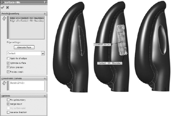
When you select the Optimize Surface option, SolidWorks tries to fit the four-sided patch into the boundary. Notice that on this part, even though the Optimize surface option is selected, it is clearly being ignored because the boundary is a six-sided gap and cannot be patched smoothly with a four-sided patch. It is not necessarily an improvement to make a Fill Surface optimized, even when it works.
Constraint curves can influence the shape of the Fill Surface. An example of this is shown in Figure 27.11. The construction splines shown on the faces of the part were created by the Intersection Curve tool and enabled the spline used for the constraint curve to be made tangent to the surface.

Similar to the Planar Surface, you can also use the MidSurface to create a surface that can be used like a plane. No plane type can create a symmetrical plane, but using a MidSurface, you can create a symmetrical Planar Surface between parallel walls.

If you were to manually perform the functions that are done by Replace Face, then you would start by deleting several faces of the solid, then extending faces, and then trimming surface bodies, and finish by knitting all the trimmed and extended faces back into a single solid body.
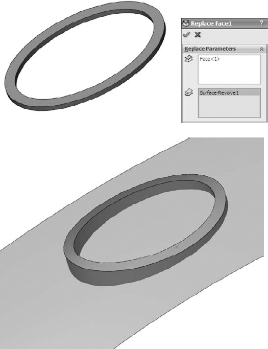
This is a very powerful and useful tool, although it is sometimes difficult to tell which situations it will work in. Figure 27.13 shows a part before and after a Replace Face feature has been added. The surface used to replace the flat face of the solid has been turned transparent. The first selection box is for the original face or faces, and the second selection box is for the surface body with the new faces. The tool tips for each of the boxes are Target Faces For Replacement and Replacement Surface(s), which seem a little ambiguous. I like to think of them as Old (top) and New (bottom).
The Ruled Surface feature in SolidWorks is one of those features that you may never have missed until you see it in action. It is extremely useful for constructing faces with draft, extending faces tangent to a direction, making Radiate Surface types, building molds, and many other applications.
Figure 27.14 shows the PropertyManager interface for the Ruled Surface.
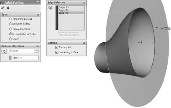
The Ruled Surface works from the edge of a solid or surface body. The feature has five basic types of operations that it can perform:
Tangent to Surface
Normal to Surface
Tapered to Vector
Perpendicular to Vector
Sweep
The Tangent to Surface setting is self-explanatory. The Alternate Face option would be available if the base shape had been a solid, with a face filling the big elliptical hole. This would make the Ruled Surface tangent to the bottom face instead of the side.
With the Normal to Surface setting, it tilts up five degrees from the horizontal because the surface is lofted with a five-degree draft angle at the big end, making a Ruled Surface that is normal. Be careful of using this setting because it looks close to what you may be hoping for, but is slightly off. One of the other options may be a better choice, depending on what you are looking for.
The Tapered to Vector setting needs a plane or axis selection to establish a direction, and then the Ruled Surface is created from that reference at the angle that you set. With a combination of the Alternate Side button and the arrow direction toggle button next to the plane selection, you can adjust the cone created by this setting. The interface to make the changes is not exactly clear unless you use this function often, but it does work.
The Perpendicular to Vector setting is a better option than the Normal to Surface setting when the surface has been created with some sort of built-in draft angle. This is also the setting that looks most like the Radiate Surface feature, although it works much better than Radiate Surface.
The Sweep setting makes a face that is perpendicular to the surface created by Perpendicular to Vector. It is as if a straight line were swept around the edge. This is actually a great way to offset an edge or 3D sketch: using the edge of the surface as the offset of the original.
This section serves as a brief overview of some of the techniques commonly used among people who model using surfaces. This section could be the topic for an entire book on its own. In fact, it is the topic of an entire book that goes into far greater detail. You may want to use the SolidWorks Surfacing and Complex Shape Modeling Bible (Wiley, 2008) to continue your SolidWorks education in far greater detail and depth.
Cross-Reference
Chapter 7 contains more information on end conditions such as Up To Surface and Up To Body.
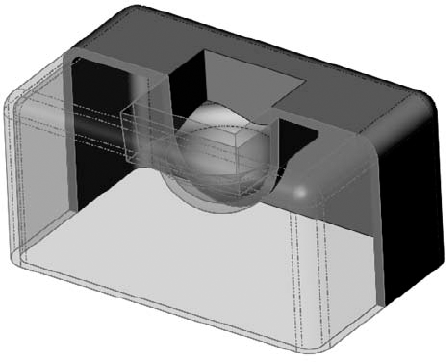
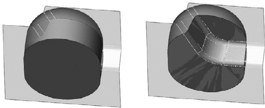
Some modeling situations seem to require elaborate workarounds until you think of doing them with a combination of solid and surface features, such as the part shown in Figure 27.15. This geometry could be made completely with solids, but it would be more difficult. In this case, a surface is revolved, representing the shape at the bottom of the hole, and the cut is extruded up to it. You can follow along with the part from the CD-ROM at Chapter 27 – square hole.sldprt.
Another familiar situation is when you have a feature to place and you want to use an Offset from Surface end condition, but the feature spans two faces. In that situation, you can knit the necessary faces together (or use offset), and then extrude offset from that surface body.
Tip
Using Up To or Offset From Body rather than Face often avoids the common error message, "The end face cannot terminate the extruded feature," especially if the feature that is extruded spans more than one face.
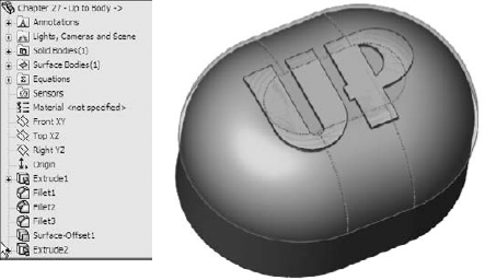
Figure 27.16 shows a part using an Offset Surface to extrude text up to where the text spans more than a single surface. This is a very common application, even if it is not text that is being extruded. The part that was used in Figure 27.15 is on the CD-ROM in the materials for Chapter 26, and is called Chapter 26 – Up To Body.SLDPRT.
When cutting with a surface, the edges of the surface must be outside of the body that is being cut. With sketches, it is advisable to have more sketch than you need so that you are not trying to cut line-on-line. The same applies to cutting with a surface, where it is advisable to have more surface than you need to make the cut.
Figure 27.18 shows that the multiple faces of the letter U on this part have been replaced with a surface from an inserted part. Replace Face is a fantastic tool that you can use in a number of situations, although it is a little particular sometimes and you cannot always predict when it will or will not work.
The Fill Surface is my favorite tool in the SolidWorks software. It can get you out of modeling binds easily, and is often used to cover over nasty modeling mistakes or areas you just can't get right by any other method. In addition to its duty in the complex shapes department, it can also be used as a fast way to create a Planar Surface in some situations. If you do much surface modeling, the Fill feature will become a staple of your diet.

Note
The Fill Surface is an advanced surfacing function. Sometimes, when talking about advanced surfacing functions, or indeed any software function, users have a tendency to sound a little cynical. This is because the tool is often expected to work on very complex geometry. It is not always the software's fault when it cannot perform a particular task, or does not do what you imagine you want it to do. Sometimes, the tool is simply not meant to perform certain tasks, there may be an unseen flaw in the geometry that prevents it from working, or the user does not understand the settings completely. The more complex the work, the more frequently you need to find workarounds to get something done. Avoiding problems does not make them go away. In this book, I have chosen to take a realistic look at most of the features.
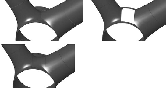
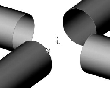
Figure 27.19 shows the Fill Surface blending an intersection between tubes. The image to the left shows the before condition with the tubes coming together at an edge. The center image shows the edge trimmed out using the Trim feature, and the right image shows the hole blended over by the Fill Surface feature.
In Figure 27.20, a solid starts with a Split line on the surface. A sketch is then added, and a Fill Surface is created using the sketch as a constraint and the Split line as the boundary. The Merge Result option in the Fill PropertyManager has a different significance than it does in a solid feature PropertyManager, but the end result is the same. Remember that this is a surface function, and if it does not merge, then it is left as a surface feature.
If you had to go through these steps manually, then you would use the Replace Face feature to integrate the surface into the solid. The key to integrating the Fill Surface directly into the solid without any additional features is the Merge Result option in the Fill PropertyManager.
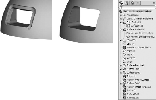
A memory surface is not another new type of feature that you can select from the menu or a toolbar; it is just the name that I gave to a technique that I use from time to time. A memory surface is just a Knit or Offset Surface that is made at one point in the feature tree when a particular face is whole, and reused later when the face has been broken up, but you still need to reference the entire original face. An example of this technique is shown in Figure 27.21. In this case, extra material is created around the opening, and a surface that was created in a Rollback state is used to remove it.
This is another chapter that contains many important ideas, and yet there is only so much space for tutorials. The best way to learn is to experiment. I recommend that you closely follow the tutorial steps once, and then, when you understand the concepts involved, that you can go back and experiment.
Follow these steps to gain some experience with the Cut With Surface feature:
Start by creating a new part and drawing a rectangle on the Top plane, centered on the Origin, about 4 inches by 6 inches, with the 4-inch dimension in the vertical direction.
Extrude the rectangle Mid-plane, by 2 inches.
From the Surface toolbar, select Lofted Surface, and select one 4-inch edge as a loft profile. Then select a second 4-inch edge diagonal from the first one. This is shown in Figure 27.22.
Expand the Start/End Constraints panel, and set both ends to use the Direction Vector setting, selecting the plane that is in the middle of the long direction in each case. In the part shown, the Right plane is used. Click OK to accept the feature. This is shown in Figure 27.22.
From the menus, choose Insert
Cut With Surface. Select the surface from the flyout FeatureManager, and toggle the arrow direction so that the top is cut off. (The arrow points to the side that is cut off.)

Follow these steps to gain some experience with the Offset Surface:
Open the part from the CD-ROM called Chapter 27 –
Offset Tutorial.sldprt.Right-click a curved face of the part and click Select Tangency in the menu.
With the faces still selected, from the Surfaces toolbar, click Offset Surface, and set the surface to offset to the outside of the part by .060 inches. You can tell when the surface is offsetting to the outside when the transparent preview appears. If you do not see the transparent preview, toggle the Flip Offset Direction arrow button. Click OK to accept the feature when you are satisfied.
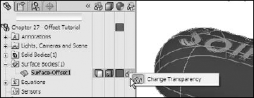
Look in the Surface Bodies folder at the top of the FeatureManager tree, expand the folder, and select the Offset Surface. Then use the Appearances toolbar button to change the transparency of the surface body to about.75. You can also do this through the Display Pane, by clicking in the column following the surface body in the bodies folder that is farthest to the right, as shown in Figure 27.23. This is done so that you can see the part underneath the surface, without mistaking the surface for the actual part.
Tip
It is a common practice to change surface colors to something that contrasts with the part color. I usually use a color like yellow, which suggests temporary status or construction. Some users take this a step further and set the template colors for surface types by choosing Tools
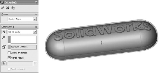
Select Sketch2, and select Extruded Boss/Base from the Features toolbar. Do not mistake the Extruded Surface for an Extruded Solid. Set the end condition to Up To Body, activate the body selection box, and select the Offset Surface body from the Surface Bodies folder. The result is shown in Figure 27.24.
Tip
It is preferable to select the surface from the Surface Bodies folder, rather than the feature list or the graphics window. In this case, you want to extrude up to a body. If you make the selection from the feature list, then you are likely to select a feature (which is okay in this situation, but not in all situations). If you make the selection from the graphics window, then the selection is likely to be interpreted as a face. It is best to be as explicit as possible when making selections because SolidWorks may interpret your selection literally. In this case, it is probably a better idea to use Up To Body for the end condition than Up To Surface, because the goal is really to use the surface body as the end of the feature.
To invert the lettering so that it sits below the surface rather than above the surface, you can make a few simple changes. First, edit the Offset Surface feature and flip the direction of the offset so that the surface is now inside the solid rather than outside the solid. You will not be able to see it unless the solid is either transparent or in wireframe mode.
Next, delete the extrude that you created to extrude the text. There is no way to change an extrude into a cut in this context.
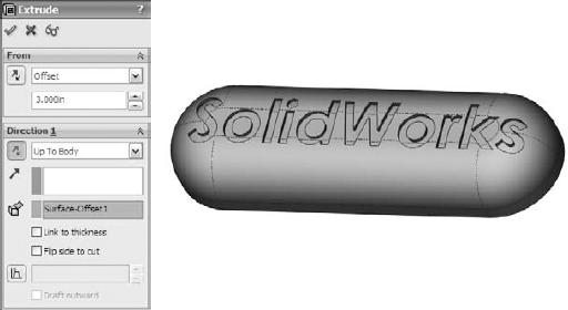
Re-create the extrude as an extruded cut. Use the From settings at the top of the PropertyManager window. The settings and results are shown in Figure 27.25.
Another way to accomplish this would be to use the Move Face tool, select the faces of the letters, and move them .120 of an inch into the solid.
Sometimes fillets do not meet your needs. Blends, such as those shown in the bike frame example, are smoother and can blend just about anything. However, the technique is not exactly straightforward. Follow these steps to gain familiarity with this technique:
Open the part from the CD-ROM for Chapter 27 called Chapter 27 –
Blend.SLDPRT. Box select all the features from the DeleteFace1 to the Shell, and suppress them.On the Top plane, draw a square 2 inches on a side and centered on the Origin.
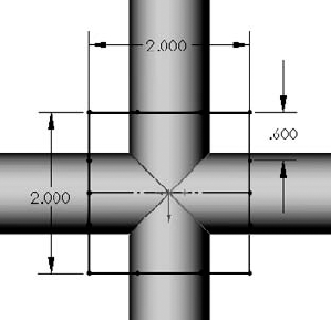
Use the Split Entities tool found on the Sketch toolbar or choose Tools
Sketch ToolsSplit Entities from the menus. Divide each line of the rectangle into three pieces, with the two outer pieces of each line being .6 inches (use an Equal sketch relation). The sketch should be fully defined when you are done. This arrangement is shown in Figure 27.26. This is done because the edges of the tubes need to be broken into sections.Use Delete Face to delete the ends of the four tubes. Set the option to Delete, not the default option of Delete and Patch. This converts the solid into a surface body.
Use the sketch with the split entities to trim out the center section of the tubes, keeping the outer section and leaving four surface bodies. This divides each tube end into four segments where they have been trimmed, as shown in Figure 27.27.
Initiate the Lofted Surface feature, and select the nearest edge segments from adjacent tubes. If the loft preview twists, use the light-blue handles to straighten it out or deselect and reselect one of the edges in approximately the same location as the other edge was selected. Expand the End Conditions panel and set each edge to use the Curvature setting. You may adjust the End Tangent Length option if you want, but keep in mind that this may make the part asymmetrical.
As a note, you may choose to use the Boundary Surface in the place of the loft. For this function, the two are similar enough.
Create Lofted Surfaces all the way around the part, linking all the tubes. Figure 27.28 shows the part with three of the lofts already completed and the last one in progress.
Start a Planar Surface feature, and select the open ends of each tube where the faces were deleted in Step 4.

Note
Not all features allow you to operate from multiple bodies, but the Loft and Planar Surface features do. Features such as Fillet and Draft restrict you to creating features that are associated with one body at a time.
Start a Knit Surface feature, and Shift+select all the bodies in the Surface Bodies folder (select the first body in the list and Shift+select the last body). When you click OK to accept the feature, notice that the number of surface bodies changes to one. Selecting bodies in this way is much faster for large numbers of bodies than selecting them one at a time from the graphics window.
Note
Notice that the open edges of the surface body are shown in a different color. At this point, there are two open edges around the holes at the intersection of the tubes.
This is a situation that the Fill Surface is really meant for. In fact, this technique was created specifically to take advantage of the Fill Surface capabilities. Right-click any of the open edges and choose Select Open Loop. Initiate the Fill Surface. Change the Edge setting option to Tangent, and make sure that the Apply to all edges option is selected.
Select the Merge result option, but leave the Try to form solid option unselected. The model at this point is shown in Figure 27.29, along with the PropertyManager settings that are used.
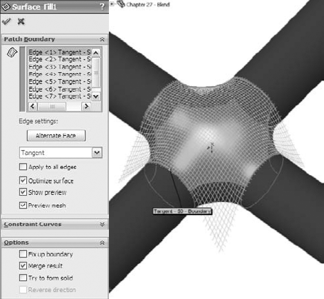
Note
The Optimize surface option is ignored for this part because the opening is eight-sided rather than four-sided. Also note that you may have to change the resolution control slider to get the surface to remain convex instead of going concave in the center.
Click OK to accept the feature.
Start another Fill Surface, turning the part over to use the same selection on the back and the same settings as the first fill. However, on this one, also use the Try to form solid option. Click OK when the selections and settings are complete.
For the last feature, apply a Shell feature, selecting the flat ends of the tubes and shelling to .100 inches. The final state of the model is shown in Figure 27.30.

Surface functions have a wide range of uses other than for complex shape parts, but thinking about your models in terms of surface features requires a slightly different approach. Becoming comfortable with the terminology, and the similarities and differences between solids and surfaces, is the first step toward embracing surfacing tools for everyday work.
You can think of surfaces as being reference geometry — stand-alone faces that you can use to complete various tasks.