In this book, the term master model is used to refer to a technique where an entire assembly is laid out or has its major faces constructed in a single part, and that part is then placed into other files from which the individual parts are created. Master model techniques are usually used in situations that in-context design cannot deal with, or where in-context design is cumbersome.
Master model techniques are a product of four separate features or functions that have some similarities and some differences, and rely heavily on the knowledge of parent/child concepts, multiple bodies, and surface functions. The four features are Split, Save Bodies, Insert Part, and Insert Into New Part. In turn, these four features can be categorized into Push and Pull type functions.
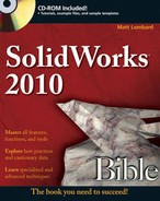
As an example of a master model technique, consider the mouse model shown in Figure 28.1, which should be familiar by now. The overall shape is modeled as a single part, and is split into several bodies using multibody methods. Then, using these master model techniques, the individual bodies are used to create individual part files where detail features are added.
SolidWorks has four distinct features or functions that do essentially the same thing with subtle but important differences. The functionality of the four tools overlaps significantly, but none is an exact copy of another.
Understanding the concepts of parent and child documents is key to understanding the concepts behind master model techniques. A parent document is always the driving document — the one that existed first — so changes to the parent propagate down to the child. The child document is always dependent upon the parent. In these master model schemes, it is not always possible to find the child document from the parent, but you can always find the parent from the child.
The concepts of Push and Pull type functions are ones that I developed and you may not find them in other documentation. I found classifying the techniques helpful in understanding which tool was best for various situations. Push simply means that data from the parent document is pushed out to the child and the relationship is defined in the parent document. Pull means that the child document pulls data from the parent and the relationship is defined in the child document.
Here is a quick summary of the four tools that this chapter covers as master model tools:
Insert Part. Enables you to pull all the solid and surface bodies, sketches, and even features from an existing part into the current part. Available as a toolbar icon and from the Insert menu.
Insert Into New Part. Enables you to insert a selection of solid and surface bodies from the current part into a brand new part. Even though it is initiated from the parent document, it is classified as a Pull function because it doesn't leave a feature in the parent, but does leave one in the child.
Split. Enables you to split a single solid body into multiple solid bodies and save (push) each body out to a separate part file. Available as a toolbar icon and a menu entry in the Insert

Save Bodies. Enables you to save (push) all the solid bodies from a part out to separate part files. Available only via the right mouse button (RMB) menu on the solid bodies folder. Does not create a feature in the FeatureManager of the parent part.
The one common weakness of all these tools is the file management side, or more precisely, the body management side. It boils down to a question of what happens to the child document if you rearrange the bodies in the parent document. There are a number of ways body management issues can come up. The Insert Part feature is the one that has received the most attention from SolidWorks when it comes to the robustness of file and body management issues, but Insert Part still does not cover all the functionality. (You cannot insert selective bodies; you must insert all solids or all surface bodies.)
Pull functions are initiated from the child document and pull data from the master model (parent document) into the child document. These functions insert a feature into the child that points to the parent, but do not insert a feature into the parent that points to the child.
The features that fall into this category are Insert Part and Insert Into New Part.
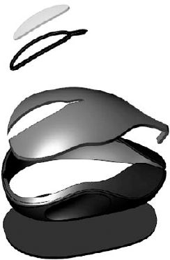
Figure 28.3 shows the FeatureManager of a part where the only feature is an Insert Part feature. All the solid bodies are listed under the normal Solid Bodies folder as well as under a second Solid Bodies folder under the inserted part icon. Other inserted items, such as surface bodies, planes, sketches, and axes, are also listed in folders under the inserted part icon.

You cannot be selective about which bodies are pulled forward, but you can delete unwanted bodies once they have all been brought in (using Delete Solid/Surface). If you are trying to handle data efficiently, this may not be the best option for you. Because you have to first bring forward all the bodies and then delete those you don't want, the body data is still stored inside the part. Remember that the Delete Bodies feature does not actually delete anything. It simply makes it inaccessible after a certain point in the part history. If you are inserting a part with many complex bodies, you may want to use a more selective method such as Insert Into New Part or Save Bodies, each of which I describe in more detail later in this chapter.
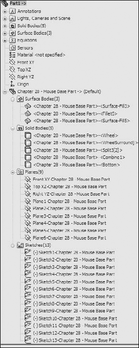
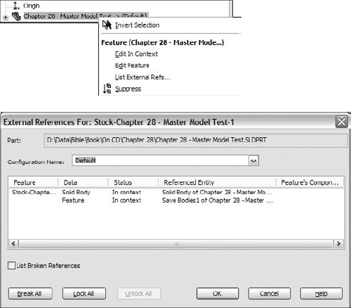
For the inserted part, you can set configurations of the parent document in the External References dialog box, which is available through the RMB menu of the feature that is inserted into the child document FeatureManager. The External References dialog box is shown in Figure 28.4. If the overhead of bringing many bodies forward only to be deleted is an issue for you, then you can use parent part configurations to delete the bodies first; then, from the child using List External References, you can select which configuration to insert.
As the original inserted bodies are modified by additional features in the child document, the names change, and they are removed from the folder under the inserted part and only appear in the body folders under the top level.
File management is a real issue with all these master model functions; in fact, it may not be an exaggeration to say that it is the biggest problem that arises with them, although you could say the same thing about overall body management. It is safe to say that you should be careful and follow file management best practice recommendations when performing name changes for documents with external references, especially if they use any of these features.
Insert Into New Part qualifies as a Pull function because it does not create a feature in the FeatureManager of the parent file, even though it is actually initiated from the parent rather than from the child. This function does not have a drop-down menu location, nor does it have a toolbar button. You can initiate it from the RMB menu from either the Solid or Surface Bodies folders or from the individual bodies within the folders.
This gives Insert Into New Part both advantages and disadvantages when compared to Insert Part. The advantages are that it can selectively insert either solid or surface bodies, or even selections of both types. You can Ctrl+select multiple bodies (solid and/or surface) to bring only the bodies forward that you need. However, it cannot bring forward planes or axes, or change the selection of what is brought forward after the feature is created. It also cannot be used to add a body to an existing part file; it can only be used to create new documents. This is definitely a good news/bad news situation, but with this information, you can make a more informed decision about which function to use.
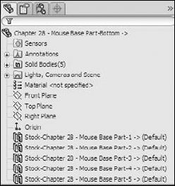
When Insert Into New Part is used to place bodies into a part, the bodies are not shown in the same way that the Insert Part function shows them. Figure 28.5 shows that the Stock feature symbols are used rather than the Inserted Part symbol given individual bodies are being placed rather than entire parts.
One note about this feature is that if it loses its referenced bodies, they cannot be reattached. An implication is that you cannot intentionally replace a body. Neither situation (lost references or the need to replace bodies) should come up frequently, if at all, for most users.
Push functions are initiated from the master model (parent document) and push data from the parent part out to a child part. A feature in the tree of the parent identifies the point at which the model is pushed out to the child, and the child file can be found from the parent.
The first feature in the child part is a Stock feature, and contains a reference back to the parent, so that the parent can be found from the child. The features that fall into this category are Split and Save Bodies. The bidirectional identification of the source and target of the feature holds a distinct advantage over the Pull functions, which do not allow you to identify the child from the parent document.
The primary function of the Split feature is to split a single solid body into multiple bodies. You do this with sketches, planes, or surface bodies, and I discuss it in depth in Chapter 26. The Split feature can save both the preexisting bodies and any bodies that result from the split as individual part files using the Stock feature as the initial feature in the part.
The ability to save solid bodies out to part files directly from the lower half of the Split PropertyManager has caused some serious file management problems in versions previous. In previous versions, if you add features to a part created by saving a body out from the Split feature, making changes to the Split feature could wind up overwriting the file with the additional features. Also changing the number of bodies going into the Split feature usually had bad effects on downstream data. Still some changes to the number of bodies (such as reducing the number of bodies, and then increasing it manually, undoing the original change) can still result in unpredictable behavior.
After you create the Split feature and you save bodies out of the Split feature, the RMB menu displays the Create Assembly option, which puts all the parts from the bodies in the original part back together in the correct positions. Parts within the assemblies created this way are fixed in space with the same relationship to the assembly origin that they originally had as bodies to the part origin.
Some of the concepts presented in this chapter may not make much sense until you apply them to a specific situation. The goal of this tutorial is to demonstrate the strengths and weaknesses of the various functions, as well as to give you some practical experience with the file management issues that you will encounter. You will use each of the four tools with the mouse multi-body part to become familiar with the differences in functionality. To get some experience with these techniques, follow these steps:
To work with the Insert Part function, follow these steps:
Make sure that you have access to the material from the CD-ROM for Chapter 28. Create a new part, and insert the part named Chapter 28 –
Mouse Base Part.sldprt. You can access Insert Part by choosing InsertAfter the feature is accepted and in the tree, right-click it and select List External Refs from the menu. The External References dialog box is shown in Figure 28.8, with the list of configurations displayed.
Save and name the part file in such a way that it has the name of the technique used to create it (Insert Part) and the name of the body that it represents (such as Wheel).

Note
I have done little bit of preparation work to make this tutorial flow more smoothly. If you ever choose to do modeling in this way, then you will need to know what this preparation work entails. In the mouse master model, I made a separate configuration for each body, and in that configuration, I created a Delete Body feature that deleted all the bodies except one. The alternative to this approach is to bring all the bodies into each new part, and use a Delete Body feature in each child part that deletes all but the one body that is needed. The advantage to using configurations is that bringing in a single body theoretically decreases the overhead for the individual part files.
Repeat Steps 1 through 4 for each of the five bodies in the master model.
If the mouse master model (Chapter 28 –
Mouse Base Part.sldprt) is open, then close it. In any of the child parts, the inserted part feature shown in the tree should have the Out Of Context symbol on it (- >?). Right-click the inserted part feature and select Edit In Context, which opens the master model.Notice that from the master model, you have no way of knowing where the child parts are or even if any child parts exist. Notice also that there is no easy way to create an assembly.
Create a new assembly document.
Drop all the individually created parts into the assembly by selecting them in Windows Explorer and dragging them onto the assembly Origin. This is probably the easiest way to create an assembly using the Insert Part feature.
Note
There is no link from the parent to the child; if the child part is renamed, the parent will not lose track of it. However, there is a link from the child to the parent; if the parent is renamed without the child being open at the same time, the child loses track of the parent. If the parent is changed, the child does not update unless the symbol is showing In-Context (->). If it is out of context, broken, or locked, the child does not update with the parent. Both documents need to be open at the same time to make the update happen (although they do not both need to be open when the original edit happens to the parent master model).
Save and close all the parts and assemblies.
To work with the Insert Into New Part function, follow these steps:
For this feature, start from the master model. Open the part Chapter 28 –
Mouse Base Part.sldprt. Make sure that the part is set to the Default configuration. If it is set to a different configuration, inserting bodies will not go as smoothly as it could.Expand the Solid Bodies folder in the FeatureManager. Right-click the first body in the list (Wheel), and select Insert Into New Part from the menu.
Note
You could select multiple bodies and even combine solid and surface bodies to insert using this technique.
When prompted, name the new part using the same convention used in the previous tutorial, which was to use the name of the technique (Insert Into New Part) and the name of the body. In this part, leave the configuration setting in the External References dialog box to the Default configuration.
Repeat Steps 1 through 3 for each of the bodies.
Right-click the Stock feature in the tree, and select Edit In Context. SolidWorks opens the master model part.
Note
Once again, there is no way back to the child document from the master model using the Insert Into New Part feature.
Create a new assembly document and use the same technique from the previous tutorial to put all the parts in the assembly located from the Origin. Again, no automated assembly creation tool exists for this method.
Save all documents and close them.
To work with the Split function, follow these steps:
This time, start from a copy of the master model part. The Split feature makes additions to the model, and because you have already created assemblies based on the original, any additional features should be created using a copy of the part rather than the original. Copy it using the Copy and Paste feature in Windows Explorer, and rename the copy as Chapter 28 –
Split Tutorial.
Note
It is best to copy and rename this document before continuing with the rest of the tutorial. Otherwise, you may encounter problems with the file references, from which it is difficult to recover.
With the newly copied and renamed document open, initiate the Split feature by choosing Insert
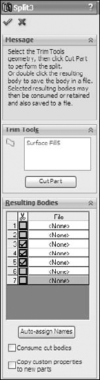
Because the bodies already exist, there is no need for the Trim tools or Cut Part functions in the Split feature, only for the resulting bodies. To save the bodies to individual files, you must give each one a unique name. You can click the Auto-assign Names button to automatically name them with the existing names of the bodies. It might be difficult to discern where the callout flags are pointing. Once the names are all satisfactory, click OK to accept the feature.
Note
The Consume Cut Bodies option deletes the bodies of any bodies involved in the Split feature. For most purposes, you should deselect this option. Deselecting the option makes sure that the bodies are still available after the Split feature. If what you are really looking for is to eliminate the bodies once they are saved out, then you should select the Consume Cut Bodies option.
To automatically create an assembly with all the components located in the proper location, right-click the Split feature in the Master Model FeatureManager, and select Create Assembly. Multiple Split features can be included in this command if bodies have been created by multiple Split features. Click the Browse button to locate and name the new assembly. Click OK when you are done. Completing this step opens the assembly that you just named and located. When you create the assembly, the parts will show up visually but may not be displayed in the FeatureManager until you have saved and reopened the assembly file. You should still have access to the data through the RMB menu from the graphics window.
Right-click one of the parts in the assembly to open it. Notice that a Stock feature is used in the tree, so it is possible to access the parent part and change the parent part configuration used in the current part. Right-click the Stock feature and select Edit In Context.
With the master model open, right-click the Split feature and select Edit Feature. From here, it is possible to see where each of the child parts is located.
If you rename any of the documents, then you should do this either by using SolidWorks Explorer or the Save As command with the other documents open as well. If you want to rename the parent part (master model), then make sure that all the child parts are open as well. (You can easily do this by opening the assembly; although the assembly was created from the master model, there is no direct link between the Split feature and the assembly.)
Save and close all the files before proceeding.
To work with the Save Bodies function, follow these steps:
As before, create a copy of the original master model part and rename the copy Chapter 28 –
Save Bodies Tutorial.Open the renamed copy, and right-click the Solid Bodies folder. Select Save Bodies from the menu. (Save Bodies has its own icon, which looks like the Split icon and is used to denote the placeholder feature in the FeatureManager.)
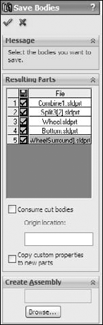
The Save Bodies PropertyManager is nearly identical to the lower section of the Split PropertyManager. Use it to save the solid bodies out to separate files. The major addition in the Save Bodies dialog box is that of the Create Assembly function directly within the PropertyManager. The primary benefit of this addition is that it retains the name and path of the assembly in this interface so you can look it up later if necessary, remedying one of the weaknesses in the Split feature.
Note
In both the Split/Create Assembly and Save Bodies features, when an assembly is created, SolidWorks may rebuild the tree of the part as many times as you have bodies to save out. This may take some time for a complex model with a lot of bodies.
After finishing Step 3, open the reconstructed assembly. Right-click one of the parts and select Open Part to open it in its own window. Notice that the Stock feature has again been used to push a single body into the part.
Right-click the Stock feature and select Edit In Context, which takes you back to the master model.
Save and close all of the files.
Each of these four functions has strengths and weaknesses. Because of this, there is no one feature that is clearly superior to the others in all respects. Most of the weaknesses have to do with the types of data that they can work with, the ease of creating an assembly, and access to children from the parents. Unfortunately, I cannot offer a single solution that addresses all the problems and retains each of the strengths.
The most important strengths, in my view, are the Insert Part and Insert Into New Part functions' capabilities to deal with both solids and surfaces. If you are working with surface bodies, you are forced into using one of these two functions. In particular, the Insert Into New Part function enables you to be selective about which bodies to pull into the child document. The other most important strength belongs to the Save Bodies feature, which makes the child accessible from the parent and identifies the assembly in the parent.
Why the various strengths of these tools cannot be consolidated into one or at most two different features or even how it's gotten to the point where so many different functions do approximately the same thing is a mystery to me.