In SolidWorks assemblies, mates are the basic units that either make everything work together and function properly, or fill the tree with errors and warning symbols. When properly handled, mates enable your assembly to react predictably to changes in parts exactly the same way that sketch relations drive changes in part features. As a result, mates and sketch relations often have the same function and even the same weaknesses to watch out for.
This chapter goes one step further with mates, by not just simply putting parts together with Coincident and Concentric mates, but also mating parts when tolerances, gaps, and symmetry become issues. You will also learn about the more advanced mate types that may be useful for special situations.
One of the assumptions that I make in this chapter is that assembly mates are not just used for positioning parts, but also for motion. Making motion work takes a little more than just establishing the right spatial relationship between parts; it usually also involves analyzing the open degrees of freedom.
From time to time, I have met users who take a static approach to putting parts together into assemblies, by simply placing parts at the correct X- and Y- coordinates without assigning any relationships to the parts around them. This defeats most of the purpose of creating parametric, associative assemblies in the first place. Assembly mates are an extremely powerful tool for enabling your assemblies to react predictably to change.
An average assembly of 100 parts is likely to have almost 300 individual mates. If you create these parts one at a time, taking perhaps a minute for each mate, you would spend five hours just applying mates. Any time that you can save applying mates is a benefit to you — assuming you still get the correct results — because it is time that you can spend doing something else. In this section, you will learn efficient mating strategies, as well as speedy techniques.
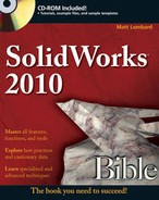
The Mate PropertyManager is the default method for applying mates, and was used briefly in Chapter 4. The Mate PropertyManager interface is shown in Figure 13.1. You can create mates by pre-selecting entities before applying the Mate command or selecting them after you open the Mate PropertyManager. The three types of mates are Standard, Advanced, and Mechanical.
If you make a lot of mates, it is important to have an efficient rhythm when working with the interface. Assuming you have the Mate PropertyManager already active, the most efficient way to use the Mate interface is as follows:
Click the first entity.
Click the second entity.
Click OK on the right mouse button (RMB) cursor icon to accept the default.
Or, if the automatic default mate type is not the mate that you want to apply, select it from the popup list, which is shown in Figure 13.2.
Click the green check mark icon from the popup list.
Repeat Steps 1 to 4.
After the last mate, press Esc, the green check mark icon, or the red X icon from either the PropertyManager or the confirmation corner in the upper-right corner of the graphics area.
Sometimes you will have to rotate the model to achieve the correct view in order to select faces or edges. There are also times when you will want to pre-position so that the model snaps into the correct position automatically. You can rotate individual parts in an assembly by clicking and dragging with the RMB. (Dragging the RMB over a part rotates that part). You rotate the view by dragging with the middle mouse button, or MMB. You can move parts by dragging them with the left mouse button, or LMB. You can pan the view by pressing Ctrl and dragging with the MMB. When you drag a part with the LMB while the Mate PropertyManager is active, SolidWorks does not add the selected entity to the Mate Selections list.
To summarize these actions:
To rotate an individual component in an assembly, click and drag with the RMB.
To move an individual component in an assembly, drag with the LMB.
To rotate an assembly view, drag with the MMB.
To pan an assembly view, Ctrl+drag with the MMB.
Also be aware of the view manipulation tools, available by clicking the triad in the lower-left corner:
To rotate normal to an axis, click its triad axis.
To rotate by 15° about an axis (angle can be specified at Tools

To rotate by 90° about an axis, Shift+click its triad access.
To activate the mouse gesture wheel, drag the RMB in blank space (dragging the RMB over a part rotates the part).
To zoom to fit, double MMB-click in the graphics window (same as the F hotkey)
The Select Other command enables you to select items that are hidden by other items. It is often used to select faces that are hidden behind other faces without rotating the part. You can apply the Select Other command through the RMB menu. Right-click where the face would be if you could see it. A list of entities displays and you can select the entity you want from this list or from the graphics window.
Moving your mouse over an entity in the list highlights the entity in the graphics window. Pressing Tab or scrolling the mouse wheel cycles through the entities one by one. Clicking faces with the RMB hides them, which enables you to see further down into the part or assembly. Clicking with the LMB either in the graphics window or the selection list box selects the item. Figure 13.3 shows the Select Other cursor and dialog box.

Although this selection method is also used for other purposes, it is often used for selecting faces for mating.
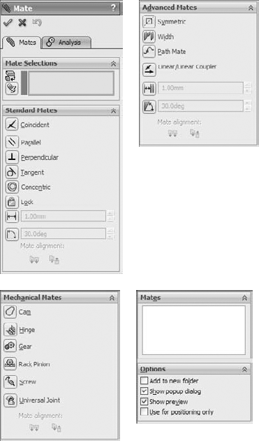
You can create a special folder for all the multiple mates by selecting the Create multi-mate folder check box in the Mate Selections PropertyManager. You can also automatically link the values for distance and angle mates with link values by selecting the Link dimensions check box.
SmartMates are mates that you can create automatically by dragging one part onto the other without invoking the Mate command. There are three different methods that you can use to apply SmartMates:
Probably the easiest way to quickly create a SmartMate is by Alt+dragging. One, two, or even three mates can be applied at once by holding down the Alt key while dragging a face or edge from one part onto a face or edge on another part.
When you are dragging a part while pressing the Alt key, the part is made transparent to enable you to see other part faces that you may want to mate it to. A special cursor appears when a SmartMate is about to be applied. Figure 13.5 shows the cursors that appear for adding Concentric and Coincident mates.
When you drop the face or edge onto the mating face or edge to complete the mate, you must use the popup Mate toolbar to accept or alter the mate. In the examples in Figure 13.6, a face is being dragged onto another face. However, you can also drag edges and vertices. Mates are limited to being either Coincident or Concentric.
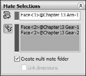
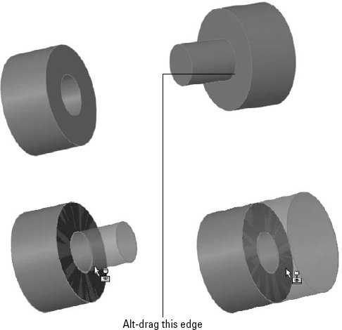
The peg-in-hole mate is actually the combination of a Concentric mate and a Coincident mate. This is the type of mate that is created between a screw and a hole, and is the result of Alt+dragging a circular edge onto a circular edge. When the circular edges are created by the intersection of a cylindrical face and a flat face, the Concentric mate goes between the two cylindrical faces, and the Coincident mate goes between the flat faces. The peg-in-hole mate is illustrated in Figure 13.6. The top two images show the state of the parts before the SmartMate. The image in the lower left shows the SmartMate orienting the part in the wrong way so that the two parts interfere. In the image in the lower right, the part to which the SmartMate is applied has been reoriented by the Tab being pressed before the SmartMate is accepted by the part being dropped.
Tip
You can press the Tab key to flip the alignment if a SmartMate tries to put parts together in the wrong way. If you are in the process of Alt+dragging, make sure to release the Alt key before pressing Tab. The Alt+Tab combination is a Windows shortcut to show a list of open applications.
You can simply Ctrl+drag a face of the part to the face of another part in a different SolidWorks window. It is probably most useful to tile windows before creating this kind of SmartMate.
Mate references are model faces, edges, or vertices that are pre-selected and used in a SmartMate-like fashion when a part is dragged in from Windows Explorer or from a library window. Mate references are discussed in Chapter 19 in the course of discussing library parts. They are a great way to automate common mates with commonly used parts, such as library parts.
If all the confirmations and extra mouse-clicks to open and close windows are not for you, and you are just applying simple mates, then you may want to use macros to mate parts. Macros are not going to give you the same flexibility, but for simple and predictable mates, they do vastly improve speed. You have to have the parts ready to go when you press the macro button, or you will create the wrong mate.
You can find macros for Coincident, Concentric, Parallel, Perpendicular, and Tangent mates in the CD-ROM folder for Chapter 13. For example, to use the concentric macro, you would need to pre-position the parts so that they are within 90 degrees of the proper alignment, have one of the parts mated in place such that that only one part will move, select the two cylindrical faces, and then run the macro. Ideally, the macro would be connected to a hotkey, so the workflow for this process would be extraordinarily fast. You would click one face, click the other face, then press the hotkey, and the parts would fly together.
Note
To connect a macro to a hotkey, first put the macro in a folder called macros under the SolidWorks installation directory, and then restart SolidWorks. Then use the Keyboard dialog box (Tools
Like SmartMates, macros work best for the simpler mate types where you do not need to select any options. The workflow with macros can be very fast, but you have to have the parts pre-positioned and be very sure of what you want.
Dynamic Assembly Motion is a powerful tool for visualizing the motion of mechanisms in SolidWorks. It works best if there is a single open degree of freedom.
When working with motion in SolidWorks, you need to be comfortable with the concept of degrees of freedom. When inserted into an assembly, each model begins with six degrees of freedom:
Translation in X (tX)
Translation in Y (tY)
Translation in Z (tZ)
Rotation about X (rX)
Rotation about Y (rY)
Rotation about Z (rZ)
When applying mates, and especially when troubleshooting motion or overdefinition problems, it is important to look at how each mate translates into degrees of freedom being tied down. For example, a Coincident mate, planar face to planar face, ties down one translation degree of freedom (in the direction perpendicular to the faces) and two rotational degrees of freedom (about directions which lie in the plane of the faces). What remains are two translational degrees of freedom in the plane of the faces and one rotational degree of freedom about an axis perpendicular to the planar faces.
A point-to-point Coincident mate ties down three translational degrees of freedom, and the part can only rotate.
An edge-to-edge Coincident mate ties down two translational and two rotational degrees of freedom. As a result, a part that you mate in this way can only slide along the mated edge and rotate around the mated edge.
Tip
When using face-to-face Coincident mates, it takes three mates to fully define a block type part. When using edge-to-edge Coincident mates, it only takes two mates.
Something to be careful about is that a degree-of-freedom analysis frequently predicts an over-defined mate scenario when SolidWorks does not in fact display any errors or warnings. For example, if one block is mated to another with the simple case of three face-to-face Coincident mates, and each Coincident mate ties down one translational and two rotational degrees of freedom, then the mating scenario ties down 9 degrees of freedom, so the part is overconstrained by three rotational degrees of freedom. However, SolidWorks has a lot of forgiveness built in, so it frequently allows situations like this, where parts are severely overconstrained. When troubleshooting any overconstrained situation, you should not take this forgiveness for granted. If SolidWorks reports an assembly as overconstrained and the reason is not intuitively obvious, try reducing some of the degrees of freedom constrained. For example, instead of making two faces coincident, consider making them simply parallel, or mate a point to a face instead of two faces.
This may be an overly cautious approach, but it can mean the difference between an assembly that works and one where errors are frustratingly persistent. If you are careful to approach all parts with the degree-of-freedom analysis in mind such that any newly added mate does not duplicate any of the degrees of freedom that are already tied down, you will have fewer assembly mate errors and fewer problems with assembly motion.
This means that instead of having the traditional three face-to-face Coincident mates, you would have one face-to-face Coincident mate (one translational degree of freedom, two rotational degrees of freedom), one edge-to-face Coincident mate (one translational degree of freedom, one rotational degree of freedom), and one point-to-face Coincident mate (one translational degree of freedom). This accounts for three translational and three rotational degrees of freedom without over-defining any of them.
It is true that SolidWorks internally compensates for over-defined degrees of freedom, but relying on it to do so and then tempting fate by methodically over-defining all assemblies is a risk that you do not have to take, even though it is common practice.
The best bet for creating motion in a SolidWorks assembly is to leave open a single degree of freedom. This means that there is only one way the part can move, back and forth, by translation or rotation. Computers in general do not respond well to ambiguity. Dragging an item that might move in several ways is more likely to cause jerky or hesitant motion.
A good example of this kind of problem with motion can be found in one of the sample assemblies that installs with SolidWorks. I have included this example on the CD-ROM for your convenience, and it is shown in Figure 13.8. The filename for the assembly is Plunger.sldasm.
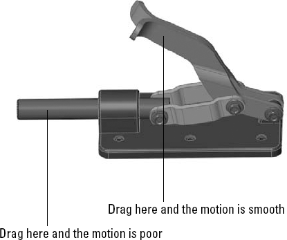
If you drag the assembly parts from the location shown in Figure 13.8, the performance varies. This is because when you drag the handle parts, for every position of the handle, there is only one solution for the rest of the parts. However, when dragging the plunger bar, for every position of the plunger bar, there are two possible positions for both the links and the handle (one possibility is as shown, and the other would be with the handle interfering with the base of the assembly). This kind of ambiguity causes problems in SolidWorks assemblies such as assemblies that have open degrees of freedom but will not move or only move in a jerky fashion.
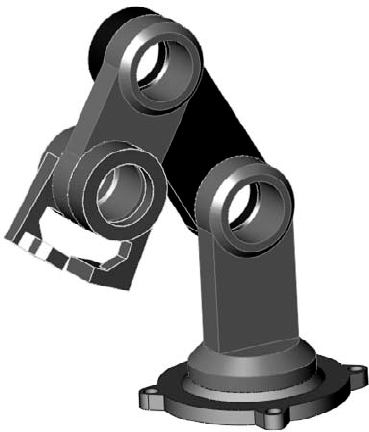
Another example of difficulties related to open degrees of freedom and motion is shown in Figure 13.9. The grippers at the end of the arm move when the rest of the arm moves, but the grippers cannot be independently controlled by dragging. To fix this problem, you may want to either use the Fix/Float option (available through the RMB menu) or use configurations with mates suppressed or unsuppressed. Fix the part that you want to remain stationary closest to the part you want to move. Remember to Float the part when you are done. Be aware also that fixing a part may over-define some mates. You can open this assembly from the CD-ROM, in the filename called Chapter 13 Robot Assembly.sldasm.
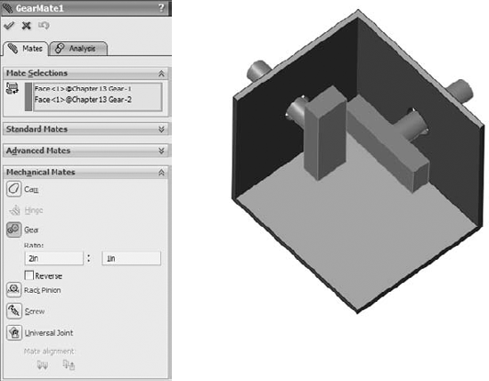
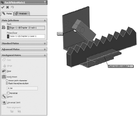
Advanced and Mechanical mate types greatly expand the number of ways that you can put parts together into assemblies. Advanced mate types include Symmetric, Width, Path Mate, Linear Coupler, Limit, and others. Mechanical mate types include Cam, Hinge, Gear, Rack and Pinion, Screw, Universal Joint, Belts /Chains. You can access Advanced and Mechanical mates by expanding the corresponding panels on the Mate PropertyManager shown in Figure 13.1.
Coincident. The vertex on the follower mated to a cam that is created from a single closed-loop face (spline, circle, ellipse).
Tangent. The cylindrical or planar face mated to a cam that is created from a single closed-loop face.
CamMateCoincident. The vertex on the follower mated to a cam that is created from multiple faces. This condition enables the follower to go all the way around the cam, not stopping at the broken faces or following the extension of a single face.
CamMateTangent. The cylindrical or planar face mated to a cam that is created from multiple faces. This condition enables the follower to go all the way around the cam, not stopping at the broken faces or following the extension of a single face.
Figure 13.11 shows both single-face and multi-face cams, along with the Cam Mate interface. The two assemblies are available from the CD-ROM in the file named Chapter 13 Cam.sldasm.

If you open the assemblies and spin the cam plate, you will notice that in both cases, the flat follower does not work very well. In fact, in the single face cam assembly, it does not work at all.
Note
Barrel (cylindrical) cams cannot use the Cam mate to create cam motion, but they do work with the Path mate. Path mates are covered in more detail later in this section.

On the CD-ROM, open the assembly named Chapter 13 Robot Limit Mate.sldasm. Drag the Robot Tower part. Notice that it only rotates within a limited angle. LimitAngle2 is the mate that is driving this motion.

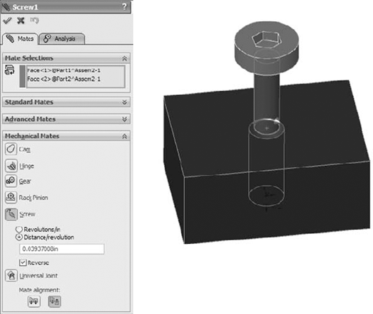
Screw mates can be handy for lead screw animations. I would probably not recommend them for general modeling, but for animations, they are a fantastic addition to the mate toolbox.
Note
On the barrel cam in Figure 13.17, notice that a sketch point is being driven along the path. In reality, this does not exactly reflect the motion of the follower around the cam surface. The Path mate does not take into account the tangent contact point between the surfaces; it simply drives the point along the curve. There is a slight amount of error in this scenario, such that the leading or trailing surface of the follower will interfere with the cam, depending on the angle of the cam surface. Also note that the Path sketch entity has nothing to do with the Path mate; it is not required to make the Path mate work.

You can use this mate to simulate symmetric motion, or geared motion without modeling the rest of the detailed mechanism. Figure 13.18 shows the setup for this mate.

Chapter 4 has a tutorial that discusses the Belt/Chain functionality as it relates to sketch blocks. The functionality using solid parts as pulleys and sprockets is very similar. You can initiate the Belt/Chain function from a toolbar button on the Assembly toolbar or through the menus by choosing Insert

You should become proficient with editing and troubleshooting assembly mates. If you are not comfortable with repairing and modifying mates, you may find assemblies frustrating to work with. However, once you master the techniques, you will be more confident and willing to experiment with assembly changes.
If you are editing just one mate, then you can simply right-click it and select Edit Feature (or if you are using Context Toolbars, left-click it and click the Edit Feature button). Remember that you can find mates in places other than the Mates folder at the bottom of the assembly FeatureManager; most notably, you can find them in folders under the parts that they are mating together.
You can make several types of changes to mates, including changing the selections, the mate types, and the mate alignment. These types of changes are all shown in Figure 13.20, which displays a mate being edited. The selected faces are highlighted in the graphics window.
To edit multiple mates consecutively without exiting the Mate PropertyManager, it is best if you pre-select the mates. Pre-selected mates are shown in the Mates panel, as shown in Figure 13.20. You can switch from editing one mate to another by simply selecting the new mate in the Mates panel. If you select only one mate before clicking Edit Feature, but realize later that you want to edit multiple mates, you can select more mates through the FeatureManager.
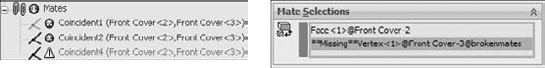
When mate entities are lost, the mate displays as grayed out, as shown in Figure 13.21. Also shown is a mate that cannot be resolved; for example, a face coincident to two points separated in space. You can repair the missing reference problem by selecting the Invalid reference in the Mate Selections window and then selecting the correct item from the graphics window.
The yellow triangle is a warning symbol that shows that a mate is satisfied, but it is in conflict with another mate that is not satisfied.
It is best to troubleshoot an assembly mate problem as soon as it appears, and not after it has time to become complicated by other issues. Failed mates also cause performance problems because SolidWorks keeps trying to solve the mates that are in conflict with one another.
Assembly problems often appear to be far larger than they actually are. For example, the entire tree may light up with warnings and error symbols when one extra mate is applied. You can use several approaches to troubleshoot situations like this. In fact, I sometimes purposefully over-define mates just to locate a leftover mate or a mate that is not supposed to be there.
Two types of symbols may help you distinguish the kinds of errors that are present in different mate features. The yellow triangle that contains an exclamation point is really not an error; it is actually more of a warning. It tells you that this mate is in conflict with other mates (this symbol is used for a variety of warnings), but that the mate is still satisfied. One of the other mates with which it conflicts is probably not valid, and so this type of warning is usually accompanied by an actual error symbol where the mate is not satisfied.
The red circle containing the X is a failed mate. This is a mate that is in conflict and is invalid. If it is also a Coincident mate, then the two Coincident entities are not coincident.
You can use the following troubleshooting techniques:
Last in first out. When a mate is added that causes warning and error signs to appear throughout the design tree, you can usually correct the problem by removing this last mate.
Single elimination. If you are sure that the last mate added is correct, then you may want to go backward up the tree starting at the bottom, suppressing individual mates until you find one that causes the warning and error signs to disappear from the tree.
Single addition. It may be easier to take the opposite approach, by suppressing all but the mates that you are sure of, and then gradually unsuppressing mates until the conflict reappears.
Suppress a part. With all the mates active, try suppressing an individual part to see whether this makes a difference. If it does, then unsuppress the part and look at the mates for that part in the Mates folder under the part.
Mate Xpert. The Mate Xpert is an automated routine that creates subsets of groups of conflicting mates. Each subset of mates has one mate that is not satisfied because of the conflict. This may help you to find the cause of the conflict. Figure 13.22 shows the Mate Xpert interface. You can access the Mate Xpert from the RMB menu on mates with errors.

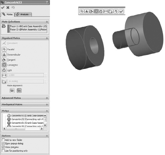
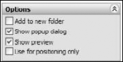
The Options pane of the Mate PropertyManager is shown in Figure 13.23. Most of the options are self-explanatory, except for Use for positioning only. This option positions a part but does not apply a parametric mate. Some users make extensive use of this option for various applications where you need the part located precisely, but do not need or want a mate feature in the tree. Positioning parts for Animator animations where the part does not move according to a mate is one example of a use for this option.
Sometimes best practice recommendations can contradict one another, and for each best practice recommendation that you find, there are likely several specific situations where the recommendation is invalid. As a result, you should apply the following recommendations carefully.
Each assembly should have at least one part that is either fixed or fully mated to the standard planes of the assembly so that it cannot move relative to the assembly.
You should use fixed parts sparingly. One part that serves as a "ground" for the assembly should be fixed. Other than that, the parts of imported assemblies are sometimes fixed to keep them from being moved accidentally.
Do not mate to time-dependent features in the assembly tree, or to in-context features in parts. You may want to refer to Chapter 12 for a refresher on time-dependent features in the assembly tree. This can create circular references where the assembly must be rebuilt multiple times to fully resolve the positions of all parts and sketches.
When possible, it is best to mate all parts to the "ground" part. Creating daisy-chain mates (where A mates to B, which mates to C, and so on) forces the mates to be solved in a particular order, which may take more time to solve than otherwise. If all the mates relate to established assembly references, the mates may be more stable. Chapter 11 describes using a skeleton in a part to make sketch and feature relations. A similar concept can be applied in an assembly, by mating parts to an assembly sketch.
When possible, leave part positions fully defined, especially when other geometry is dependent upon the position of parts. Some examples include in-context features, assembly features, or assembly-level reference geometry, which are dependent on part geometry.
Constraining the rotational degree of freedom for components such as screws, washers, and nuts is usually considered excessive. At times, too many open degrees of freedom may cause problems with complex motion, such as a gripper on the end of a robotic arm. SolidWorks functions well when there is a single, well-defined path between two points, but when there are multiple options, the software may become confused.
Do not leave errors unresolved in the tree.
Remember to use subassemblies to break up the number of mates that are solved in the top-level assembly.
Limit the use of flexible subassemblies.
Do not mate to entities that may be removed later by suppressing or unsuppressing features, especially edges or faces that are created by features such as fillets. For this reason, it is usually best to wait until parts are complete before you use them to create an assembly, although this is rarely practical.
Use a degree-of-freedom analysis to prevent mates from becoming over-defined.
In this tutorial, you will put together a model of a robotic arm to better understand some of the mate issues discussed in this chapter. Follow these steps to mate for success:
Open the part named Chapter 13
Robot Base.sldprtfrom the CD-ROM.

Open the part with the filename Chapter 13
Arm.sldprt, the Default configuration, in its own window, and choose WindowClick the face inside the hole without the chamfer around it in the Arm part, as shown in Figure 13.25. Then drag it into the assembly to the cylindrical face inside the hole at the top of the Robot Tower part. The concentric SmartMate symbol should appear on the cursor.
Click the green check mark icon to accept the Concentric mate. Move the part to test that the mates are correct.

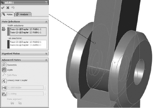
In the Width Selections box, select the two inner faces of the Robot Tower part, and in the Tab selections box, select the outer faces of the Arm part. The selection should look as shown in Figure 13.26.
Open a Windows Explorer window, and select the following parts: Chapter 13 Robot Arm2 and Chapter 13 Robot Gripper. Drag these parts into the SolidWorks assembly window and drop them in a blank space.
Select the chamfered faces of the Arm and Arm2 parts and create a Coincident mate between them. You can make Coincident mates between conical faces as long as the cones are the same angle. This special case acts like a combination of Concentric and Coincident mates. Figure 13.27 shows the selections and the results.
Create a copy of the gripper part so that there are two instances of it in the assembly. You can do this by Ctrl+dragging the part within the assembly window with the Mate PropertyManager closed.
Mate both of the grippers to the Arm2 end using the same mating technique that you used for the previous conical face Coincident part.
Once you have applied these parts, try moving the various joints of the assembly. Notice that it is difficult, if not impossible, to isolate the motion of just a single part. This is because there are too many open degrees of freedom, and a lot of ambiguity.
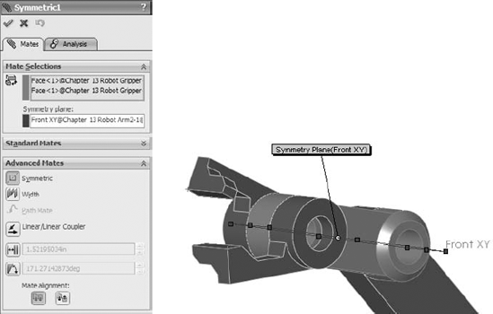
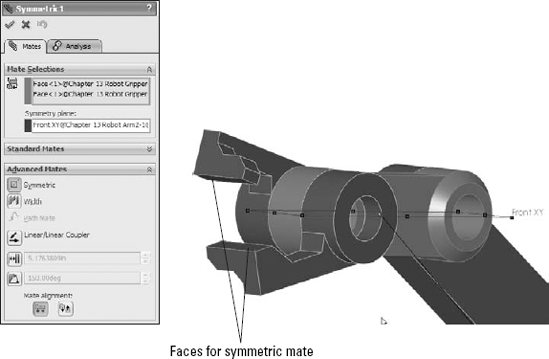
Fix Arm2 to allow you to move the gripper parts as you want. Create a Symmetric mate between the indicated faces of the grippers and the Front plane of the Arm2 part, as shown in Figure 13.28.
Practice making angle mates, suppressing mates, and fixing parts to limit motion.


A thorough understanding of mates, and editing and troubleshooting techniques in particular, makes the difference between a real assembly artist and a user who struggles through or avoids certain tasks. There is a lot about mates that is not straightforward, but with practice, you can understand and master them. You can put assemblies together quickly, with a focus on rebuild performance and Dynamic Assembly Motion.
Although best practice concepts should not dominate your designs, they are great guidelines to start from. Watch out for the pitfalls outlined in the section in this chapter that summarizes mate best practices to follow to avoid making big mistakes.