
You get multiple bodies in SolidWorks when you have simultaneous separate enclosed volumes within a part. It can be useful or problematic. Multi-body parts are not inherently good or bad, but depending on how you use them, they can mean either good news or bad news. This chapter will show you how to use them carefully to get the most benefit and avoid typical problems.
You could work with SolidWorks in such a way that you would never need to use multiple bodies inside a single part, ever. Almost everything that average users normally do can be done with a single solid body and without any knowledge of multi-body functionality whatsoever.
However, to access some more powerful functionality, and options that offer more flexibility, multi-body modeling is necessary. In fact, if you want to move on to surface modeling, multi-body knowledge is mandatory because in surface modeling, multi-body is the default.
Multi-body modeling is the gateway from basic solid modeling mainly described in the book up until now into the more advanced functionality that follows. The gateway can lead in two directions: it can lead to more power, more flexibility, more options, more advanced functionality, or it can lead to sloppy, bad habits that could get you or those who work with your data into some modeling hot water down the road. This chapter will help you tell the difference and avoid the pitfalls.
I find myself giving the same responsible-modeling advice when discussing multi-bodies as I tend to give for in-context modeling and virtual components. This is because multi-bodies present some of the same issues as in-context modeling. The first similarity is that on the surface, both techniques appear to be all-day-every-day types of design tools. The second similarity is that there is more to the story than what initially appears.
The responsibility part arises when you are thinking about the users who will use the multi-body parts once they are created, including yourself. It is not always easy to remember how you executed a particular project 6 months and 100 models ago. Other users may have to edit your work, and if errors happen, then you have to be able to navigate the design intent without destroying the relationships in the FeatureManager or completely rebuilding it. This is the reason for trying to standardize best-practice issues, particularly with advanced functionality and particularly in larger organizations where more users may work with the data.
If you are an independent contractor and do not share your models with other SolidWorks users, then you have more flexibility to model how you like. As long as you can come back to the model and change it when you need to, more power to you.
This concept is important, and so I will repeat it: Multi-body modeling is not assembly modeling. Many times when new users are introduced to the capabilities of multi-body modeling, the first thought that comes to mind is, "This is far easier than making assemblies." However, multi-body modeling should not be treated as a replacement for assembly modeling.
Several assembly type functions are missing or more difficult to obtain from multi-bodies. They include the following:
Interference detection
Dynamic assembly motion
Exploded views
Configs for separate parts
Drawings for individual parts
Center-of-gravity calculations for individual parts
Mass property calculations for individual parts
To say that these functions are missing from or difficult in multi-bodies does not imply that they should or will be there someday. In fact, I believe that the distinction between multi-body and assembly modeling techniques should be kept as clear as possible. Simply because a technique is easier does not make it better. Above all, remember that modeling multi-body parts puts all the data for all the bodies in a single part file, in a single FeatureManager; there is no easy way to separate out the parametric features into individual parts later on, regardless of how complex the part becomes.
You may find parallels between making multi-body parts and making virtual components (parts that are saved within an assembly file). While both these techniques offer shortcuts or make some basic tasks easier, good reasons exist for being mindful of the "one part, one file" mentality, including:
Segmenting rebuild times (the ability to rebuild one part instead of several)
Segmenting large data sets (being able to work on one part at a time)
Switching out parts
Reusing parts
Bills of Materials (BOMs)
Further, creating drawings of individual bodies of a multi-body part is more difficult than creating drawings of individual parts, not that it cannot be done (remember that starting in SolidWorks 2010 you can now specify bodies from a part to be used in a drawing view), just that it is more difficult. Also, editing the features of individual bodies is not as easy as if the individual body were an individual part. When you create several bodies in a single part, you constantly have to carry the feature and design intent overhead of all the features used to create all the bodies to edit any individual body.
You need to have a healthy respect for the problems that you can create for yourself and others by using multi-body modeling in inefficient or inappropriate ways. Still, appropriate uses for multi-body modeling do exist. You may hear people recommend that at the end of the FeatureManager, only a single solid body should remain, with the rest of the bodies either absorbed or deleted. On the other extreme, for some people, anything they can create is allowable. I recommend that if you decide to use multi-bodies, then you should be at least able to articulate why you have chosen to do so in a way that does not sound like you are making excuses for careless work.
Appropriate uses for multi-body modeling include (but are not limited to):
As an intermediate step on the way to a single-body solid.
As multiple or inserted bodies for reference (reference bodies may be deleted at the bottom of the FeatureManager).
As over-molded parts.
As parts that need to be assembled into a single, smooth shape, such as a computer mouse or an automobile body where the shape is impossible (or at least far more difficult) if done in-context.
When the end shape of the finished product is known, but the part breaks due to manufacturing methods, and materials have not been decided yet, multi-body techniques can save a lot of time compared to modeling an assembly.
As captive fasteners and purchased inseparable subassemblies.
When SolidWorks weldments result in a single multi-body part.
When features require tool bodies, such as the Indent feature.
When the Mold Tools result in a single multi-body part representing the plastic part and the major mold components.
If you are administering a SolidWorks installation of multiple users, then you may be looking for a "bright line" test to clearly define for users which types of multi-body modeling are allowable and which are not. So many possibilities exist that it is difficult to say definitively what really should not be done, but here is a short list that you can modify for your needs:
Do not use multi-body modeling simply to avoid making an assembly — you must be able to cite a specific reason for using the technique.
Do not leave a part in a multi-body state that should be joined together into a single body.
Hiding a body is sometimes appropriate, and deleting a body is sometimes appropriate — understand the difference.
Okay, the lecture is over. The message that you should take from all this is not to use multi-body techniques just because you can; use them only when you have a solid reason to do so. I do not say this because I am the design police; I say this because it is the criterion that I use for my own modeling, what I would like to see in models that I inherit from other SolidWorks users, and a philosophy that will serve you well if you are conscientious about it.
Multi-body modeling is powerful, and for complex parts can even increase rebuild speed compared with single body modeling or assembly modeling. You can develop and use many powerful techniques based on multi-bodies, but as I mentioned earlier, as can be true for in-context and virtual components, sometimes you pay a price for the short cut.
To complicate the issue somewhat, nearly all surface modeling is also multi-body modeling. In this chapter, I am referring to solids unless I specifically state otherwise. Still, most solid body techniques have some sort of equivalent in surface body techniques. Surface bodies are discussed in Chapter 27.
Multi-body techniques cover a wide range of functionality, and as soon as someone creates a list of what you can do with them, someone else will come up with a new technique. Still, here is a short list of techniques where multi-body functionality makes things either easier or simply possible:
In the remainder of this chapter, I illustrate each technique using an example model, and discuss the positives and negatives of each technique. As you get deeper into SolidWorks, you will find that the more complex functions tend to come at a price. A given feature might be the only way to accomplish a particular task, but it rebuilds slowly, might only work in special conditions, might crash from time to time, or might not make sense to other users if they have to edit it.
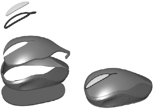
When creating a part such as a computer mouse, you encounter complex shapes that span several parts. It makes the most sense to model the entire shape as a single part, and then to break it up into separate bodies, making parts from the bodies, adding detail to individual piece parts, and then bringing the parts back together as an assembly.
Cross-Reference
This method also uses the Master Model techniques discussed in Chapter 28.
A part that uses this technique is shown in Figure 26.1. This part seems to contradict what I said earlier about not being able to use exploded views with multi-body parts, but this part uses the Move/Copy Bodies feature to move bodies within the part. This function remains in the part as a history-based feature in the FeatureManager and is much more labor-intensive to create than an assembly exploded view because each body is moved by a separate feature.
The part shown in Figure 26.1 is not complete, but the starting point for each part has been formed. This part was created from surface features that are discussed in detail in Chapter 27. The part is named Chapter 26 – Mouse Base Part.sldprt and is located on the CD-ROM. You may find it interesting to open the part to see how it has been modeled.
From here, each body is saved out to individual parts to complete the detailing, and then the parts are brought back together to create an assembly. The separate bodies in this case were created using the Split feature, which enables you to use surfaces or sketches to split a single body into multiple bodies. This is described in more detail later in this chapter.
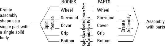
The entire process for creating a finished assembly of finished parts is detailed in Figure 26.2. This flow chart shows conceptually how the overall shape created as a single part has moved from a single part/single body to a single part/multiple body to individual parts to an assembly of individual parts.
The image to the left in Figure 26.3 depicts how this part was modeled. The first step was to create the shape as a single body within the part. As shown in the FeatureManager, this is all contained inside the Overall Shape Features folder. This folder is presented here as a black box because surface features were used to create the part. It really doesn't matter at this point how the part was created, and these features are not discussed until Chapter 27.
The image to the right in Figure 26.3 shows transparent surface bodies that were used to split the model into separate bodies using the Split features shown in the tree. Using this technique, you can create the overall shape as a single piece and then split it into separate parts. It is also possible to apply this technique in the context of an assembly, but this method is far more direct.

To go from the multi-body part created here to a set of separate parts uses a Master Model function, which is described in Chapter 28.
Some features require multiple bodies within a part, such as the Indent and Combine features, among others. Using one body to create a shape in another is a common use for bodies within a part.
Figure 26.4 shows the target part as transparent, and the tool as opaque, before and after the Indent feature has been applied. The Indent PropertyManager is also shown.

On the CD-ROM
To take a closer look at this part and the Indent feature, look at the part on the CD-ROM named Chapter 26 – Indent Part.sldprt.
The Indent feature can be problematic if it breaks into multiple areas as it does in this part, due to the ribbing on the underside of the target body. Notice that in the PropertyManager in Figure 26.4, two selections were made in the Tool body region selection box. The tool body is selected on either side of the rib that bisects the tool. This concept is not very intuitive, and you may have to play with the part and the options to understand what it is doing.
The Keep selections and Remove selections options are equally unintuitive, but they determine which side of the target body is indented. For example, if the part of the tool body that is outside of the target body (flat side) were selected instead of the two inside regions, then the resulting part would look as it does in Figure 26.5, where the tool body has been hidden. You can achieve the same result by toggling the Keep selections and Remove selections options. These options exist because sometimes it is difficult or impossible to select the correct areas of a body that is embedded in another body.

Tip
Also notice that toggling the Keep and Remove selections options means that only one region of the tool body needs to be selected to create the original result shown in Figure 26.4.
Figure 26.6 shows the starting and ending points of the process, as well as the PropertyManagers of the two features used to get from one point to the other. Keep in mind that both the Move/Copy Bodies and the Combine features are history-based features listed in the FeatureManager.
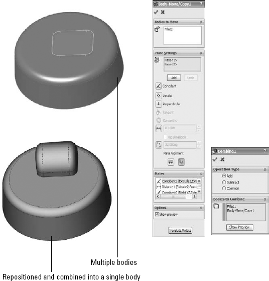
In this case, the Move/Copy Bodies feature uses mates. These mates enable you to locate bodies in a way similar to the way they are used in assemblies. One important difference is that with bodies, you must use the actual body geometry of the body that is moving; you cannot use reference geometry such as planes. By clicking the Translate/Rotate button at the bottom of the PropertyManager, you can also position bodies using distances and angles.
In the Combine PropertyManager, you will notice that common Boolean operations, such as union (add), difference (subtract), and intersection (common), are available through this interface.
Tip
You can use an interesting technique in this part. The features creating the smaller tool body and the Move/Copy Bodies and Combine features can be put together into a folder, and the folder itself reordered before the Shell feature. This means that the combined body is also shelled out, and the rib goes down inside of it. This produces an odd error message and unexpectedly places several features into the folder, but it does work.
You may want to open this part in SolidWorks to see exactly how all this was done instead of relying on the figure illustrations. The part used for Figure 26.7 is on the CD-ROM and is named Chapter 26 – Move Body.sldprt.

If you have ever had a modeling situation where you needed to shell out a portion of a part but not the entire part, or you had a fillet that would work if only certain geometry were not there, then you may have been able to benefit from multi-body techniques to accomplish these tasks.

The Multi-thickness Shell option enables you to select faces that will have a different thickness from the overall shell thickness. This is one method that you can sometimes use to limit the scope of the Shell feature to a certain area of a body, but it is somewhat limited. Faces with different thicknesses cannot be tangent to one another.
Because the Shell feature only works on one body at a time, splitting a part into multiple bodies can be an effective way to limit the scope of the feature. The part shown in Figure 26.9 has been split in half, and one-half has been made transparent for visualization purposes; as a result, you can see that the part is shelled on the bottom on one end and on the top on the other end. The Shell feature has no option for doing this with existing geometry. The only ways that you can do this are either through feature order or by using multi-bodies. You can find the part shown in Figure 26.9 on the CD-ROM with the name Chapter 26 – LocalOps Shell.sldprt.
To shell the part this way with feature order, you create one block and shell it, and then create the other block and shell that. In order for this technique to work, the second shell needs to be as big as, or bigger than, the first shell. If it is smaller, then it will (or may) hollow out areas that are not intended to be hollow.

To shell the part with multi-bodies, you can use two methods. One method is to build the first block, and then build the second block but turn off the Merge option. This creates bodies that are side by side. You then shell one block on the bottom and the other on the top. To avoid a double-thickness wall between them, the end face can be removed along with either the top or bottom face. If you edit the part, then you may notice that one of the Shell features has two faces removed.
The second method is to build a single block, then split it using a sketch line, a plane, or a surface, and then proceed in the same way as the first method.
Patterns of bodies are fast, powerful, and commonly used alternatives to patterning features. Chapter 8 discusses feature patterns and mirroring, and examines, at least in part, how different types of patterns affect model rebuild speeds. When appropriate, patterning bodies can also be a big rebuild time-saver. When patterning a body, none of the parametrics or intelligence is patterned with it, but you must pattern the entire body. Another odd thing about patterning bodies in SolidWorks is that there is no option to join the bodies either to one another or to a main body. This requires an extra step that involves adding a Combine feature. Mirroring is the same, except that it has an option to merge bodies, but it only merges the original body to the mirrored body. It will not merge either the original or the mirrored body to a central main body.
In this example, an imported part has a "feature" that needs to be reused around the part. The technique used here is to split away the feature as a separate body and then pattern the body around the part and join it all back together. This function can be used with native geometry as well as imported. This process is shown in Figure 26.10. This function does use a simple planar surface. A plane could have been used to split off the body to be patterned, but the plane would have also split off a part of the globe at the top, so a planar surface (which can be limited in extent where a plane can not) was used.
The image on the left in Figure 26.10 is the raw imported part. The middle image shows a planar surface created on the face of the part, where the planar surface has been used with the Split feature to cut the leg off the part. The image on the right shows the split leg patterned around an axis that was created from the intersection of two planes.
If you would like to practice with this part, it is on the CD-ROM for Chapter 26; the imported Parasolid file is named Chapter 26 – Pattern import.x_t.

Performance
In some situations, patterning bodies is a performance advantage, and in some situations it is not. You get an advantage from patterning bodies when the geometry used to create the pattern seed is complex, uses many features, or does not work well or at all for a feature pattern.
On the other hand, if you repeat the experiments from Chapter 8 using a small body with a hole in it instead of patterning a hole feature, you find that the body pattern is far slower than the feature patterning because of the necessary step of combining bodies.
Certain types of parts work better when they're built in sections as separate parts than when they are built as a single feature tree. For very complex parts with a lot of features, this sometimes makes sense from the point of view of segmenting the rebuild times for parts with hundreds of features. The example used to demonstrate this technique is a large plastic part built entirely from ribs, and making use of literally hundreds of solid bodies, and is shown in Figure 26.11 and Figure 26.12.
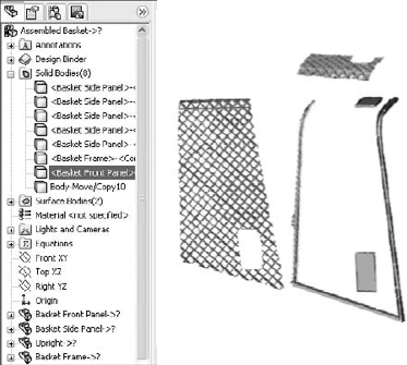
Figure 26.11. A complex model created as separate parts and brought together as bodies in a single part
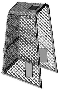
This part is molded using tooling pulls in five directions. Two of these directions are symmetrical, and the core block pulls in a single direction; as a result, in the end, the modeling has to account for three directions.
The rebuild time for a model like this can easily reach several minutes, and the feature count can be in the hundreds, or in this case, well over one thousand. To minimize the rebuild time, a different workflow was established for this part. First, the major inside and outside faces were created with surfaces. Next, the surfaces were saved into several other parts (using Master Model techniques that are discussed in Chapter 28). Each of these parts represents the part geometry that will pull in a particular direction from the mold. Enough information exists in the Master Model to align the features in each part.
The ribs on this part were created by making a single extrusion (the Rib feature could not be used because there was no geometry to serve as a boundary for the ribs), and then the extrusion was patterned and the pattern was mirrored. After all the ribs were created, they had to be shaped, and so the surfaces from the Master Model were used to cut the ribs to shape.
The ribs could not be extruded with a draft or with fillets because the outer and inner surfaces were non-planar. The draft had to be built as a Parting Line draft for the same reason, and the fillets had to be applied after the draft. Further, draft and fillets can only be applied to a single body at a time; as a result, a separate draft feature and a separate fillet feature had to be applied to each body, and each rib was a separate body. Once the draft and fillets were applied, the bodies were joined into a single body.
I recognize that this description of how I made the part is a lot to follow. The point is not to show in detail how the parts were built, but to demonstrate how you can get to a part with 1,200 features or more. It is precisely on parts with this level of complexity that you need to think about modeling the part in this modular fashion — build each part separately and bring each separate section of the part together as individual bodies.
Figure 26.11 shows two of the separate pull direction parts being separated from one another in the same way that the mouse part was shown exploded in the previous example. Here the frame is also modeled as a separate part, again because it was not so intimately related to the other parts and was easily separated out.
Once this was complete for each direction, the separate parts were put together as bodies into a single part and again joined together using the Combine feature. Having all those features in separate parts enables you to segment the rebuild time. This is the opposite of building all the parts of an assembly in a single part, where you are simply compounding your rebuild time. Figure 26.12 shows bodies joined together as a single body.
This is probably a technique that you will not use very often, but when you do, it can save you a lot of rebuild time. I use it whenever I have a model that takes more than 20 to 30 seconds to rebuild and I know that I am going to be working on it a lot; it must also lend itself to segmenting in the way that this one did, with easily definable areas.
Often when modeling, you "build what you know" and "fill in as you go." An example of this would be modeling a duct between end connections that are well defined. The duct in between is defined only by the ends, which must exist first. Another example is a connecting rod where you know the diameter of each end and the distance between the ends, and the connection between them is of secondary importance.
Figure 26.13 shows a connecting rod made in this way. In this case, the bearing seat at one end was created, and the other end was created by copying the body of the first one. From there, the link between bearing seats was created, which joined the separate bodies together into a single solid body.

This part contains some interesting features. First is the Thin Feature extrude that is used to make the first bearing seat, which is combined with a Mid-plane extrude to make it symmetrical at the same time. Then comes the Move/Copy Bodies feature, which copies the body in the same way that the feature in previous examples has moved bodies. Next is the use of the Extrude From option, which extrudes from a face, and then the use of the end condition Up To Next, which ends the feature neatly. The part also incorporates fillets that use faces and features to form the selection.
If you are not familiar with these options, I recommend that you open up the part from the CD-ROM and have a look at it. It is a simple part that takes advantage of nice but simple productivity-enhancing options that have been available for some time in the SolidWorks software. The part filename is Chapter 26 – Bridge.sldprt.
By default, Solid features have the Merge option selected, and they automatically combine with any bodies that they touch. At the same time, they do not display errors if the Merge option is selected but the new body does not touch any existing bodies.
Sometimes you must start a design before you know exactly how the product will be manufactured. This is an example of where the geometry of the finished product exists first and is then broken up into manufacturable parts. The initial model, shown in the image at the top in Figure 26.14, is created as a single part as a result of input from marketing, but when it comes time for manufacturing input, the part count and processes keep changing. Where the parts break from one another keeps changing as well. When that kind of change is happening, having the parts created as individual parts is a big liability because it is difficult to change. Changing which bodies are merged together is much easier.
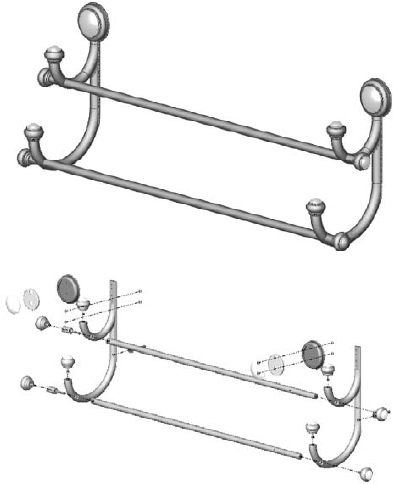
Figure 26.14. A towel rack, modeled as a single part and broken into individual parts in an assembly
It is worth mentioning two potential difficulties that you may run into with methods like this. The first is that if you have people making drawings from parts that have been derived from bodies in a single part, then they are forced into the Reference Dimension scheme of dimensioning parts because the feature dimensions do not survive being moved from the multi-body part. This may or may not be an issue, depending on how the people doing the drawings are accustomed to working.
The second potential issue is what you do in situations where there are multiple instances of a part that has been modeled this way. Notice in the towel rack in Figure 26.14 that there are several finials, spacers, rails, and other parts that are duplicated. This requires some manual assembly modeling. You can make the assembly directly from the multi-body part, but if you need to make multiple instances of particular parts, you need to do this manually rather than automatically.
In the first section in this chapter, I raised the questions of if or when multi-bodies should be used, and in the second section, I raised the question of why multi-bodies should be used. In this section, I simply ask, or rather answer, how they should be used.
The easiest way to create multiple bodies is to simply create what SolidWorks classifies as multiple disjoint closed contours. What that means is simply two circles or rectangles that do not touch or overlap. If these are created in the same sketch, then when extruded, they will create as many bodies as there are closed loops in the sketch.
If the part has an existing solid, then creating a sketch that does not touch the solid can also create a separate body. You cannot make Multiple Thin features in a single sketch. This is presumably because the interface has no way to identify different thickness directions for different open profiles. This holds true whether or not the Multiple Thin features create multiple bodies.
If a solid feature other than a mirror or pattern touches a solid body, then the new and the old bodies will be merged into a single body.
You can prevent a feature from automatically combining with other bodies by deselecting the Merge Result option. This holds true between features, but not across all bodies in a part. For example, if an extrude feature uses the Merge result option, all the bodies that it touches become merged together, but if the original extrude feature does not touch a body, it will not be merged. This option is shown in Figure 26.15 and is found on all features that create new solid bodies except for the Patterns, Rib, and Move/Copy Bodies features.

The Feature Scope used for multi-bodies is not the same as the Feature Scope used for assembly features, but it does function in a similar way. In assemblies, the Feature Scope identifies which parts are affected by the current assembly feature. In parts, it only applies to bodies and can be used for features that add material as well as features that remove material (assembly features can only remove material).
The Feature Scope is a way to make the Merge result option more selective. The Merge result option by default does not discriminate; it causes the feature to merge with any other solid body that it touches. However, the Feature Scope enables the user to select which bodies to merge with or otherwise affect. Feature Scope also applies to additional feature types such as cuts. The Feature Scope becomes available in the PropertyManager whenever there are multiple bodies in the part and an eligible feature is used. The Feature Scope panel is shown in Figure 26.16.
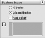
The default setting for the Feature Scope is to use the Selected bodies option with the Auto-select option. The All bodies option is essentially the same as using the Merge result option. When the Selected bodies option is selected and Auto-select is unselected, as is shown in Figure 26.16, you must select bodies for the current feature to affect them. New bodies that are added to the model are not automatically added to the list; you need to manually edit the feature and add additional bodies to the list as appropriate.
After you have selected the target body, deleting the new bodies that caused the problem in the first place, thankfully, does not make the problem reoccur. However, if the body that the rib is merged with is split using the Split feature, then that does cause a problem. As a result, the two things that cause the Rib feature problem are rolling back and either adding bodies or splitting the body to be ribbed.
Warning
As you encounter more specialized situations with multi-bodies and dependencies, you may notice more quirks in the SolidWorks internal body management. The next section on managing bodies addresses some of these quirks directly.
In cases like this, you can use the Delete Solid/Surface feature. This is alternatively called Delete Body, depending on where you look. Delete Solid/Surface removes the body from the body folder (discussed in the section on body folders). This is a history-based delete, which means that before the Delete Body feature in the tree, the body exists, and after the Delete Body feature in the tree, the body does not exist. This feature has no effect on file size, because the data for the body must still exist, and it has little, if any, effect on rebuild time. What is happening is that the body is still there; you just cannot see it and have no access to it.
Delete Solid/Surface is often used for other purposes as well, primarily to clean up a model at the end of the tree. The reasoning is that multiple bodies in a part confuse people. My recommendation here is to remove bodies if they are getting in the way, either for a hyper-sensitive feature like the Rib feature or if they are causing visualization problems.
Notice that the Bodies to Keep settings are also configurable; therefore, different bodies can be kept in different configurations, which is very useful.

To split a single solid body into multiple solid bodies using planes, sketches, or surface bodies
To save individual solid bodies out to individual part files
To reassemble individual part files that are saved out into an assembly where the parts are all positioned in the same relative position as their corresponding bodies
The last two functions of the Split feature are addressed in Chapter 28. The part of the Split feature that concerns this chapter is the first function mentioned, which is splitting a single solid body into multiple bodies using a sketch, a plane, or a surface body.
The Split feature cannot be used to split surface bodies. In fact, nothing in SolidWorks can split surface bodies. Only solid bodies can be split. Surface bodies can only be trimmed, so the effective workaround for not being able to split surface bodies is to copy the body, then trim and keep one side of the copy and the other side of the original. This seems like a functionality oversight, and would make a great enhancement request if you have ever come across the need for this functionality.
When you are using a sketch to split a single solid body into multiple bodies, the Split process works like this:
Create a sketch with an open or closed loop; even a mixture of open and closed profiles will work. If it is open, then the endpoints have to either be on an exterior edge or hanging off into space; they cannot actually be inside the boundaries of the solid.
Initiate the Split feature from the Features toolbar or from the menus by choosing Insert
Features Split. You can do this with the sketch active, with the sketch inactive but selected, or with nothing selected at all.
Click the Cut Part button. This does not actually cut anything; it only previews the split. When this is done, the resulting bodies appear in the window below and callout flags are placed on the part in the graphics window. These flags are often useless because they tend to point to the borders between two different bodies in such a way that it is completely ambiguous as to which body they are indicating. However, in the example shown in Figure 26.18, the result is very clear.

Check marks next to the body in the list indicate that the body will be split out. The lack of a check mark does not necessarily mean anything. For example, in Figure 26.18, notice that two boxes are checked, but this will result in a total of four bodies. If only Body 1 were selected, then the result would be only two bodies.
The callout flags and the bodies list where <None> is shown are looking for a path and filename to save the body out to a file. Again, this functionality is covered in Chapter 28 with the Master Model information.
Clicking the Save All Bodies button simply puts check marks in all the boxes. If the Resulting Bodies box contains more than ten bodies, then the interface changes slightly, as shown in the image to the right in Figure 26.18. The Consume cut bodies option removes, or consumes, any of the bodies that have a check mark.
Splitting with a plane provides the same type of results, and uses the same options, as splitting with a sketch. However, you never have to worry about the plane being extended far enough, because the cut is made from the infinite extension of the plane. The only thing you have to worry about with a plane is whether it intersects the part.
Surface bodies are used to split solid bodies for a couple of reasons. In the part shown in Figure 26.10, a surface body was used to make the split instead of a sketch or a plane, because both of those entities split everything in an infinite distance either normal to the sketch plane or in the selected plane. A surface body only splits to the extents of the splitting surface body. If you look closely at the part, you will notice that a plane or sketch would lop off one side of the sphere on top of the object, but the small planar surface is limited enough in size to only split what is necessary.
Another advantage to using a surface body is that it is not limited to a two-dimensional cut. The surface itself can be any type of surface, such as planar, extruded, revolved, lofted, or imported. Taking this a step further, the surface is not limited to being a single face, or a body resulting from a single feature; it could be made from several features that are put together as long as it is a single body and all the outer edges of the surface body are outside the solid body. If you examine the mouse part shown in Figure 26.1, you will notice that it has splits made from multi-feature surface bodies.
I mention splitting with surface bodies here because this is where I discuss the Split function, even though I haven't covered the surfacing functions yet. It may be useful to read parts of this book out of order; given how the topics interrelate, it is impossible to order them in such a way that some sections will not refer to a topic that has not yet been covered.
Cross-Reference
For more information about surface bodies, see Chapter 27.
Insert Part enables you to insert one part into another part. When inserting the part, you have the option to insert solid bodies, axes, planes, cosmetic threads, surface bodies, and several other types of entities, including sketches and features. The PropertyManager interface for the Insert Part feature is shown in Figure 26.19.

This feature has two major functions: inserting a body as the starting point for a new part, and inserting a body to be used as a tool to modify an existing part. Notice that the basket part shown in Figure 26.11 and Figure 26.12 also uses Insert Part to put together bodies to form a finished part.
When you use Insert Part, there is no Insert Part feature that becomes part of the tree. Instead, a part icon is shown with the name of the part being inserted as a feature.
Also notice in Figure 26.19 that the Launch move dialog option appears near the bottom, and is selected by default. This option launches the Move dialog box after you insert the part. This Move feature is the same as the Move/Copy Bodies feature, with the same options (translate or rotate by distance or angles, or use assembly-like mates to position bodies).
Insert Part is used in many situations, some of which are covered in Chapters 11 and 28 in the sections on skeleton techniques and Master Model.
One commonly used technique has to do with secondary operations. For example, you may have designed a casting that needs several machining operations after it comes from the foundry. The foundry needs a drawing to produce the raw casting, and the machine shop needs a different drawing to tap holes, spot face areas, trim flash, and so on.
You can use configurations to do this by using Insert Part is another way. This has nothing to do with multiple body techniques, but this is the only place where Insert Part is covered in much detail. One of the advantages of using Insert Part is that you no longer carry around the overhead of all the features in the parent part. It is as if the inserted part were imported. The configurations method forces you to carry around much more feature overhead. Of course, the downside is that now there is an additional file to manage, but this can be an advantage because many companies assign different part numbers to parts before and after secondary operations.
Looking back to the mouse shown in Figure 26.1, the main part has been split into several bodies. You can use Insert Part to insert the whole mouse into a new part where all the bodies except one are deleted, and then the remaining body serves as the starting point for a new part. Many additional features are needed on all the bodies that make up the mouse, such as assembly features, cosmetic features, functional features, and manufacturing features.
Managing bodies in SolidWorks is not as clean a task as managing parts in an assembly. As you work with bodies, you may discover some surprises in how bodies are managed. This section prepares you for the challenges involved in managing bodies in SolidWorks.
The top of the FeatureManager includes a pair of folders: one called Solid Bodies and the other called Surface Bodies. These folders are only there if you have solids or surfaces in the model, and they reflect the state of the model at the current position of the Rollback bar. As a result, the folders can change and even disappear as you roll the tree back and forth in history. Figure 26.20 shows the top of a FeatureManager that has both solid and surface body folders. Notice that the number in parentheses after the name of the folder shows how many bodies are in that particular folder.
An odd fact about these folders is that you are allowed to rename the folders, but the name changes never remain. If you go back to rename the folder again, the name that you previously assigned will display.

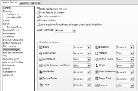
You may encounter another problem with the display of FeatureManager header items in general when they are set to Automatic display (display only when they contain something). This does not guarantee that the folder is going to display when it should. A more direct way of saying this is that the Automatic setting works incorrectly from time to time. For this reason, I suggest using the Show option to display important folders. Figure 26.21 shows the Options page (Tools
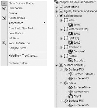
By right-clicking either of the bodies folders, you can select the Show Feature History option, which shows the features that have combined to create the bodies in an indented list under the body name. This view of the FeatureManager is shown in Figure 26.22. This option is very useful when you are editing or troubleshooting bodies.
Figure 26.22 also shows the other options in the right mouse button (RMB) menu. All the bodies in the folder can be alternately shown or hidden from this menu, as well as deleted. While the Hide or Show state of a body does not create a history-based feature in the tree, the Delete feature does, as discussed previously. The Insert into New Part feature and the Save Bodies feature shown in this menu are discussed in Chapter 28.
You can expand the Display pane in parts to show display information for bodies. In Figure 26.23, the Display pane shows the colors assigned to the solid bodies, as well as the fact that several surface bodies exist but are hidden.

The folders also make bodies easier to identify, especially when combined with the setting found at Tools
You can hide or show bodies in one of several ways. I have already described the method of using the bodies folders to hide or show all the bodies at once, but you can also right-click individual bodies in the folders to hide or show them using the RMB menu. Remember that with the context bars, you have the option to use them with the RMB menu as well as with left-click selections. I include all context bar options in the RMB menu generically.
If you can see a body in the graphics area, then you can right-click the body and select Hide under the Body heading. This works for both solids and surfaces. The Display Pane, shown to the right of the FeatureManager in Figure 26.23, can also be used to hide or show bodies, change body transparency and appearance, as well as change the display mode of bodies. Display Pane is a handy tool for visualization options.
When you are hiding or showing bodies from the FeatureManager, but not using the bodies folders and using the features themselves instead, things get a little complicated. If you want to hide or show a solid body, then you can use any feature that is a parent of the body to hide or show the body. For example, you can use the Shell feature in the mouse model to hide or show all the bodies of which it is a parent.
Other facts that you need to know about bodies and their hide or show states are that the Hide or Show feature is both configurable and dependent on the rollback state. As a result, if you hide a body, and then roll back, it may appear again and you will have to hide it. Then, if you roll forward, the state changes again. Also, a body can be hidden in one configuration, and then when you switch configurations, it remains hidden. This makes it rather frustrating to work with bodies. To me, it would be nice if bodies had simple on/off switches.
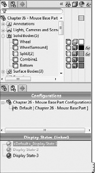
SolidWorks 2010 adds the Display State functionality from assemblies to multi-body parts. This is extremely handy, and a very fast way to change color, transparency, or display modes for individual bodies. The best way to handle this is to expand the Display Pane and control Hide/Show, Display Mode, Appearance, and Transparency directly from the Display Pane. Figure 26.24 shows the Display Pane in action on a multi-body part.
In Figure 26.24, the FeatureManager panel is split so you can see the configurations and Display State information alongside the bodies folder and display pane. If you are familiar with Display States in assemblies, it is the same as for bodies.
Another change in SolidWorks 2010 that is related to the Display States, and in particular the Appearances, is that you are now able to assign different materials to each body. I'm not a big fan of this change because I think it starts to encroach too much on the realm of the assembly. If different parts are made of different materials, the only situations in which I would model this way would be overmolds, where multiple materials are molded onto one another, and inseparable subassemblies, like purchased components such as screws with captive washers or a circuit board with rivets. If you need to manufacture something that has different materials, you need to have each material in a separate file for manufacturing purposes. Computer Numerical Control (CNC) software operators generally do not want parts that need to be machined separately given to them as multi-body single parts. To apply materials to bodies, right-click the body in the Solid Bodies folder and select Material.
Warning
Some features exclude bodies if the bodies are hidden when you edit the feature. Be careful of this, and be sure to show all the bodies that are used in a particular function before you edit it. For example, if a body is hidden and you create a new extrude that touches the hidden body, then the new body does not merge with the hidden one even if the Merge option is on. If the hidden body is then shown and you edit the second body, then the bodies will merge upon the closing of the second body.
Delete Solid/Surface does not affect file size or rebuild speed. In fact, I find it difficult to come up with examples of when you should use it, other than the situation already mentioned with the Rib feature, or if a throwaway body somehow remains in the part. Some people use this feature to clean up the organization of the tree, which could be useful if there are many bodies in the part. Other users insist on keeping the tree free of extraneous bodies and immediately delete bodies that have been used. To me, this technique replaces one kind of clutter with another, and means that tools that should be available to you (solid or surface bodies) are not available unless you reorder the Delete Body feature down the tree and/or roll back. In any case, this is really a matter of personal working style and not of any great importance.
Notice that the bodies that you see in the folders have been named for the last feature that touched a given body. That naming scheme is as good as any, except that it means that the body keeps changing names. If you deliberately rename a body, it will retain the name through future changes. You should follow the same rules of thumb for naming bodies as you do for naming features. It is not necessary to rename every body, but if you will use one body frequently and need to select it from the FeatureManager, renaming it is very useful.
Various types of special SolidWorks documents require that you work with multi-body data. Those are sheet metal, weldments, and molds. Sheet metal and Weldments are SolidWorks files with special properties, and the molds are simply created from a separate set of specialized Mold Tools.
Weldments are a special type of SolidWorks document that require the use of multiple bodies. The Weldment tools are covered in detail in Chapter 31, but I mention them here because they fall under the topic of multiple bodies. Each structural member in a weldment frame is created as a separate solid body. So if you are getting involved in using the Weldment tools in SolidWorks, you will need to also master the multi-body tools.
New in SolidWorks 2010 is the capability to have multiple bodies in sheet metal parts, and put sheet metal parts into weldments. Sheet metal components are frequently used in welded frames, so SolidWorks added the multi-body functionality to sheet metal. Sheet metal is covered in Chapter 29, and the details of multi-body modeling as it relates to sheet metal are covered there. Again, I include the multi-body capabilities of sheet metal in this chapter as an introduction to the idea.
Creating mold geometry using SolidWorks Mold Tools is another multi-body function. Other mold creation software that works within SolidWorks uses assemblies to do this, but SolidWorks has chosen to use bodies. You can also do the same kind of work without using the specialized tools if you choose, and can even work exclusively in solids or in a hybrid solid and surface workflow. Unless you choose to create geometry for various types of molding or casting manufacturing methods using assemblies, you are probably going to need to do it using multi-body parts. SolidWorks Mold Tools are discussed briefly in Chapter 32.
This tutorial contains various short examples of multi-body techniques in order from easy to more difficult.
This tutorial gives you some experience using the Merge Result option and using features on individual bodies to demonstrate the local operations functionality of multi-body modeling. Try these steps:
Start a new part, and sketch a rectangle centered on the origin on the Top plane. Size is not important for this exercise.
Extrude the rectangle to roughly one-third of its smaller dimension.
Open a second sketch on the Top plane. Hide the first solid body by right-clicking it in either the FeatureManager or the graphics window.
Show the sketch for the first feature, and draw a second rectangle on the far side of the rectangle from the Origin. Make sure that the second rectangle gets two coincident relations to the first sketch at two corners so that the rectangles are the same width. When the sketch is complete, hide the sketch that was shown.
Extrude the second rectangle to about two-thirds of the depth of the first rectangle.
Note
Notice that the Merge option was not changed from the default setting (On) for the second extrude, but because the first extrude was hidden, the second extrude did not merge with it. Be careful of subsequent edits to either of the features if the first body is shown, because this may cause the bodies to merge unexpectedly. In this tutorial, the bodies are later merged intentionally. Ideally, what you should do is deselect the Merge option of the second extrude.
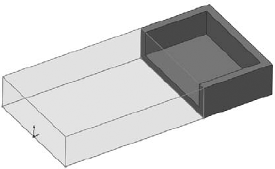
Shell out the second extrusion by removing two adjacent sides, as shown in Figure 26.25. One of the sides is the top and the other is the shared side with the hidden body. The body that should be hidden at this point is shown as transparent in the image for reference only. The body was made transparent to make it easier to select the face of the second body.
Show the first body either from the Solid Bodies folder at the top of the tree or from the RMB menu of the first solid feature in the tree.
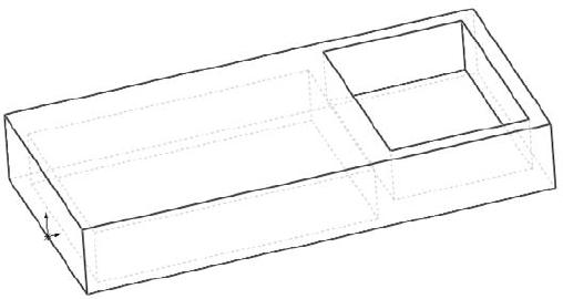
Shell the bottom side of the first body, so that the cavities in the two bodies are on opposite sides.
Combine the two bodies using the Combine tool you can find by choosing Insert
FeaturesCombine. This feature is also available via the RMB menu in the solid body folder. Select the Add option and select the two bodies. Click OK to finish the feature. Figure 26.26 shows the finished part.
This tutorial guides you through the steps to delete a pattern of features from an imported body, separate one of the features, and then pattern it with a different number of features. This introduces some simple surface functions in preparation for Chapter 27. Follow these steps:
Open the Parasolid file from the CD-ROM called Chapter 26 –
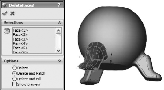
Bonita Tutorial.x_t.Using the Selection Filter set to filter Face selection (the default hotkey for this is X), select all the faces of the leg. You can use window selection techniques to avoid clicking each face.
Click the Delete Face button on the Surfaces toolbar, or access the command by choosing Insert
FaceDelete from the menus. Make sure that the Delete and Patch option is selected. The selected faces and the Delete Face PropertyManager should look like Figure 26.27. Click OK to accept the feature.Repeat the process for a second leg, leaving the third leg to be separated from the rest of the part and patterned.
After the two legs have been removed, click the outer main spherical surface, and then choose Insert
SurfaceOffset from the menus. Set the offset distance to zero. Notice that a Surface Bodies folder is now added to the tree, near the top.
Hide the solid body. You can do this from the Solid Bodies folder, from the FeatureManager, or from the graphics window.
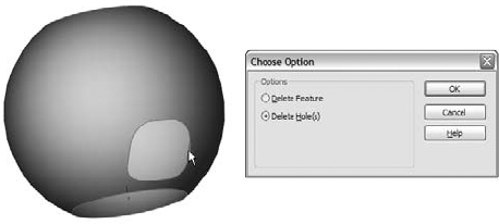
Hiding the solid leaves the offset surface, and there should be three holes in it. Select one of the edges of the hole indicated in Figure 26.28 and press the Delete key. The Choose Option dialog box appears. Select the Delete Hole option rather than the Delete Feature option. The Delete Hole operation becomes a history-based feature in the model tree. Before moving on to the next step, remember that you may need to turn off the Selection Filter for faces.
Note
Delete Hole is really a surface feature called Untrim. Untrim is discussed more in Chapter 27, but you can use it to restore original boundaries to a surface.
Once you delete the hole from the surface body, change the color of the surface body the same way you changed the colors of parts, faces, and features.
Click the surface body in the Surface Bodies folder and either press the Delete key, or select Delete Body from the RMB menu. Then click OK to accept the feature. This places a Delete Body feature in the tree. It keeps the body from getting in the way when it is not needed. This is not a necessary step, but many people choose to use it. (Suppress the Delete Body feature, since this body is needed again later.)
Tip
If you delete a body in this way and then need it later down the tree, you can delete, suppress, or reorder the Delete Body feature later in the tree.
Now show the solid body. You will notice the color of the surface conflicting with the color of the solid. This mottled appearance is due to the small approximations made by the rendering and display algorithms.
Initiate the Split feature by choosing Insert
FeaturesSplit from the menus, or clicking the Features toolbar. Use the surface body to split the solid body. Click the Cut Part button, and select the check boxes in front of both bodies in the list. Click OK to accept the feature. Notice now that the Solid Bodies folder indicates that there are two solid bodies.From the View menu, select the display of Temporary Axes. Initiate a Circular Pattern feature, selecting the temporary axis as the axis, and the split-off leg in the Bodies to Pattern selection box. Set it to four instances, as shown in Figure 26.29.
Use the Combine feature to add together all five bodies. You can access this feature by choosing Insert

Beginning to understand how to work with multiple bodies in SolidWorks opens a gateway to a new world of modeling possibilities. Like in-context design, multi-body modeling is definitely something that you have to go into with your eyes open. You will experience difficulties when using this technique, but you will also find new possibilities that were not available with other techniques. The key to success with multi-body techniques is understanding the capabilities and limitations of the tools.
When using a model with the multi-body approach, make sure that you can identify a reason for doing it this way rather than using a more conventional approach. Also keep in mind the list of applications or uses for multi-body modeling mentioned in this chapter. For some types of work, you cannot avoid multi-body modeling, such as using the SolidWorks Mold Tools and Weldments.