
SolidWorks has several tools that are specific to modeling and evaluating plastic parts. These tools can help simplify and standardize some of the complex repetitive tasks involved with plastic part design. Another set of task-specific tools exist for automating mold cavity/core modeling tasks. So whether you are a plastic part designer or an injection mold designer, SolidWorks offers tools tailored to your needs.
You can manually do all the work that these tools automate, and sometimes you need to be able to do the work manually when the automated tools do not provide the needed options or flexibility.
Because of the specific needs of plastic part modeling and mold design, SolidWorks has a set of powerful evaluation tools that help you query your models to check the amount of draft, thickness, and location of undercuts. Finding design-related manufacturability problems in manufacturing is expensive. Finding them in the design office is far less expensive and conserves time. A good grasp of the evaluation tools is an important component of good plastic part and mold modeling practice.
This chapter is written for the user who is already experienced in plastics practice and terminology, but needs to understand the SolidWorks tools used with the plastic and mold features. In this chapter, I assume that the reader already has a grasp of basic plastics and mold design.
The plastic features available in SolidWorks are the Mounting Boss, Snap Hook, Snap Groove, Vent, and Lip/Groove. These features offer standardized but flexible geometry to help you make more consistent models more quickly, and with less tiresome repetition. In this chapter I also consider the various functions of the Draft feature in SolidWorks. Other features such as Shell and Indent are frequently used in plastic parts, but I cover them in Chapter 7. You can find all the features in this section on the Fastening Features toolbar.
Some of these features have applications beyond just injection molded plastic parts. Many molding, casting, or "net shape" processes exist in plastic materials, as well as metals, ceramics, and composites.
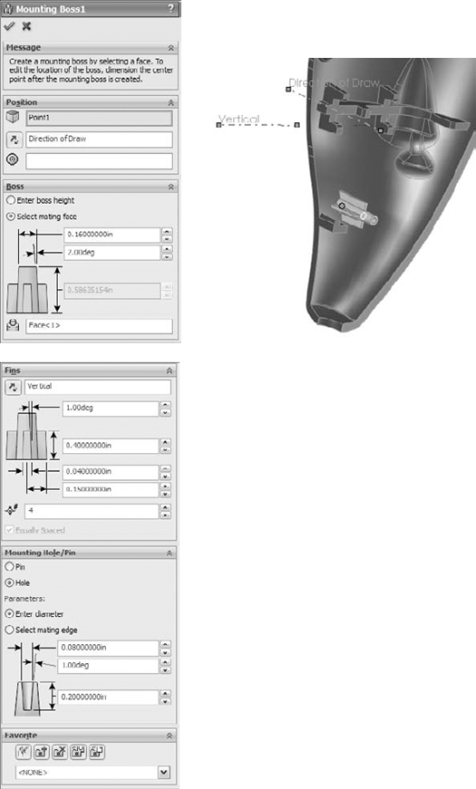
Figure 32.1 shows the Mounting Boss PropertyManager along with the preview of the boss in progress. The part used in this figure is on the CD-ROM in the data for Chapter 32, and is called Chapter 32 – right frame.sldprt.
The workflow for the Mounting Boss feature is as follows:
Select a spot on the part that represents where the boss will attach to the part. This can be either a flat or curved face. In the example in Figure 32.1, because I selected a curved face, it is necessary to also supply a direction of pull. If you select a flat face, the direction selection box in the next step is not available.
Select a plane, planar face, edge, or axis to establish the axis of the boss. This is usually the direction of draw. Notice in the part shown in Figure 32.1 that an axis established early in the part is named as the Direction of Draw. In early 2009 releases, the Change Direction arrows do nothing. This step is optional. The default is the direction normal to the face selected in Step 1.
Select an existing circular edge to align the boss. The new boss will be concentric with the circular edge. This step is also optional. You can choose to use dimensions to locate the boss after the feature is created. If you use dimensions, you cannot locate the boss while the PropertyManager is active.
The Boss panel of the Mounting Boss PropertyManager is used to establish the height and other dimensions of the central boss. Diameter and draft dimensions are obvious. You can establish height by a dimension or by an "up to" face using the Select mating face option. There is no option for an "offset from face" end condition.
The Fins panel of the Mounting Boss PropertyManager is used to control the alignment, draft, height, width, and patterning of the ribs around the boss. The first box is for a direction vector such as a plane, edge, or axis to establish the rotational orientation of the ribs. You cannot use a sketch for this. The significance of the dimensional values is obvious. The fin pattern function is also obvious except for the Equally Spaced option, which is only available when the number selected is 2. Then you must select a vector to establish the orientation of the fins, which form a right angle for a corner.
The Mounting Hole/Pin panel enables you to specify a pin or hole boss and the associated sizes. It is interesting to me that it doesn't enable through holes or counterbore holes from the outside of the part, along with associated screw sizes for clearance.
SolidWorks has renamed Favorites in the rest of the software to Styles, but in the Mounting Boss and the Lip/Groove, it is still called Favorites, and saves settings like other Favorites/Styles functionality.
After you have successfully accepted the creation of the boss, if you did not use a circular edge to locate the boss (Step 3), you can expand the Mounting Boss feature in the FeatureManager and edit the 3D sketch under the boss. Inside this sketch is a point, which you can dimension to locate precisely. Remember that dimensions in 3D sketches follow some special rules. To get orthogonal dimensions parallel to X, Y, or Z axes, you will need to dimension from planes. 3D sketch dimensions do not snap to horizontal or vertical orientations like 2D sketches.
If you have selected a flat face for the initial position of the boss, you get a 2D sketch instead of a 3D sketch.
The features created by this tool are not manually editable. They are not made of extrudes and rib features that are accessible behind the Mounting Boss interface. You have to go through the Mounting Boss PropertyManager to edit the features, and cannot edit sketches used to make the features.
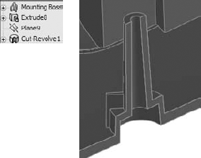
SolidWorks designed this feature primarily as a way to create pin-and-hole press pin bosses. These are certainly needed, but also needed are screw bosses. You will have to size your own screw holes either for threaded inserts or for thread cutting screws. You will also need to manually create some of your own features if you want to make a counterbored clearance hole for a screw, as shown in the cross section in Figure 32.2.
An effective way to pattern a single Mounting Boss feature around a part is to use the Sketch Driven Pattern. This feature uses a sketch with a set of points where each point represents the center of a patterned instance. Refer to the model on the CD-ROM and examine the sketch driven pattern at the bottom of the FeatureManager. Use the Chapter 32 – right frame.sldprt file, and change to the "nonmirror" configuration if it is not already there.
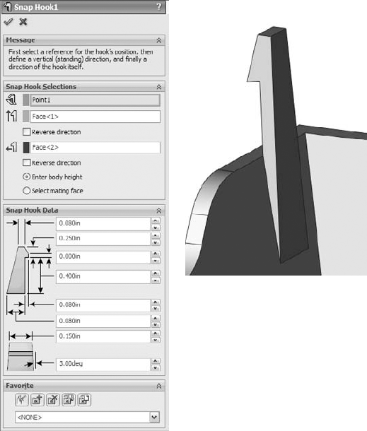
The workflow for the Snap Hook feature goes like this:
Select a spot on the model that will correspond to the center of the undercut edge where the hook intersects the part. It looks like you can select a face or an edge when you first create the feature, but the software always converts the selection to a point when the feature is accepted.
Select a vector (face, edge, axis, not a sketch) to set the vertical orientation of the hook, or the "top."
Select another vector to define the "front" of the hook (the undercut side).
Choose to select a mating face or enter a number to define the height of the hook.
This feature uses a 3D sketch point where you made the selection in Step 1. You cannot dimension this point while setting up the feature, only by creating the feature and then going back and editing the 3D sketch absorbed under the feature. This is also the arrangement with the Lip/Groove. Remember that you cannot dimension 3D sketches the same way that you dimension 2D sketches. You may need to dimension to planes rather than edges or points to get the dimensions you really intend.
The Snap Groove PropertyManager interface is shown in Figure 32.4, along with a cross section of a finished Snap Hook and a Snap Hook Groove. To use the Snap Hook Groove feature, you must have already created a Snap Hook feature. The interface seems to imply that it requires the body the groove goes into to be in the same part as the body of the hook feature, but this is not the case. You can create this feature in-context between a part with a hook and the part to receive the groove.
Note
Before designing extensive undercuts into a plastic part, it is advisable to talk to the mold builder if possible. They may have either limited or special capabilities that could impact on the practicality of one approach as opposed to another. I find it is frequently beneficial to work closely with a mold designer or builder on plastic part projects.
When I model plastic parts, rarely do situations call for a generic snap feature. Usually situations require more inventiveness due to space restrictions or curvature or material thickness considerations. The Snap Hook and Snap Hook Groove features are reasonably easy to use, but may not have the flexibility for application in all situations.

The workflow for this feature goes like this:
Select the part or body to receive the groove.
Select the part or body to receive the lip.
Select a plane, planar face, straight edge, or axis to establish the direction of pull.
Select faces that represent the parting surface along the area to get the lip/groove.
Select edges that the lip/groove will affect.
Set dimensions for both lip and groove features.
When the Lip/Groove feature works correctly, it saves a lot of time. The work-around techniques are time-consuming and potentially error prone. SolidWorks has put some additional development time into Lip/Groove, so if you have used it before and found it lacking, you might try it again. The 2010 version removes some of the limitations, particularly those involving ribs intersecting the main wall and multiple sections of wall needing lip or groove features.

In some cases, the automated tools may not be able to create what you need to create. You can employ one of several manual workarounds to make lips and grooves. Several techniques exist.
On a planar parting line, you can use sketches offset from the edges and then extrude either a boss or a cut.
Using a thin feature extrude (boss or cut) can also be effective on planar parting lines.
Using trimmed and thickened (again, boss or cut) surfaces can be effective but may also be more difficult.
One of my favorite methods, especially for non-planar parting lines, is to combine a thin feature with an extrude up to an offset surface body.
Using a sweep to cut or add material can be effective on either planar or non-planar parting lines.
Each of these is really a work-around technique and not a specific plastic modeling tool, I will not go into depth on these techniques here. On the CD-ROM, you will find example parts that demonstrate each technique.
To me these names are not very descriptive. I call the two orientations plan view (view from the top, looking in the direction of draw, normal to the sketch plane) and skyline (looking from the side, perpendicular to the direction of draw, rib is parallel to the sketch plane). To me, these names are more intuitively descriptive.
Ribs can incorporate draft, extend, or trim the feature beyond the sketch automatically, and break normal sketch rules (plan view ribs only).
Ribs do have some limitations or opportunities for improvement, which I will discuss briefly later in this section. It is as important to understand what features can't do as it is to understand what they can do.
Figure 32.6 shows a plan view rib that violates normal sketch rules. Also shown is the Rib PropertyManager. Several models on the CD-ROM show examples of various rib techniques.
The Rib feature workflow should be self-explanatory:
Draw the sketch, either the plan view or skyline. The sketch represents the top of the Rib. Material can only be added between the sketch and the rest of the part.
Initiate the feature, and set the type of rib and the direction. Use the Flip Material Side toggle to change the direction of the gray arrow, which should point from the top of the rib toward the part.
Set the thickness and draft amount and direction.
When you create ribs, you almost always apply draft to them. You can apply draft as a separate feature, or you can apply draft as a part of the Rib feature. It is often easier to just do it as part of the Rib feature, but some people like to make all their drafts as separate Draft features to keep the part faces orthogonal for as long as possible, or they just like to organize all the Draft features into a folder at the end of the FeatureManager so that there is never any question about which feature controls the draft.
By default, when you apply draft as a part of the Rib feature, the draft is applied from the sketch end of the rib. This can cause rib thickness problems if you have created a skyline rib where the rib may have various heights. In this case, the top of the rib will vary in thickness, and it may cause the base of the rib to be too thick. When you work this way, sometimes you have to experiment with the proper thickness at the top of the rib in order to get a thickness at the bottom of the rib that will not cause sink marks on the outside face of the part.

A solution to this is to control the thickness of the rib at the base, and then draft away from that. This process is more in line with standard plastics processes anyway, which generally give dimensions at maximum material condition, and then the draft always removes material. Thinking of draft as always removing material helps plastic part modelers and mold designers to remain "steel safe." It is always easier to remove steel from a mold (which adds material to the plastic) than it is to add steel to the mold.
Starting in the SolidWorks 2009 release, you can now specify the thickness and draft such that the base of the rib maintains a specified thickness, and the draft is applied from the base of the rib. The option to do this does not appear until you turn on the draft for the feature.
The Rib feature is sensitive to changes in the number of solid bodies in the part. For example, if you build a part and put a Rib feature in it and it only has one body, then roll back before the rib and do something that makes two bodies when you unroll the FeatureManager, the Rib feature will fail. The way to fix this error is to edit the rib and use the Feature Scope at the bottom of the PropertyManager to select which body the rib is meant to intersect. The Feature Scope box does not appear unless the part has multiple bodies.
The Intersection Curve is on the Sketch toolbar. While in a 2D sketch, activate the tool, and then select faces that intersect the current sketch plane. Deactivate the tool when you are done. You may want to select all the lines selected by the Intersection Curve tool and turn them into construction geometry. This provides a good reference for the rib sketch.
Figure 32.7 shows an example of using an Intersection Curve as a reference for setting up a rib sketch. The construction lines at the ends and below the right end of the skyline rib sketch are Intersection Curves.

At the ends of the shell, the intersection curves serve to give the sketch a reference point to be fully defined. Under the right end of the rib sketch, the intersection curve gives you a reference to dimension the height of the rib in the shallower section of the part. The part shown in Figure 32.7 is on the CD-ROM as Chapter 32 – skyline.sldprt.
The Rib feature automatically extends and trims ribs based on your rib sketch. This is a great ease-of-use function, but it tends to lead to sloppy sketching for Rib features. If you sketch a rib, and the sketch does not lead all the way to the wall of the part, SolidWorks extends it. If your sketch line goes past the wall, SolidWorks trims the rib so that it only goes up to the wall of the part. Figure 32.8 shows how the two straight ribs are extended from the existing sketches on a pair of plan view ribs.
Sometimes you do not want a rib extended to the wall of the part. You may want to terminate a rib at a specific location in the middle of the part. The way to do this is to use a skyline rib and end the skyline sketch with a vertical (plus or minus draft) line that points to the base of the part. Figure 32.9 shows how to accomplish this. Notice that on the left end of the rib, it is extended straight down to the bottom of the part, and on the right side of the rib, it is extended up to the next wall.

A final termination situation I want to mention is one that can sometimes happen at curved edges. If the extension of the rib cannot be contained by the model, the rib will fail. This is not always as obvious a situation as you might think. When a non-horizontal rib intersects a curved edge, it usually forces you to fake something a little. Figure 32.10 shows an example of why this is.
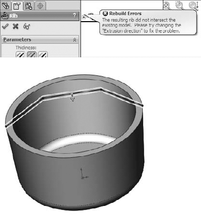
The reason for the error shown in Figure 32.10 is that even though the rib sketch intersects the edge of the part, the width of the top of the rib would go past the edge and not intersect anything. One way to deal with this is to make the sketch intersect the part a little closer to the center of the part from the edge. Another way would be to put a short vertical line at the end of the rib.
Thin feature extrusions are sometimes used in place of ribs. Thin features do not have all the specialized options available with the Rib feature, but they do offer simplicity as the main attraction. Thin features can substitute for Rib features when the rib is a stand-alone rib that doesn't touch the side walls of the part. They can be used to sketch and extrude from the bottom of the rib or from the top. When extruding a thin feature with draft, the end faces get drafted as well, which might cause a problem if you are trying to attach the rib to a wall. Extruding a thin feature down from the top of the rib can replace a plan view rib, but it will not enable you to break those pesky sketch rules that the Rib feature simply dispenses with.
I personally prefer to use Rib features, except for free standing ribs where you do not want the sides extended up to the next wall.
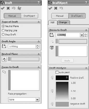
Figure 32.11 shows the PropertyManager of the draft feature, including the DraftXpert, which is mentioned later in this section.
The workflow for Neutral Plane draft is as follows:
Select Neutral Plane — plane or planar face at which the intersection of the drafted face does not move. The direction of pull is always normal to the Neutral Plane.
Set the draft angle — how many degrees from the direction of pull vector selected faces should be tilted. This is not a cumulative angle, so applying 3 degrees of draft to a face that is already drafted 5 degrees results in 3 degrees rather than 8 degrees.
Select the Direction — one side or the other side of the Neutral Plane. The arrow points in the direction of decreasing material. If you are drafting a surface body, the "decreasing material" concept does not apply, so you just have to experiment to see which direction is the one you intend. The Draft feature does not have a preview option.
Select faces to draft — use face propagation options. Inner/Outer faces refer to inside or outside loops around the Neutral Plane face. All means all faces that have an edge on the Neutral Plane face.
The workflow for Parting Line draft is as follows:
Select a direction of pull — this can be an edge, axis, sketch line, plane, or planar face. You also have to set the direction to positive or negative along the selected direction.
Select the parting lines — these are edges of the faces you want to draft. The parting line edges remain stationary while the rest of the face tilts. Along with the parting line selection, you may also need to use the Other Face option. Every edge is adjacent to two different faces. The Draft feature automatically selects the face it thinks you want to draft, but it does not always get it right. Other Face enables you to intervene when the automatic selection is incorrect.
Set the draft angle — remember that you can use the Allow Reduced Angle option if you need to.
The most complex of the types of draft that SolidWorks creates is the Step draft. Step draft is used on non-planar parting lines when Parting Line draft would cause the drafted faces to be split into multiple faces.
The word "step" can be said to refer to two different aspects of this feature. First, the parting line can said to be a "stepped" parting line because it is non-planar and at two different levels. Second, the draft actually steps out the drafted face at one level of the parting line. Step draft keeps the face intact and introduces an intentional mismatch ledge (step) at the parting line.
Figure 32.12 shows the difference between Parting Line draft and Step draft on a simplified part. The image on the left is the Parting Line draft. The middle image is Step draft where a ledge is only created on one side of the parting line. The image to the right is essentially double Step draft, where the total step size is minimized by distributing it across both sides of the stepped parting line.

The draft in these images is slightly exaggerated to make it easier to see.
The workflow for Step draft is as follows:
Start with a part that has a stepped split line, where the angled line makes angles of more than 90 degrees rather than less than 90 degrees.
Create a plane that defines the direction of pull and is located at the level of one of the split lines (for single step draft) or at the midpoint of the angled line (for double step draft). The location of the plane will determine the "pivot" point for the drafted faces. Essentially the line of intersection between this plane and the drafted face will remain stationary and the rest of face will pivot around it.
Initiate the Draft feature, and set the option to Step draft. Consult your tooling people about whether to use tapered or perpendicular steps. Perpendicular are probably easiest to tool.
Select the edges of the parting line. Make sure that the yellow arrows indicate which faces you want to apply draft to.
The draft for the other face can be accomplished in a number of ways, but it does not require another Step draft feature. You can use a Neutral Plane feature, using the plane created in Step 2 as the Neutral Plane. It will maintain the steps created by the Step draft feature.
SolidWorks draft is powerful, but it is not omnipotent. There are things it cannot do. The main limitation of draft in SolidWorks that irritates me is that it cannot draft faces in both directions in the same feature. For example, if you have a parting line on a part, you must first draft the faces on one side of the parting line, then the faces on the other side of the parting line. This results in two separate features rather than a single feature. Is this a serious limitation? No, it is simply an inconvenience.
Further, you can only draft faces from a single body at a time. Again, this is an understandable limitation, but there are times when it is annoying and inconvenient.
However, its biggest limitation is that you can't draft a face if it has a fillet on one of its edges that runs perpendicular to the direction of pull. To get around this, you usually have to tinker with the feature order. On imported parts you might have to use FeatureWorks to remove the fillet or Delete Face to re-introduce the sharp corner.
Draft is certainly one of those functions that require you to understand a little bit about the actual capabilities of CAD. Part of the key to success with the Draft feature is that you have your expectations aligned with the actual capabilities of the software. If you recognize a situation where the draft can not work, you may be able to correct the situation by changing feature order, combining draft features into a single feature, breaking the draft into multiple features, or changing the geometry to be more "draft friendly."
Sometimes the Allow Reduced Angle option can be used for Parting Line draft. If you use this, follow it up with a draft analysis to make sure that you have sufficient draft in all areas of the model. This option enables the software to cheat somewhat in order to make the draft feature work. The SolidWorks Help documentation actually has a more detailed explanation of when to use this option. I tend to just select it if a draft fails, particularly if the parting line used becomes parallel or nearly parallel to the direction of pull.
Draft can fail for a number of reasons, including tangent faces, small sliver faces, complex adjacent faces that cannot be extended, or faces with geometry errors. When modeling, it is best to minimize the number of breaks between faces. This is especially true if the faces will be drafted later. Generally, the faces you apply draft to are either flat faces or faces with single direction curvature. You can't just expect SolidWorks to draft any old junk you throw at it; you have to at least give it a fighting chance by making good clean geometry.
When draft does fail for a reason that doesn't seem obvious to you, you should use the Check utility under the Tools menu and also try a forced rebuild (Ctrl+Q) with Verification on Rebuild turned on.
The plastic evaluation tools in SolidWorks enable you to automatically check the model for manufacturability issues such as draft, undercuts, thickness, and curvature. The tools used to do this are the Draft Analysis, Thickness Analysis, Undercut Checker, and Curvature tools.
Basic
Gradual Transition
Face Classification
Find Steep Faces
Draft Analysis is found in the View
The Basic draft analysis (with no options selected) simply colors faces red, green, or yellow. Colors may display transitioning if the draft shifts between two classifications. This transition type is shown in Figure 32.13 in the image to the right. For a clearer view of this method, look at the Chapter 32 Draft Analysis.sldprt part on the CD-ROM.
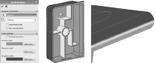
You can perform all types of draft analysis in SolidWorks by selecting a reference flat face or plane, and setting a minimum allowable angle. In Figure 32.13, all walls have at least a one-degree draft, except for the rounded edge shown in the image to the right and the dome. Both of these shapes transition from an angle less than one degree to an angle greater than one degree.
This basic analysis is good for visualizing changes in draft angle, but it also has some less desirable properties, which will become apparent as you study the other types of draft.
Although the Basic draft analysis is able to show a transitioning draft, the Gradual Transition draft analysis takes it a step further. With the Gradual Transition, you can specify the colors. It is also useful because it can distinguish drafts of different amounts by color. It may be difficult to tell in the grayscale image in Figure 32.14, but the ribs, which were created at one degree, have a slightly different color than the floor of the part, and the walls also have a different color. Notice that cavity and core directions have different colors, as well. You may want to open this part in SolidWorks, re-create the settings, and run the analysis so that you can see the actual colors.

Some problems arise when you use this display mode, the first being the flat, non-OpenGL face shading that is used to achieve the transitioning colors. This often makes it difficult to distinguish curved faces, and faces that face different directions. The second problem is that you cannot tell that the boss on top of the dome has absolutely no draft. In fact, there is no way to distinguish between faces that lean slightly toward the cavity and faces that lean slightly toward the core. The third problem is the strange effect that appears on the filleted corners. The corners were filleted after you applied the draft and before the shell, and so the filleted corners should have exactly the same draft as the sides; however, from the color plot, it looks to be a few degrees more.
Warning
Software can sometimes interpret things differently from the way that a person does. As a result, any computer analysis must be interpreted with common sense.
Due to this and some of the other problems that I mentioned earlier, I recommend using the Gradual Transition draft analysis in conjunction with one of the other tests. Gradual Transition gives an interesting effect, but it is not a reliable tool for determining on its own whether or not a part can be manufactured.
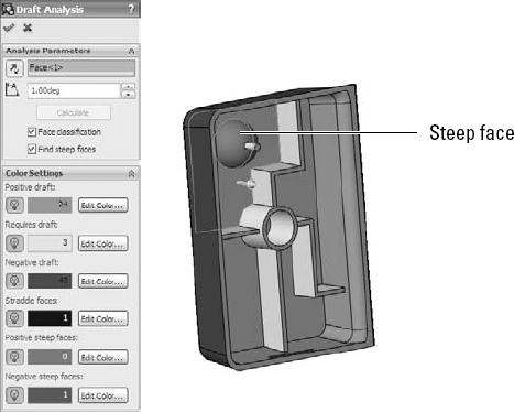
Face Classification draft analysis groups the faces into classifications using solid, non-transitioning colors. You will notice a big difference between the coloration of the Face Classification draft analysis faces and of the Basic or Gradual Transition faces. Face Classification uses OpenGL face shading, which is the same as that used by SolidWorks by default. This allows for better shading and differentiation between faces that face different directions. The Basic Analysis coloration looks like all the faces are painted the same flat hue, regardless of which direction they are facing, which makes shapes more difficult to identify. The non-Open GL alternate shading method makes it possible to display a transition in color. SolidWorks OpenGL shading cannot do this.
Another advantage of using the OpenGL shading is that the face colors can remain on the part after you have closed the Draft Analysis PropertyManager.
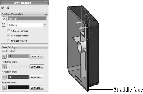
Face Classification draft analysis also adds a classification that is not used by the Basic draft analysis. Straddle faces refer to faces that straddle the parting line, or faces that, due to their curvature, pull from both halves of the mold. These are faces that need to be split. On this part, a straddle face is shown in Figure 32.15.
The light bulb icons to the left of the color swatches enable you to hide faces by classification. This is useful when you are trying to isolate certain faces, or visualize a group of faces in a certain way. This can be an extremely useful feature, especially when you have a very complex part with a large number of faces, some of which may be small and easily lost in the mix with other larger faces.
The face counts that appear in the color swatches are a very helpful feature that is absent from the Basic draft analysis.
Best Practice
I prefer Face Classification draft analysis because it is the clearest. If I need additional detail regarding other types of faces, then I may run a Steep Face draft analysis as a supplement. The best practice here is not that you follow my favorite type of draft analysis, but that you understand what you need to know and then use the appropriate tools to find this information. This may include running multiple analyses to collect all the necessary information.
A steep face is defined as a face that transitions from less than the minimum angle to more than the minimum angle. Steep faces are different from straddle faces in that straddle faces are actually positive and negative, while steep faces are either entirely positive or entirely negative. On this part, the dome inside the part is classified as a steep face, as shown in Figure 32.16.
Note
The tools from the Utilities add-in are always listed in the Tools menu, whether or not the add-in is loaded. When any of the tools is selected, the add-in is automatically loaded. SolidWorks has also done away with the Utilities menu, so if you are accustomed to using this functionality from previous versions, some new functionality awaits you.
You can run Thickness Analysis in two modes: Show Thin Regions and Show Thick Regions. Of these, Show Thick Regions is the most versatile.
The Show Thin Regions option, or the "Thinness" Analysis, requires you to input a minimum acceptable thickness. Every face with a thickness above this value is turned a neutral gray, and every face with a thickness below this value is displayed on a graduated scale.
Figure 32.17 shows the PropertyManager for this analysis and its result on the same part used for the draft work in the previous sections.
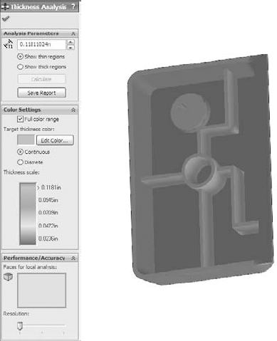
One of the things to watch out for here is that some anomalies occur when you apply this analysis to filleted faces. The faces shown as colored were created by the Shell feature and should be exactly .100 inches thick. However, it does correctly represent the undercut on the end of the part and the thickness of the ribs. A nice addition to this tool would be the identification of minimum thickness faces. Perhaps you can submit an enhancement request.
The Show Thick Regions option works a little differently from Show Thin Regions. You need to specify an upper thickness limit value, beyond which everything is identified as too thick. In these examples, the nominal wall thickness of the part is shown as .100 inches, and the thick region limit is set to .120 inches. For this type of analysis, the color gradient represents the thicknesses between .100 inches and .120 inches, while in the Thinness Analysis, the color gradient represents the values between .100 inches and 0 inches.
The analysis can produce some anomalous results, especially at the corners, and also in the middle. Again, this is a useful tool, if not completely accurate. You can use it to find problem areas that you may not have considered, but you should certainly examine the results critically.
The Treat Corners As Zero Thickness option should always be selected. I have never seen a situation where selecting it improved the results; in fact, I have found that deselecting it has always made corners and fillets behave worse.
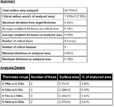
This feature can generate a report, which to some extent answers questions about how or why it classifies faces in the way it does. To get a complete picture of the situation, it may be useful to look at the report when you are using the results to make design or manufacturing decisions. A sample of the report is shown in Figure 32.18.
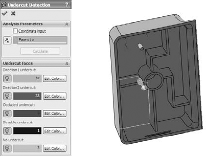
Even if you and your mold builder know that a part has absolutely no undercuts, the Undercut Detection tool will nonetheless always identify all the faces to be undercut. In fact, the only faces that this tool will identify as not undercut are faces that have no draft on them. The only time it correctly identifies an undercut is when it classifies the undercut as Occluded Undercut. Faces that have no draft and are occluded undercut are improperly identified as simply No Undercut.
You may want to avoid this tool because too much interpretation of incorrect results is necessary; however, if you still want to use it, here is a translation guide that may help:
No Undercut. Should read No draft in the primary draft direction, but may be occluded undercut faces
Occluded Undercut. Should read Occluded Undercut faces that have draft in the completely irrelevant primary draft directions; does not include occluded undercut faces that have no draft in the primary direction
Figure 32.19 shows the PropertyManager for this function and the results. If you would like to test it for yourself, the part is on the CD-ROM with the filename Chapter 32 Draft Analysis.sldprt.
The SolidWorks Mold Tools are intended to help you create cavity and core blocks for injection molds. They do not provide libraries or functionality for building the entire mold or mold components. Mold Tools entail a semiautomatic process to follow, with the tools in order on the toolbar. Mold Tools rely heavily on surfacing, and require a fair amount of manual intervention for certain types of parts. The next section deals with the manual intervention techniques. This section deals with the idealized semiautomatic process.
In order to fully understand the formalized Mold Tools process, it might be helpful to understand SolidWorks' capabilities with mold geometry in general. First, understand that to create cavity and core geometry in SolidWorks, you are not required to use the Mold Tools. You can manually model surfaces or solid features to accomplish the same tasks. Surface features are widely used for mold modeling because they allow you far more control than solid features.
You can also make mold geometry using an assembly of in-context parts or multi-body techniques. The formal Mold Tools functionality uses the multi-body approach. This has benefits and drawbacks.
With the formal SolidWorks process, you start in part file with just the final plastic part in it, and then build both the cavity and core blocks around the plastic part. You also build any side actions or core pins within the part file.
Figure 32.20 shows the part of the Mold Tools toolbar that identifies the process. From the left to the right, the icons are:
Split Line
Draft
Move Face
Scale
Insert Mold Folders
Parting Lines
Shut-off surfaces
Parting Surfaces
Tooling Split
Core
Mold Tools are really meant for tooling engineers, but part designers often use the first part of the process to apply draft to parts. Tooling engineers often need to add or correct draft to plastic parts they receive from part designers without draft or that are not designed with any process in mind whatsoever.
Cross-Reference
The Split Line feature was covered in Chapter 7, and is not covered again here. Draft was covered earlier in this chapter.
The general workflow for using Mold Tools to create cavity and core blocks for an injection mold is as follows:
Create split lines to add draft where needed.
Create draft as needed (Move Face can be used to angle faces much like the Draft feature).
Scale the part up to compensate for shrinkage during molding.
Identify the parting lines that separate cavity faces from core faces.
Create Shut-off faces, which are surfaces that close any through holes (windows or pass-throughs) in the part and represent places where the steel from the cavity side of the mold directly touches steel from the core side of the mold. These openings in the part are capped by surface features.
Create Parting surfaces. These are the faces outside the part where the steel from opposite sides of the mold touch.
Create the Tooling Split. Tooling Split uses the faces of the Shut-offs and Parting Surfaces, and the faces of either the Cavity or the Core side to split a block into two sides.
Create any Core features. Core is an unfortunately named feature in SolidWorks. Even in mold lingo, the word has several meanings, and it doesn't become any clearer when translated into SolidWorks terminology. In this case, the word "core" refers to the material used to make core pins, side action, slide, lifter, or pull in a mold.
If you were to create a mold with manual modeling functions, you might go through roughly the same steps in the same order. The SolidWorks process often breaks down in the automated surface modeling areas, such as shut-offs and parting surfaces. You may need to manually intervene in the process for these steps. Fortunately, the SolidWorks process is flexible enough to allow for manual modeling as needed.
Each one of these process steps may have several steps of their own. Cavity and core creation is far from a push-button operation, but when you understand the overall process, the detailed steps become clearer.
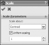
Some materials have anisotropic shrink rates, meaning they shrink different amounts in different directions. SolidWorks has a means to compensate for this, although it may not always be practical. Usually the shrink directions are identified as "in the direction of flow" and "across the direction of flow," and the direction of flow of molten plastic inside a mold cavity is not always a straight line. Any anisotropic shrink applied to a part in SolidWorks is an approximation at best. If you deselect the Uniform scaling option in the Scale feature, SolidWorks enables you to set different scale factors for X, Y, and Z directions. The Scale PropertyManager is shown in Figure 32.21.
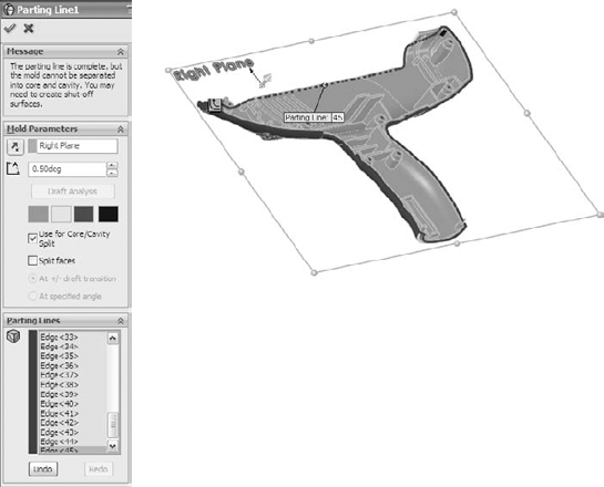
In the example shown here SolidWorks gives me a message that says that the parting line is a complete loop around the part, but the part has some through holes, so it requires shut-off surfaces to close the holes.
The Parting Lines feature can also split faces if need be. You might need to split a face that straddles the parting line. For example, a filleted face might bridge across the parting line and need to be split.
When you initiate the Shut-off Surfaces feature, SolidWorks identifies some of the necessary shut-offs for you. Figure 32.23 shows this.
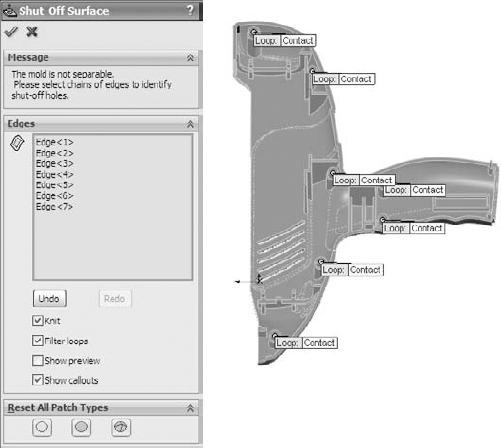
When all appropriate edges around all the holes and slots are selected, the Shut-off Surfaces PropertyManager message window turns green and says "The mold is separable into core and cavity."
The tags on the loops in the graphics window will say either "No Fill," "Contact," or "Tangent." No Fill means that you do not want SolidWorks to create the shut-off surfaces. You will do these manually. Sometimes shut-off surfaces require complex or multi-feature shut-offs, which you have to do manually. The Contact condition means that the shut-off surface just needs to touch the edges, usually at a right angle. Tangent should be obvious.
Sometimes you need a combination of conditions in a single shut-off, in which case you will need to finish the feature manually. When the parting line and shut-off surfaces are complete, SolidWorks will automatically knit together all the surfaces in each Cavity and Core folder into a single surface body.
There are not enough options with this feature to make it work in most situations in which it doesn't work by default. What this boils down to is that for 70 percent or more of your Parting Surfaces, you will need to create your own manually, which I show you how to do in the next section.
Just to show an example that does work, I have created a very simple part and brought it to this point using the Mold Tools process. When the process works as it should, and even when you have to create surfaces manually, you will wind up with one complete surface body in each of the Mold Tools Folders — Cavity, Core, and Parting surfaces. From this you can see that the Parting Surface and Cavity Surface define the top side of the Cavity block. Likewise, the Parting Surface and the Core Surface define the top side of the Core block.
In Figure 32.24, the Parting Surface is transparent so you can see both the Cavity and Core surface bodies. The grayscale image may not show this distinctly, but if you open the part from the CD-ROM, it will become obvious.

Figure 32.25 shows the PropertyManager for the Tooling Split feature, along with a preview of the feature. The feature will produce two solid bodies, representing the cavity and core blocks of the mold. This model is included on the CD-ROM, under the name Chapter 32 – frame mold tools.sldprt.

A tooling engineer would probably change a few things about the layout of this split, but for the purposes of learning how the tools work, this is sufficient. The Parting Line of the front part of the device should probably face forward instead of up to prevent as much vertical steel in the mold as possible.
To send the cavity and core blocks to a shop for mold building, you will probably want to separate the multi-body part into individual part files. Use the techniques from Chapter 26 for this (Save Bodies, Insert Into Part, Insert Into New Part).
Note
To check the cavity and core blocks to make sure that they make the shape desired, make a new block that is larger than the original part, making sure to deselect the Merge Result option. Then use the Combine tool to subtract the mold parts from the new block. Then use the inverse scale to shrink it back down to finished part size (1original scale factor).
Also note the Interlock surface option in Figure 32.25. Most if not all of the examples of molds that you see created with SolidWorks mold tools are going to employ parting line interlocks. This is not because most molds are built that way, but because it is the main way that SolidWorks gets around the limitations in the Parting Line functionality.
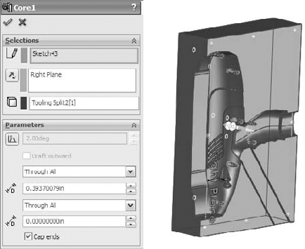
You can either pre-create a sketch or just make a sketch when the Core feature asks you for it. The Core feature is looking for a sketch that will cut out the block of mold material that you want to make a core of. Again, you can use this for side cores or core pins. In this case, I want to make several core pins.
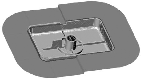
To start, activate the Core feature; then sketch circles centered on each of the screw boss cores in the Cavity body. When I exit the sketch using the Confirmation Corner, SolidWorks prompts me for an extrusion depth for the sketch to create the feature. The Core PropertyManager and the feature preview are shown in Figure 32.26.
Again, you can save out these core pins as individual part files. You can use similar techniques to create side cores or lifters or other types of side actions.
You have already seen that any sort of mold modeling resembling even a moderately complex part requires some level of manual intervention to get the Mold Tools to deliver usable results. You can do the entire mold modeling process manually, without using any of the semiautomated tools from Mold Tools. You may even come across situations where you do not need to use surface modeling at all. These situations will tend to be parts with a planar parting line, with no shut offs or cores.
I know several experienced mold designers, and they all tend to use different techniques, from cutting away chunks with solids, to using all manual surfacing methods, to using about 80 percent Mold Tools techniques and the rest manual surfacing. To me, it makes most sense to use the Mold Tools for the things they are good at, because they do speed up some tasks, such as planar shut-offs and separating out the cavity and core faces.
I want to run through two examples of manually intervening in the Mold Tools process. In the first, I will show you how to create a passing shut-off (shut-off with a stepped parting line), and in the second, I will show you how I created the Parting Surface shown in Figure 32.24.
Snap features are often achieved in molds by using passing shut-offs rather than some sort of a lifter or horn pin slide. Eliminating actions from a mold can be economical, as long as the passing shut-off does not introduce wear or alignment problems. When creating parts that require this sort of feature in the mold, it is a good idea to consult your mold builder.
Passing shut-offs can be difficult to visualize, even for seasoned professionals. It might be a good idea to open up the part on its own and see the geometry for yourself. The filename on the CD-ROM is Chapter 32 – passing shut off start.sldprt. This is a clip that holds a CD in place in a plastic case. The draft analysis colors have been left on it to help you see which faces belong to which side of the mold. There are no undercuts on this part, as shown in Figure 32.27.
In this part I have actually modeled two pair of passing shut-offs.
Using the rollback bar is probably the best way to see what is going on with this part. The surfacing involved here may be confusing to you if you are not well versed with surfacing, but looking at the part and understanding the steps will help you learn. The basic steps to create the surface body called Shut-off 1 are as follows:
Create Ruled surface for the planar edges.
Loft surfaces between the parting line edges and the Ruled surface.
Extrude a flat shut-off face at the parting line of the snap feature.
Use the Cavity or Core knitted body to trim the extruded surface.
Use the extruded surface to trim the ruled and lofted surfaces.
Knit the surface bodies together.
The hardest part of creating this passing shut-off is visualizing what the interface between the steel from opposite sides is going to look like. It is best to keep it as simple as possible. Tool builders request a wide range of angles for the passing shut-off (mold steel touching at steeply angled faces). I have heard them say that the minimum draft they can possibly stand is anywhere from 5 to 15 degrees of draft. I try to give at least 8 degrees, and more if I can. The tool builder will also look for a minimum land on the top of the shut-off boss, generally not less than 1 mm, or approx 0.050 inches, to work with round numbers.
Don't be discouraged if you don't completely understand this the first time around. The concept itself is difficult, and visualizing the geometry is extremely difficult.
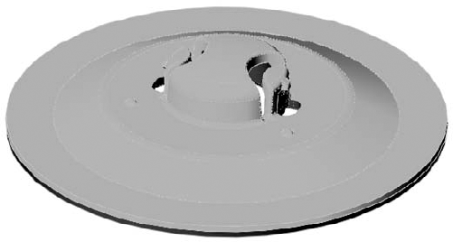
Frankly, the method SolidWorks uses to create the Parting Surface is insufficient for most tasks. It will work well if you are molding a range of Frisbees or dinner plates, but it will not work well for handheld medical devices. Figure 32.28 shows the part on the CD-ROM named Chapter 32 – frame parting surface.sldprt. The result is entirely unacceptable for several obvious reasons.
From this you can learn that the SolidWorks Mold Tools are not reliable for concave parting lines or non-planar parting lines. Flat parting line disks and boxes work well. Beyond that, expect to need to do some manual surface modeling.
Note
If you want software that will do automatic parting surfaces for you, consider MoldWorks and SplitWorks from R&B software. This software also includes highly automated mold libraries and aids to help you model and document every aspect of mold hardware.

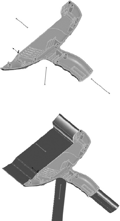
To manually create the parting surfaces for this part, I tackled the hard part first, which turns out to be easy once you know a couple of tricks. The first thing I did was to create a sketch and use it to lay out directions that I could pull off the non-planar sections of the parting line. Figure 32.29 shows three lines that identify the non-planar top, base of grip, and trigger areas. The sketch lines lead in directions that those edges could be projected without running into other geometry.
Then the edges of each non-planar portion of the parting line were converted into sketch entities in a 3D sketch, and extruded as a surface along each of these three directions. From there, it was simple to create planar surfaces between the non-planar sections. This technique may not work for all non-planar parting lines, but it does work for this one.
This tutorial walks you through adding several plastics features to a simple part, running some plastics evaluations on it, and then making the cavity and core blocks for the mold using a couple of different techniques. The goal of the tutorial is to make you familiar with the workflow of the tools rather than to teach every available option.
To create a simple plastic part, start by opening a new SolidWorks part file.
Draw a Centerpoint Rectangle on the Top XZ plane centered on the Origin, 4 inches (vertical) by 6 inches (horizontal).
Extrude 1 inch with 2 degrees of draft, using the Draft Outward option.
Apply fillets to the vertical edges with 0.5 inch radius.
Apply a fillet to the face nearest the Origin with a 0.25 inch radius.
Draw a circle on the Top plane centered on the Origin with a 0.75 inch diameter, and extrude it through the part as a cut, using 2 degrees draft, without the Draft Outward option.
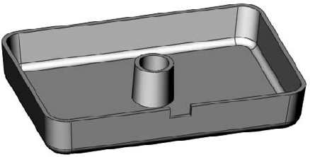
Shell the part with a 0.10 inch thickness, removing the top face (large end of the extrusion).
Draw a centered rectangle on the Front plane 0.25 inch deep by 0.5 inch wide where the top of the rectangle is coincident with the top edge of the part. Cut through one side of the shelled block. To do this without cutting the boss in the center of the part you will have to use the From panel, extruding from an offset of 0.5 inch. Your model should look like Figure 32.30.
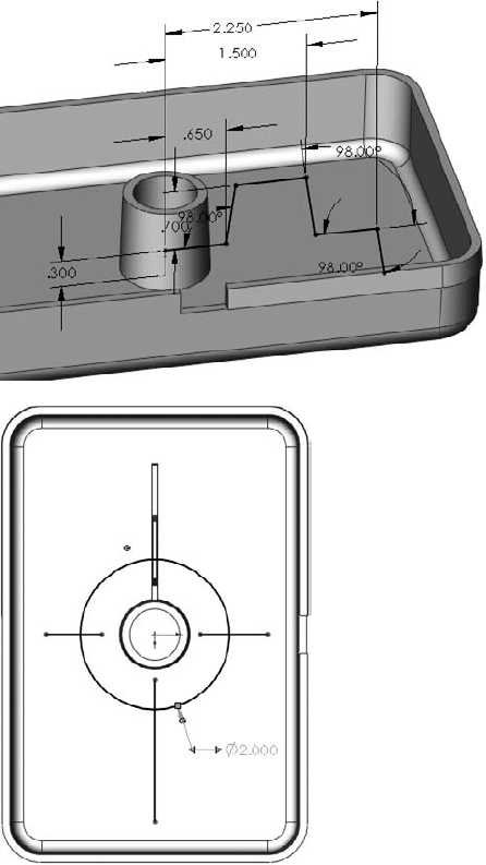
To create a Split Line, on the Front plane, draw a line from the bottom-right corner of the rectangular notch cut in Step 8 horizontally off the right side of the part. Make sure it goes past the part. Draw another short line from the bottom-right corner of the rectangular notch so that it makes a 100-degree angle with the horizontal line.
Use a Split Line to split all the faces that the lines project onto (should be a front, a back, two fillet faces, and a side for five total faces). Figure 32.31 shows the Split Line and the sketch.
To create a Step Draft, initiate a Draft feature. Use the Step Draft option. Select Perpendicular Steps. The draft angle should be 2 degrees. The direction of pull is the top thickness face of the box. Parting lines are the six edges of the split. Make sure all the yellow arrows are pointing to the same side of the split edges. Figure 32.32 shows the Step Draft in action.
Note
You need to pay attention to the direction of the arrows for the draft (pointing up) and the selected faces (also pointing up). These arrows can have a mind of their own, and when you change one, it often changes the others without asking if that's what you want to do. You may have to individually select edges from the Parting Lines box and click Other Face to get all the arrows pointing in the right directions.
Click OK to accept the feature. Notice the drafted face steps out from the main part faces. Take a moment to examine the result of the Step Draft.
To create Rib features, on the Front plane, create a sketch like the one shown in Figure 32.33. Initiate a Rib feature, and make it 0.075 inch wide at the base (by selecting the At Wall Interface), with 1 degree of draft. Make sure you are using the Parallel to Sketch option (skyline).
Open a sketch on the horizontal face of the rib that is 0.3 inch above the Origin, as shown on the lower image of Figure 32.33, and create the sketch shown, with a complete circle crossed by three lines.
Create another rib. This time use the Perpendicular to Sketch (plan view) option. The thickness is again 0.075 inch at the base with 1 degree of draft. The part at this point should look like Figure 32.34.
Add the Mold Tools to your CommandManager (right-click a tab and select Mold Tools), or if you are not using the CommandManager, turn on the Mold Tools toolbar (by right-clicking on a toolbar and selecting Mold Tools).
To scale the part, add a Scale feature with a factor of 1.008. Scale about the Origin of the part.
To initiate the Parting Line tool, use the Top plane as the Pull Direction, and set the draft angle to 1 degree. Click the Draft Analysis button.
Notice a purple parting line goes all the way around the part, but a warning message appears at the top of the Parting Line PropertyManager. The warning says that the parting line is complete, but you need to also create a shut-off surface. Figure 32.35 shows the Parting Line PropertyManager and the model at this point.
You might also notice that the two side faces of the notches don't have draft. For now, go ahead with creating the mold with the faces like this, and as an exercise, come back later and add the draft and watch it propagate through the surface features into the mold blocks.


Note
You may need to deselect some edges around the rectangular notch. The edges selected for the Parting Line should be a clean single loop of edges that always separate the red faces from the green or yellow faces. Be careful that the Parting Line goes around the Step Draft faces correctly.


Click the green check mark button to accept the Parting Line feature.
To create Shut-off faces, click the Shut-off Surface tool on the toolbar. It should automatically find the hole in the middle of the part and understand where the shut-off needs to go. Click the All Contact icon at the bottom of the PropertyManager and then click the green check mark button to accept the feature.
In the FeatureManager, expand the Surface Bodies folder. Notice that it has subfolders for Cavity and Core Surface Bodies.
To create the Parting Surfaces, click the Parting Surface icon in the CommandManager. Assign a distance of 2 inches, and make sure that it automatically picked up the Parting Line feature. The Mold Parameters option should be set to Perpendicular to Pull.
Examine the preview of the Parting Surface. Notice that it looks good, but not perfect. In this case, you will call it "good enough," although the angled lines around the rectangular cut out are not really "good enough." Ideally, you might remodel that face later, given it should all be theoretically planar anyway. Notice how the surface handles the stepped parting line created by the split line feature and the Step draft.
Click the green check mark button to accept the feature. The part at this point is shown in Figure 32.36.
Click the Tooling Split icon in the CommandManager.
Select the Top plane, and draw a centerpoint rectangle centered on the Origin so that it is 6 inches by 8 inches, and the sketch fits within the bounds of the parting surface. Make sure that you are looking at the part from the Top view.
Exit the sketch by using the pencil icon in the ConfirmationCorner. This enables the Tooling Split feature to continue.
View the part from the side, and change the depth numbers at the top of the Tooling Split PropertyManager so that the block goes down .5 inch and up 1.5 inch. Accept the feature when you are done.
Right-click on the blue parting line in the graphics window and select Hide. Also hide solid and surface bodies so you can see the inside of the block.
Look at the finished part provided on the CD-ROM if you need a reference. Use the controls on the Display Pane to hide and show bodies. Also use the Isolate option on right mouse button menus for the bodies folder and the body in the graphics window.
SolidWorks provides a vast amount of plastics functionality. In this chapter, I've given you an introduction but there is far more for you to learn as you go. These features will become second nature after you have used them a couple of times. The power and flexibility is amazing when you think of the incredible range of parts that you can make with these features.
SolidWorks Mold Tools, by contrast appear immature, but you can complete the mold process multiple ways, including using manual surfacing techniques. Rarely does a problem come up such that there is simply no way to do what you need to get done, but you do need to be inventive with work-arounds sometimes.