In SolidWorks software, visualizing geometry is part of the overall mission of the software. Visualizing 3D CAD data is more than seeing shaded solids or shiny surfaces; it includes being able to see the interior and exterior at the same time and using sections, transparency, wireframe, and other tools. In AutoCAD, the visualization is entirely in your head. You have to imagine what the 3D looks like given the 2D views. SolidWorks takes it so much further than just being able to see things in 3D; you can look at some parts of an assembly in wireframe while others are transparent and others are opaque. You can see a part with a reflective appearance. You can create section views in parts and assemblies to visualize internal details.
My aim with this chapter is to show you important capabilities that will expand your SolidWorks knowledge, at the same time, provide some of the awe and wonder we sometimes experience while using incredible 3D tools to do actual work. I start with visualization tools and pass through to some more advanced visualizations tools and techniques. If I sound a little enthusiastic about this topic, it is because visualization is the part of this software that really brings your imagination to life. It can be the source of real inspiration and allows you to communicate geometrical ideas with other people.
One of the most important skills in SolidWorks is manipulating the view. This is something you'll do more frequently than any other function in SolidWorks; therefore, learning to do it efficiently and effectively is very important, whether you look at it as rotating the model or rotating the point of view around the model. The easiest way to rotate the part is to hold down the middle mouse button (MMB) or the scroll wheel and move the mouse. If your mouse does not have a middle button or a scroll wheel that you can use as a MMB, then you can use the Rotate View icon on the View toolbar, or the icon on the Heads-up View toolbar. The Heads-up View toolbar is shown in its default state in Figure 5.1.
The Heads-up View toolbar can be customized and disabled using the same method that you use for all other toolbars, through the Tools
Tip
Some mouse drivers change the middle-button or scroll-wheel settings to do other things. Often, you can disable the special settings for a particular application if you want SolidWorks to work correctly and still use the other functionality. For example, the most common problem with mouse drivers is that when the model gets close to the sides of the graphics window and the scroll bars engage, the middle mouse button suddenly changes its function. If this happens to you, you should change the function of the MMB to Middle Mouse Button from its present setting.
You can use the arrow keys on the keyboard to manipulate the view in predictable and controllable ways. You can use the Shift, Ctrl, and Alt keys to add to the behavior.
The arrow keys enable you to rotate to the following views:
Arrow. Rotate 15 degrees. To customize this setting, choose Tools

Shift+arrow. Rotate 90 degrees.
Alt+arrow. Rotate in a plane flat to the screen.
Ctrl+arrow. Pan.
Most, if not all, mice sold today have middle mouse buttons (MMBs), usually in the form of a clickable scroll wheel.
The MMB or scroll wheel has several uses in view manipulation:
MMB alone. Rotate.
Click or hover on edge, face, or vertex with MMB, and then drag MMB. Rotate around selected entity.
Shift+MMB. Zoom.
Double-click MMB. Zoom to fit.
Scroll with wheel. Zoom in or out. To reverse direction of the zoom setting, choose Tools
Alt+MMB. Rotate in a plane flat to the screen.
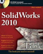
Mouse gestures are an interface method that you can customize to do anything a SolidWorks toolbar button can do, but by default, it controls view orientation. Figure 5.2 shows the default configuration of the mouse gesture donut.
It may take a little time for you to get used the interface. It works best when you understand what the commands are before you use them, so that you can invoke the Top View command in a single motion. It does not work well if you have to initiate the interface with a very short RMB drag, then drag again to select the command. For this reason, it might be better to limit the donut to four commands rather than eight, and set it up intuitively such that the top view is a RMB stroke up, a right view is a RMB stroke to the right, and so on.
You can customize the mouse gesture donut in the Tools
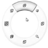
The View toolbar, shown in its entirety in Figure 5.3, contains the tools that you need to manipulate the view in SolidWorks. Not all of the available tools are on the toolbar by default, but I have added them here for this image. To customize your own View toolbar, you must use choose Tools
An option exists to add scrollbars and view pane splitters to the graphics window. To use it, choose Tools
Figure 5.4 shows a detail of the bottom-right corner of the SolidWorks graphics window, where you find the scrollbars and splitters. Notice the cursor in the lower right over one of the splitters. The splitters can be easy to miss if you do not know what they look like.

The splitters enable you to split the main graphics window into multiple view ports. The options are two ports horizontally, two ports vertically, or four view ports. The splitter bars are located at the intersection of the scrollbars in the lower-right corner of the graphics window. Of course, you can also use the icons on the Standard Views toolbar for splitting the view into two vertical ports, two horizontal ports, or four ports, the Heads-up View toolbar, or the View Orientation flyout.
Once a viewport has been split, you can remove the split with the toolbar icons, either by dragging the border back to the edge of the display window or by double-clicking the split border. If the view has been split into four, you can set it back to a single viewport by double-clicking the intersection of the horizontal and vertical port borders.
You can invoke the Magnifying Glass by pressing G, and dismiss it when you select something or when you press Esc. To change the hotkey it is associated with, choose Tools
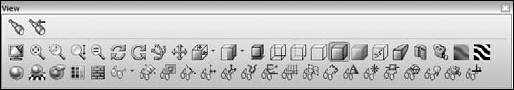
The magnified area follows your cursor as it moves, and you can zoom in and out by scrolling the MMB. Ctrl and dragging keeps the Magnifying Glass centered on the cursor. Pressing Alt creates a section view parallel to the view, and scrolling with Alt pressed moves the section plane further away or closer. Figure 5.5 shows the Magnifying Glass in operation, cutting a section view through a part.
Note
The intended purpose of the Magnifying Glass is to select small items. You may use it to inspect things, but remember it will disappear as soon as you select something.
The Triad is the multicolored coordinate axis in the lower-left corner of the SolidWorks graphics window. You generally use it passively to see how the view is oriented and to get X, Y, Z reference directions for features that need it.
To use the Triad to control the view orientation, try the following:
Click an axis. This axis will point out of the screen.
Click an axis a second time. This axis will point into the screen.
Shift-click an axis. This view will spin 90 degrees about that axis (using the right-hand rule).
Alt-click an axis. This view will spin 15 degrees (or the default view rotation angle) around the axis.
When you are in a named view, a little box in the lower-left corner shows the name of the view. This includes standard named views and custom named views. Anything that shows up in the View Orientation box (accessed by spacebar) displays a name in the corner. Figure 5.6 shows the Triad and the named view box in the lower-left corner.
By Shift-clicking an axis of the triad, the view is rotated 90 degrees from the original orientation. Alt-clicking rotates the view around the clicked axis by the view rotation increment set in Tools
Manipulating the view is one of the most important and commonly used methods to help you visualize a CAD model to which users have access. SolidWorks has a very wide range of tools, mostly represented by the tools on the View toolbar.
The tools in this section will help you to view parts and assemblies. The following tools are mainly found in the View


Zoom about Screen Center. Enables you to zoom straight in and straight out. This tool is off by default. The default behavior is that zooming works around the cursor. If the cursor is off to one side, zooming in and out can cause the view to "walk" away from that side. This command is only found in the menus at View


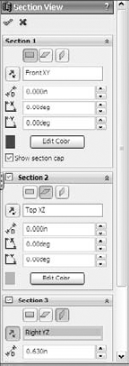
Clicking the check mark icon in the Section View PropertyManager enables you to continue working with the sectioned model, although you may not be able to reference edges or faces that are created by the section view. It is only a displayed section; the actual geometry is not cut.
Section Views can be saved either to the View Orientation box or to the Annotation View folder, which enables section views to be reused on the drawing. Annotation Views are described in more detail in Chapter 22.


Cameras are created through the RMB menu on the Lights, Cameras and Scene folder in the FeatureManager, as shown in Figure 5.8. When you add a Camera, an interface displays in the PropertyManager, as shown in Figure 5.9.


In this interface, you can position the Camera object by dragging the triad, and you can resize the Field of View box by dragging the border. In the graphics window, you can use the left panel to target and position the Camera, while the right panel shows the view through the Camera.
The Depth of Field panel of the Camera PropertyManager is not shown, because it requires that PhotoWorks be added in. Depth of field can make objects outside of the focus area slightly out of focus, which can greatly add to the realism of renders.
There are three methods to switch the graphics window to the Camera view:
Through the View Orientation dialog box (accessed through the spacebar)
Through the View Orientation popup (in the lower-left area of the graphics window)
Through the RMB menu on the Camera in the Lights, Cameras and Scene folder in the FeatureManager
When you switch the view to the Camera view, the regular Rotate View command does not function. Rotating the view means moving the Camera. You can move the Camera by editing the Camera properties, reposition the Camera by dragging the triad, or rotate the view while looking through the Camera using the Turn Camera tool.

Viewing the model from a particular point of view.
Creating renderings with perspective and depth-of-field (focus) blur; this feature is only available when PhotoWorks is added in.
Animating the position and target of the point of view in an animation. This feature is only available when a Motion Study is active.


Warning
Perspective view and sketching do not work well together. Sketches and dimensions will look distorted and incorrect with perspective turned on. I recommend disabling perspective view when sketching.
Performance
Settings in Tools
The three cases that Zebra Stripes can help you identify are as follows (see Figure 5.10):
Contact. Surfaces intersect at an edge, but are not tangent across the edge. This condition exists when stripes do not line up on either side of the edge.
Tangency. Surfaces are tangent across an edge, but have different radius of curvature on either side of the edge (non-curvature continuous). This condition exists when stripes line up across an edge, but the stripe is not tangent across the edge.
Curvature continuity. Surfaces on either side of an edge are tangent and match in radius of curvature. Zebra Stripes are smooth and tangent across the edge.
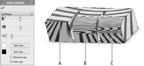
In Figure 5.10, the Zebra Stripes in example A do not match across the edge labeled A at all. This is clearly the non-tangent, contact-only case. Example B shows that the stripes match in position going across the indicated edge, but they change direction immediately. This is the tangent case. Example C shows the stripes flowing smoothly across the edge. This is the curvature continuous case.
You can use the remaining icons in the View toolbar to toggle the display of various types of entities from reference geometry to sketches.
Tip
Consider using hotkeys to toggle the display of your favorite items to hide and show. I use T for Temporary Axes, P for Planes, R for Origins, and so on.
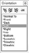
The Standard Views flyout is called either Standard Views or View Orientation, depending on where you see it. The View Orientation dialog box contains the following controls:
I have already mentioned the Standard Views flyout on the View toolbar, but here I describe the tools it contains in detail. Figure 5.12 shows the Standard Views toolbar in its default configuration.

By default, the Standard Views toolbar contains the View Orientation button, a tool from the View toolbar. The View Orientation button is discussed in detail earlier in this section.
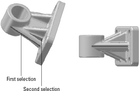
First Mode. Click a plane, planar face, or 2D sketch. When you click Normal To, the view reorients normal to the selected plane, face, or sketch, and zooms to fit the model in the view. This method is shown in Figure 5.13.
Second Mode. Click Normal To a second time. The view rotates 180° to display the opposite direction.
Third Mode. After making the first selection, Ctrl+select another planar entity. The view is normal to the first selection and the second selection is rotated to the top. This method is shown in Figure 5.14.

Annotation views enable you to group annotations that were made in the 3D model into views that will be used on the drawing. They are collected under the Annotations folder in the FeatureManager for parts and assemblies. Annotation views can be created either automatically, when 3D annotations are added, or manually. An Unassigned Items annotation view acts as a catchall for annotations that are not assigned to any particular views. In the 3D model, you can use the views to reorient the model and display annotations. As mentioned earlier, annotation views can also capture a model section view to be shown in a drawing view. The Annotation views are shown for the Chapter5SampleCasting part in Figure 5.15.

RealView is a hardware-driven set of visualization tools that help make the SolidWorks display look more realistic, adding reflections, reflected backgrounds, and shadows. RealView is intended to help the user apply advanced effects to 3D models. The fact that RealView is hardware-driven means not all video cards that are certified to work with SolidWorks also work with RealView. You need to check on the SolidWorks Web site to see what level of RealView your graphics card supports. A link to the video card testing site should be available from the SolidWorks home page at www.solidworks.com.
In some situations, you can use RealView instead of rendering. In these cases, RealView acts as a real-time renderer. The main advantages that rendering software such as PhotoWorks or PhotoView 360 holds over RealView are improved antialiasing control, improved shadow control, indirect illumination, global illumination, caustics, and effects such as depth of field from a camera.
You can even use RealView as a diagnostic tool for smooth transitions between surfaces because RealView appearances apply a reflective surface to a part and then apply a reflective background. This is essentially what the Zebra Stripes functionality is doing, but Zebra stripes applies a specific reflective background to make examining curvature continuity across edges more straightforward.
You can turn RealView on or off by using the golden sphere icon shown by default on the Heads-up View toolbar. If this icon is grayed out, then your system is not equipped with an appropriate RealView-capable graphics card. Generally, you need an nVidia 500 series or higher to get RealView capabilities, and an appropriate graphics driver must be installed with the hardware. NVS series cards are not 3D cards and will not enable RealView. Some ATI FireGL cards may also work.
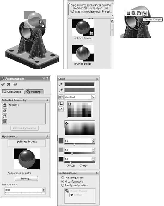
RealView consists of appearances and scenes. The Appearances section controls colors, textures, reflectivity, optical properties, and materials. The Scenes controls the background image and reflectivity image. Figure 5.16 shows the contents of the RealView tab in the Task Pane, as well as the callout that appears when you drop an appearance onto a part. The callout enables you to select whether you want the appearance applied to the face, body, part, or assembly level.
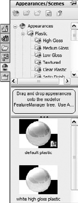
To apply an appearance, use the Task Pane at the right of the graphics window, and click the Appearances tab. Figure 5.17 shows this. Then select an appearance from the list and drag it onto the part where you would like to apply it. You can do this either in the part window or in the assembly window. A small popup will appear and present you with options for what to apply the appearance to, which is the face, feature, body, or part.
Appearances also enable you to change colors. To change the color of an applied appearance, use the Appearance Callout icon on the RMB menu, select the level you want to apply the color to (face, body, feature, part), and then select the color from the Appearance PropertyManager. Figure 5.17 shows the Appearance PropertyManager.

One of the things that confuses many users about applying an appearance is that it can be applied on many levels, and may override or be overridden by other appearances. This means that in a part, an appearance may be applied to a face, a feature, a body, or the entire part. There is a specific hierarchy to this system of overrides: part, body, feature, face, component, and automatic color changes.
When you apply an appearance at the level of the part (the name of the part shows in the Color and Optics PropertyManager), any other entity color will override it. You can assign Solid or Surface bodies an appearance that overrides the part appearance. Some color changes are automatic; for example, when you are editing parts in the context of an assembly, they can temporarily change color or become transparent, which overrides everything else.
Note
The Edit Sketch or Curve Color works for sketches and limited curve features. It works for all curve features except for projected curves. In addition, pre-selection does not work with this tool. The Edit Sketch or Curve Color tool is grouped with the commands in the View toolbar in the Tools
The Display pane flies out from the right side of the FeatureManager and displays a quick list of which entities have appearances, transparency, or other visual properties assigned. It also shows hidden parts or bodies for assemblies and multibody parts. The Display pane is shown in Figure 5.18. I revisit the Display pane in Chapter 12 to show you how it is used in assemblies.

You can access tools to remove appearances in two separate locations. The first is the Appearance flyout on the context toolbar for either left- or right-clicking on a model (the Appearance flyout is only available on the RMB menu if you have not disabled the context toolbar for shortcut menus).
The second location is in the Appearances PropertyManager. Both of these locations are shown in Figure 5.19.
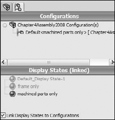
One of the most commonly used and powerful visualization aids available in SolidWorks is the Display States functionality (see Figure 5.20). Display States is simply the capability to show parts shaded, shaded with edges, wireframe, HLR (hidden lines removed), or HLG (hidden lines in gray).
Cross-Reference
Chapter 14 deals with Display States in more detail.
In addition to being able to use display states to differentiate parts in an assembly, you can use display states for bodies within parts. I only mention the capabilities in this chapter because display states are a huge tool for visualization in both parts and assemblies. Examples of the functionality applied to real modeling situations will come in Chapters 12 through 16 for assemblies and Chapter 28 multi-body topics.

Earlier in this chapter, I discussed the Shaded with Edges display style. Some people think that this makes the parts look "cartoony." I agree, especially when the default black edges are used, but the display improves when the edge color matches the shaded part color. In any case, sometimes this method is necessary to see the breaks between faces, especially fillets. Cartoony or not, it is also useful.
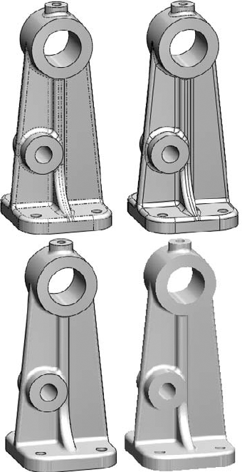
Taking this one step further, you can also make use of the tangent edge settings. These settings are found in the View
Tangent Edges Visible. Displays tangent edges as solid lines, just like all other edges
Tangent Edges as Phantom. Displays tangent edges in a phantom line font
Tangent Edges Removed. Displays only non-tangent edges
The tangent edges removed setting leaves parts looking like a silhouette. I prefer the phantom setting because I can easily distinguish between edges that will actually look like edges on the actual part and edges that only serve to break up faces on the model. The tangent edges visible setting conveys no additional information, and is the default setting. Figure 5.21 shows a sample part with all three settings.
You can expand or collapse subassemblies by clicking the assembly symbol at the top of the tree, or you can disable the color display by clicking the color gradient scale. Value bars can also be displayed to show the relative value of each assembly component.
Figure 5.22 shows a model of a bicycle sorting subassemblies by mass. The gray value bars are superimposed on the text in the FeatureManager area. You will have to open an assembly on your computer and try this for yourself to see the color display.

Figure 5.22. Assembly Visualization offers several ways to sort and display the components in an assembly.
You can access the Assembly Visualization tool on the Evaluate tab of the CommandManager when an assembly is active. The toolbar icon is with the Tools icons, and you can find it by choosing Tools
Visualization is a key factor when working with SolidWorks software. Whether it is for a presentation of your design to customers or management or simply checking the design, it is important to be able to see the model in various ways. This tutorial guides you through using several tools and techniques.
If the part named
Chapter5Sample.sldprt is not already open, open it from the CD-ROM. If it is open and changes have been made to it, choose FilePractice using some of the controls for rotating and zooming the part. In addition to the View toolbar buttons, you should also use Z and Shift+Z (Zoom Out and In, respectively), the arrow keys, and the Ctrl+, Shift+, and Alt+arrow combinations.
Use the MMB to select a straight edge on the part, and then drag it with the MMB. This rotates the part about the selected entity. Also, apply this technique when selecting a vertex and a flat face.
Select the name of the part at the top of the FeatureManager.

Click the color you want in the Favorite panel. The model should change color. If you click and drag the cursor over the colors, the model changes color as you drag over each new color. You can also drag appearances from the Task Pane. Figure 5.23 shows interfaces for both methods.
If the Color panel is not expanded, click the double arrows to the right to expand it. Select the colors you want from the continuous color map. Again, click and drag the cursor to watch the part change color continuously.
Create a swatch. In the Favorite panel, select the Create New Swatch button and call the new swatch color file
BibleColors.Select a color from the Color Properties continuous map; the Add Selected Color button becomes active. Clicking the button adds the color to the swatch palette. You can add several colors to the palette to use as favorites later on.
Tip
You will be able to access these colors again later by selecting
BibleColorsfrom the drop-down list in the Favorite panel. You can transfer the colors to other computers or SolidWorks installations by copying the fileBibleColors.slddclrfrom the<SolidWorks installation directory>langenglishfolder (or the equivalent file for your installed language).In the Appearance panel, move the Transparency slider to the right, and watch the part become transparent.
To prevent the Appearance window from closing after every change, click the pushpin at the top of the window.
Click the green check mark icon to accept the changes; note that with the pushpin icon selected, the window remains available.
Expand the flyout FeatureManager in the upper-left corner of the graphics window, as shown in Figure 5.24, so that all the features in the part are visible.
Select the features Extrude1, Fillet7, and Fillet6 from the FeatureManager so that they are displayed in the Selection list of the Appearances window. Select a color from the BibleColors swatch palette that you have just created.
Click the check mark icon to accept the changes and clear the Selection list.
Select the inside face of the large cylindrical hole through the part and assign a separate color to the face.
Click the check mark icon to accept the changes, and click the red X icon to exit the command.
Expand the Display pane (upper-right area of the FeatureManager). You should see color and transparency symbols for the overall part, and color symbols for three features. There is no indication of the face color that is applied.
Remove the colors. Open the Appearances window again, re-select the three features (Extrude1, Fillet7, and Fillet6), and click the Remove Color button below the Selection list. Do the same with the colored face. Return the part transparency to fully opaque.
Click the check mark icon to accept the changes.
Change the edge display to Shaded (without edges). Then change to a Wireframe mode. Finally, change back to Shaded with Edges.
Choose View
DisplayTangent Edges as Phantom. Figure 5.25 shows the difference between Tangent Edges Visible, as Phantom, and Removed settings.

Tip
Using the Tangent Edges as Phantom setting is a quick and easy way to look at a model to determine whether face transitions are tangent. It does not help to distinguish between tangency and curvature continuity; you need to use Zebra Stripes for that.
Switch back to Shaded display.
If you do not have a RealView-capable computer, then skip this step. Ensure that the RealView button in the View toolbar is depressed. Click the Appearances/Scenes tab on the Task Pane to the right of the graphics window. Expand Appearances
Turn the part over, select the bottom face, and drag and drop the appearance from the Task Pane. Apply the appearance just to the bottom face using the popup toolbar that appears. The rest of the part should retain the semi-reflective surface, as shown in Figure 5.26. Click the check mark icon to accept the change.
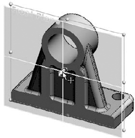
Click the Section View button on the View toolbar. Drag the arrows in the middle of the section plane back and forth with the cursor to move the section dynamically through the part, as shown in Figure 5.27.
Select the check box next to the Section 2 panel name and create a second section that is perpendicular to the first.
Click the green check mark icon to accept the section. Notice that while in the Section View PropertyManager, the RealView material does not display, but once you close the dialog box, RealView returns.


This tutorial walks you through the steps necessary to make use of the Assembly Visualization tool in SolidWorks.
Close other open documents by choosing Window
Close All command. If you have any documents open from the CD-ROM, you can save them using the Save As command.Open the assembly file
BibleBikeAssembly ch5.sldasmfrom the CD-ROM.

Click each available heading to see the tree sorted based on that criteria.
Turn off the assembly coloration by clicking once on the red to blue fade.
Sort the tree based on mass.
Show the tree in flat rather than nested display.
Move the red and blue sliders up and down to focus on a range of weights.

Visualization is a key function of the SolidWorks software. It can either be an end to itself if you are showing a design to a vendor or client, or it can be a means to an end if you are using visualization techniques to analyze or evaluate the model. In both cases, SolidWorks presents you with a list of tools to accomplish the task. The tools range from the analytical to the cosmetic and some of the tools have multiple uses.