
Advanced Topics
The preceding chapters on disks cover the fundamentals of today’s disk drives. In this chapter, some more advanced topics will be discussed. These are new concepts and approaches that are significantly different from current methods of doing things. As such, they are above and beyond simply making evolutionary improvements over current technologies. While no attempt is made to create an exhaustive list of all such topics, the topics selected here are deemed to be important for the reader to be aware of. The topics run the gamut from fundamental magnetic recording physics (perpendicular recording), to recording media (patterned media), to heads (thermally assisted recording), to servo (dual stage actuator), to data format (adaptive formatting), to caching (hybrid HDD), and all the way up to drive interface and storage subsystems (object-based storage). Some of these technologies are already starting to be incorporated into disk drives that are being shipped today. Some will be in products in the near future. Others may not be in any product plans yet, but look promising to be worth some discussion here.
25.1 Perpendicular Recording
In 2005 a couple of disk drive manufacturers had announced their intentions to deliver products using perpendicular recording. Currently, in 2007, all major disk drive manufacturers are shipping some drives in perpendicular recording. Longitudinal recording is expected to be phased out within the next few years.
In Chapter 17, where the fundamentals of magnetic recording were discussed, the discussions assumed longitudinal recording which have been exclusively in use for the past 50 years. In longitudinal recording, the magnetization for representing data bits is in the plane of the recording medium. Thus, the magnetic domains are lying down along the path of each track, as illustrated in Figure 25.1(a). These domains can remain stable in such a configuration because the magnetic medium is fabricated to have an easy axis parallel to the disk surface so that it is natural to assume a horizontal position. However, as the bit size decreases due to increasing areal density, the amount of energy required to reverse the polarity of a recorded bit becomes less and less. Eventually, the point will be reached when mere excitations from ambient thermal energy would be sufficient to cause the magnetic grains making up a recorded bit to spontaneously “flip,” i.e., reverse magnetic orientation. When enough numbers of the grains within a bit have flipped, the state of the bit’s polarity becomes ambiguous and therefore unreadable. Data storage is no longer feasible without thermal stability. This point is known as the superparamagnetic limit.
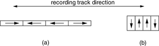
FIGURE 25.1 Two magnetic recording methods: (a) longitudinal recording and (b) perpendicular recording.
There is no simple physical law that precisely dictates at what recording areal density the superparamagnetic limit would occur. It is governed by many complex interacting factors, including the materials used for the recording medium and the write head; the design of the write head; the parameters used during the write process, such as flying height and write current; etc. Back in the 1970s, it was conjectured that the limit would be reached at around 25 Mbits/in2. Research and innovations over the years have been able to continually push this predicted limit out by orders of magnitude. The use of higher coercivity recording material has been one of the key factors. Today’s disk drives are operating close to 100 Gbits/in2. However, there seems to be a consensus that longitudinal recording will be hitting its limit in the near foreseeable future.
A different recording technology holds promise to pack magnetic recording bits much closer without encountering thermal instability, thus extending the superparamagnetic limit further out. This technology is perpendicular recording1 [Hoagland 2003; Iwasaki 1980, 1984, 2002; Suzuki & Iwasaki 1982, Honda et al. 2002]. As the name implies, in perpendicular recording, magnetization is normal to the plane of the recording medium. The magnetic domains are standing up along the path of the track, as shown in Figure 25.1(b). This is the result of the recording medium being fabricated to have an easy axis perpendicular to the disk surface so that it is natural for the recorded bits to assume a vertical position. From a simplistic point of view, it is easy to see why, at high density, perpendicular recording is more stable. With longitudinal recording, at the transition point where magnetization polarity reverses, two like poles are facing each other. The magnetic repelling action between the two domains naturally tends to try to flip each other. On the other hand, with perpendicular recording, opposite poles which attract each other are next to each other on the two sides of a transition.
25.1.1 Write Process, Write Head, and Media
Although the implementation details of perpendicular recording present a different set of challenges from those of longitudinal recording, conceptually, perpendicular recording is not all that different from longitudinal recording; just that magnetization is rotated by 90°. Thus, not surprisingly, the write processes of the two recording methods are quite similar. In fact, the discussion in Chapter 17, Section 17.1.4, on the principle of writing in longitudinal recording is applicable to perpendicular recording if the externally applied magnetization field in the plane of the magnetic medium is replaced by one that is normal to the plane of the magnetic medium. The series of drawings in Chapter 17, Figure 17.6, would then becomes as illustrated in Figure 25.2.

FIGURE 25.2 Write process example for perpendicular recording. (a) Medium before writing. Write magnetic field applied to (b) first compartment, (c) second compartment, (d) third compartment, and (e) fourth compartment. (f) Magnetic pattern in medium after writing.
It is theoretically possible to use the ring head described in Chapter 17, Section 17.2.3, to do the writing in perpendicular recording. The vertical component of the trailing edge of its write bubble would provide the magnetic flux to align the grains of the medium whose easy axis is perpendicularly oriented. The current state of the technology is to use a modification of the ring head, called the single pole head.2
The principle of the single pole head is the same as that of the ring head. However, its geometry, as illustrated in Figure 25.3, is modified to produce a more vertical magnetic field for use in perpendicular recording. To achieve a vertically oriented magnetic flux emanating from the write pole tip and propagating into the magnetic medium, the gap between the two poles of the head is substantially widened from that of the ring head. This gap is considerably larger than the head’s flying height. Furthermore, in order to maintain this perpendicular orientation all the way through the medium, the magnetic flux lines should not turn in its return path back to the return pole until it has exited the medium. This is facilitated by adding a relatively thick layer of magnetically soft material underneath the recording medium. This soft underlayer (SUL), made of high-permeability material such as CoFeB alloys, allows the flux of the write head to flow freely between the two poles. Therefore, the SUL is, in reality, a part of the head structure, even though physically it is located in the disk platter. The SUL material, thickness, and separation from the write pole must be an integral part of the design of a single pole head for perpendicular recording. An advantageous effect of the SUL is that it acts like a mirror and produces a reflected image of the head on the other side of the medium/SUL interface. This reflection results in doubling the recording field going through the medium.

FIGURE 25.3 A single pole head in conjunction with a soft underlayer used in perpendicular recording. How the head is used for writing transitions is also illustrated.
In addition to having an easy axis normal to the plane of the disk, perpendicular media are thicker than longitudinal media. Materials with a higher coercivity are also used, such as CoPtCr-oxide. This is possible because for the same amount of current, the single pole head in conjunction with the SUL can deliver roughly twice as strong a magnetic field for recording as a ring head. High coercivity improves thermal stability. It is also amenable to having sharper transitions being written, thus supporting higher linear density. Finally, the magnetically soft nature of the SUL material can have a destabilizing effect on the recorded medium. Therefore, a very thin exchange break layer (EBL) is placed between the recording layer and the SUL to reduce the magnetic interactions between them.
25.1.2 Read Process and Read Head
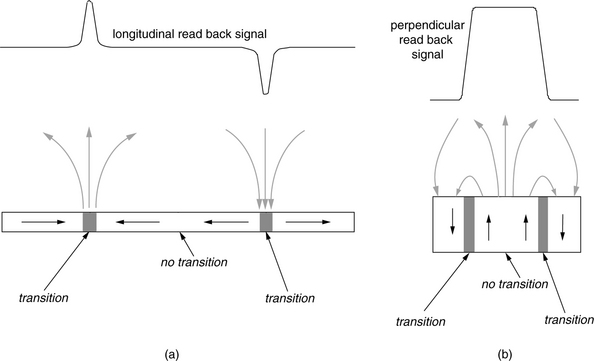
Similar to longitudinal recording, perpendicular recording also uses a transition to represent a 1 and the absence of transition to represent a 0. The read process is, therefore, one of detecting transitions. MR, or GMR, heads are also used in perpendicular recording. As discussed in Chapter 17, Section 17.2.3, MR heads are fabricated with an easy axis such that it senses external magnetic field in the vertical direction. With longitudinal recording, the maximum vertical magnetic flux emanating from the medium is at a transition, as shown in Figure 25.4(a). This results in pulses at the transitions in the read-back signal of the MR head. On the other hand, in the case of perpendicular recording, vertical magnetic flux occurs in between transitions. Thus, the read-back signal from the MR head approximately looks like a square wave, as illustrated in Figure 25.4(b). However, by taking the derivative of this signal, a pulse signal resembling that of the longitudinal recording read-back signal is obtained. Thus, by adding a signal differentiator circuit in the read channel, the rest of the signal detection circuitry can be adapted from longitudinal recording.
25.2 Patterned Media
Perpendicular recording can push the superparamagnetic limit out, perhaps to about 500 Gbits/in2. To attain higher areal density beyond that, more radical technologies are being explored. One front runner is patterned media [Hughes 2002].
25.2.1 Fully Patterned Media
In patterned media, each recording domain or bit is physically separated from each other so that the magnetic interaction between neighboring bits can be limited, thus improving thermal stability. The idea is simple: carve a ditch around each square domain to isolate it, as illustrated in Figure 25.5. By creating individual islands of magnetic domains, the bit size will be reduced to just 1 magnetic grain, much smaller than that of traditional continuous recording which typically consists of 100 magnetic grains per bit, and yet still be thermally stable. To turn this idea into practical reality, there are three significant challenges to overcome.

FIGURE 25.5 A conceptual illustration of patterned media recording. Each island, topped with magnetic recording material, is a recordable bit. Each row represents part of a track.
The first challenge is how to make the disk platters and make them cheaply. To create the island features on the surface of a disk, some kind of lithography will likely be used. The feature size for areal densities greater than that of current technology is smaller than what optical lithography, which is what is used for making integrated circuits in the electronics industry, is capable of delivering. For instance, at an areal density of 1 Tbit/in2, the center-to-center spacing between islands would be 27 nm. Thus, electron beam (e-beam) or ion beam lithography will likely need to be used. A layer of resist material on a stamper substrate will be exposed to an e-beam or ion beam in accordance to the desired pattern. After developing the exposed resist layer and then etching, a stamper having the mirror image of the desired patterned media features will be created. The stamper, or mold, can then be used in a process known as nano-imprint lithography (NIL) to mass produce disk platters having the final physical features. This process involves pressing the stamper on a thin layer of soft polymer resist material on the surface of the disk substrate and, at the same time, curing it with ultraviolet light. Finding the right material that will adhere to the disk substrate and yet separate cleanly from the stamper is key to this process. As a final step, magnetic recording material will be deposited on top. Magnetic material, in addition to being deposited on the top of the islands, will unavoidably also end up in the ditches surrounding the islands, but that will have a negligible effect in the recording process since it is further away from the head.
The other two challenges are related to the process of writing and reading those magnetic islands of the patterned media. One of them is tracking. In current conventional recording, tpi is several times smaller than bpi, as discussed in Chapter 19, Section 19.3. In other words, the bits are wider than they are long. With patterned media, the ideal case is to have square bits so as to maximize areal density. This means that tpi will increase much more than bpi if conventional recording is transitioned to patterned media recording. To handle the much narrower tracks, the mechanical servo system will have to be substantially improved over today’s in order keep the head on track for both reading and writing.
In today’s conventional recording, the position of a bit is not predefined. Rather, it is defined by the write head during the write process. Thus, the location of a bit when it is written may not be precisely the same every time. Some small amount of deviation is likely. This is possible because the magnetic recording material is continuous throughout the entire disk surface. Deviations are tolerated and adjusted by the read process as the clocking information as well as the data are written by the same write head. However, with patterned media, the position of a bit is predefined on the disk. To produce a proper magnetic recording, the writing by the head will have to be more precise than conventional recording so that it is synchronized to the individual islands.
While either longitudinal or perpendicular recording can be used in patterned media recording, it is most likely that perpendicular recording will be employed. At extremely high areal densities, perpendicular recording should have better thermal stability.
25.2.2 Discrete Track Media
A halfway step from today’s continuous recording to patterned media recording is discrete track media recording. Instead of fully patterning every individual recording bit on the media, only individual tracks are patterned. Since only a groove is used to separate tracks from each other, as illustrated in Figure 25.6, instead of ditches around each individual bit, discrete track media should be easier to manufacture, at least during the infancy stage of learning how to pattern disk media. Since recording along each track is still continuous, discrete track recording does not have to solve the write synchronization problem of patterned media.

While discrete track media does not have all the benefits of fully patterned media, the magnetical separation of adjacent tracks provides the following advantages.
• Reduced interference from neighboring tracks will improve signal-to-media noise ratio.
• A stronger write field can be used for writing, resulting in a stronger read-back signal, thus improving signal-to-electronic noise ratio.
• Write head tolerance can be more relaxed, improving manufacturing yield and efficiency.
• Similar to patterned media, head position servo information can be placed on the media at the time of manufacture of the discrete track media. This would save having to do servo write during the final assembly of the disk drive.
25.3 Thermally Assisted Recording
Another front runner in advanced technologies being researched to further push back the superparamagnetic limit is thermally assisted recording, also referred to as heat-assisted magnetic recording (HAMR). Magnetic material with higher coercivity is more thermally stable, since more energy is required to reverse its magnetic polarity. Thus, it is desirable to use materials with as high a coercivity as possible for increasing areal density without the problem of thermal instability. However, by its very nature, a stronger magnetic field is required to perform magnetic recording on such materials, perhaps beyond what the write head can deliver. Cranking up the write current being applied to a write head to induce a stronger magnetic field for writing may generate too much heat and damage the head.
The basic idea of thermally assisted recording is based on the principle that coercivity of a magnetic material is temperature-dependent; it goes down as the temperature rises. For some materials, the dependency is small within any practical temperature range. For others, there is a significant decrease in coercivity when the temperature is increased by a few hundred degrees Celsius. In thermally assisted recording, the magnetic recording media will be made of such materials. The temperature of the bit to be written is rapidly raised just before the head is ready to write it. After the bit has been written, it is immediately cooled down so that its coercivity reverts back to its original high value. The resulting recording will then have the good thermal stability advantage of a high-coercivity medium which normally cannot be written with a conventional recording technology.
While the concept is simple, there are clearly several challenges that must be solved.
Material The right material to be used in thermally assisted recording needs to be found. The ideal material should have a coercivity versus temperature dependency that looks something like that shown in Figure 25.7. First, it should have a rather sharp change in coercivity over a small range of temperature change. Second, this sharp change must occur at a temperature above the normal operating temperature of the drive and yet not be too high so that it can be reached fairly quickly and with practical means. Thus, a range between 100 and 200°C is a good target. Third, its cool temperature coercivity should be high, e.g., 6 KOe, while its hot temperature coercivity should be low, e.g., 1 KOe.

FIGURE 25.7 Coercivity versus temperature characteristic of ideal material for thermally assisted recording.
Heating process The heating process for the bit to be written has to be very precise and well controlled. Ideally, only the bit being written should be heated up, and as soon as it has been written, it should be cooled down very rapidly. At a data rate of 100 MB/s, or 1 Gbit/s, a bit is written in 1 ns. Thus, the heating and cooling cycle is required to have a response time in that order of magnitude. A laser light will likely be used to provide the heat source. For this reason, thermally assisted recording is also known as optically assisted recording. In order not to heat up neighboring bits, the spot size of the laser needs to be kept small. At an areal density of 1 Tbit/in2, for instance, the diameter should not be larger than 27 nm.
Recording head A new type of head with an integrated laser and small spot optics will have to be designed. Needless to say, the head-disk interface (HDI) of such new head structures will also have to be studied. The manufacturing process will have to be engineered.
Thermally assisted recording, when ready to move out of laboratories and be deployed in actual disk drive products, will likely be used in conjunction with patterned media. The two techniques together may possibly be able to push the superparamagnetic limit out to beyond tens of terabits per square inch.
25.4 Dual Stage Actuator
The function of the servo system, as discussed in Chapter 18, Section 18.5, is to position the drive’s actuator accurately over the track being accessed. As track density increases, the tolerance of the servo system becomes tighter and tighter. This creates two challenges for the traditional actuator. First, there is a limit to how much positioning accuracy can be attained by using the VCM to move the relatively massive comb actuator. Second, in order to maintain the head centered over the track throughout a data access, the servo system needs to monitor the position error signal that gets generated at every servo burst and responds to it by moving the actuator using the VCM. However, the frequency with which adjustments can be made is limited by the mechanical resonance of the VCM actuator. This performance capability of a servo is quantified as the servo bandwidth. A tight tolerance means an actuator with high servo bandwidth will be required. For these reasons, current actuator technology will be severely challenged to meet future tpi requirements, such as those introduced by perpendicular recording and patterned media.
One promising approach for increasing the servo bandwidth is the use of a dual stage actuator [Semba et al. 1999, Huang et al. 2002, White et al. 2004]. In fact, this technology is starting to appear in some disk drive products being shipped today. As the name implies, the dual stage actuator consists of components that allow positioning to be achieved in two stages. This concept was conceived more than 10 years ago. In the first stage, the traditional VCM driven actuator is used to make a large distance coarse seek from one location of the disk to another, moving the entire E-block comb actuator and all the heads that it carries in the process. In the second stage, a new element in the system will perform the fine positioning of the head. This second stage actuator moves only one of the heads, instead of the entire comb actuator holding all the heads.
Researchers have been looking into three distinctly different approaches and configurations for the second stage actuator:
Moving suspension The first method is to locate the secondary actuator at the junction where the root of the suspension beam meets the end of the actuator arm and swing the whole suspension. By moving the suspension, the slider and the head are moved. Such actuators are typically made using a PZT (piezoelectric transducer).
Moving slider The second method is to insert the secondary actuator in between the suspension and the slider. The slider is moved by the secondary actuator, while the suspension is stationary.
Moving head The third method is to integrate the secondary actuator to the slider and mount the read/write head directly to it. Only the head gets moved.
The locations of these three types of secondary actuators are shown in Figure 25.8. The first method still requires moving a relatively flexible suspension beam, and the maximum servo bandwidth gain will be limited by its resonant modes. The third method has the potential to produce the highest bandwidth gain. However, fabricating such an actuator and integrating it with the magnetic head will be difficult. The second method seems to be the best compromise of offering good bandwidth gain and yet be reasonably implementable. Thus, it is currently the preferred approach.

FIGURE 25.8 Locations of different types of secondary actuator: (a) moving suspension, (b) moving slider, and (c) moving head.
With a dual stage actuator, the servo control circuit shown in Chapter 17, Figure 17.34, needs to be modified. First, a driver circuit needs to be added for the secondary actuator. Second, the servo control logic now needs to coordinate the movements of the primary and secondary actuators. The VCM controls the low-frequency, large-stroke motion, and the secondary actuator controls the high-frequency, small-amplitude motion. The challenge is in handling the mid-frequency hand-off region in a manner such that the two actuators do not interfere destructively. It is important that the secondary actuator does not waste its limited stroke opposing the VCM.
25.4.1 Microactuators
The secondary actuator of the moving slider method is referred to as a microactuator. Its small dimension makes it amenable to being fabricated using MEMS (micro-electro-mechanical system) technology. Within the microactuator approach, three distinct technologies are being pursued by various drive vendors and component manufacturers. The differences arise from how electrical power is converted into mechanical power to move the slider.
PZT based With this technology, a U-shaped microactuator with PZTs on either side of its prongs is used to hold and move the slider, as shown in Figure 25.9. When voltage is applied, one of the PZTs expands, while the other contracts as a result of the reverse piezoelectric effect. This causes the prongs to bend, thus moving the slider cradled between them. Reverse the polarity of the voltage applied, and the prongs will bend in the opposite way.

Electromagnetic based Conceptually, this approach is basically to create a miniaturized VCM, possibly fabricated using MEMS technology. Electromagnetic force is generated to move the attached slider by passing current through a coil in the presence of a permanent magnet, both of which are built in the microactuator. When designing this type of microactuator, care must be taken to ensure that no magnetic field leaks out to interfere with either the read or the write process of the head.
Electrostatic based This type of microactuator is moved using electrostatic force. While varying designs are possible, in the common comb-drive design, teeth on the side of a movable rotor are arranged facing an interlacing set of opposing teeth on a fixed stator. This is illustrated in Figure 25.10(a). With the rotor grounded, and applying a voltage to one of the two stators, the electrostatic attraction between the opposing teeth creates the force for moving the rotor. The slider is thus moved as it is mounted on the rotor. The amount of physical motion is extremely small; the resulting movement of the head is on the order of a few microns. Apply voltage to the other stator, and the rotor will move in the opposite direction. Rotational motion results if the rotor is suspended in the center. Linear motion results if the rotor is suspended at its corners. Figures 25.10(b) and (c) show a prototype for an electrostatic microactuator.

Microactuators are estimated to have about three to five times the servo bandwidth of traditional single stage actuators. Thus, the dual stage actuator approach should be able to handle several times higher tpi than traditional VCM actuators alone.
25.5 Adaptive Formatting
As areal density goes higher and higher, the head dimension gets smaller and smaller. A tiny variation in manufacturing a head’s geometry can result in an observable variance in performance from the norm. Other parameters such as track width can also be affected. Growth in areal density becomes more and more limited by such variation in head performance and component tolerance. The traditional method for handling heads having different profiles coming off manufacturing lines is to sort the heads and HGAs based on soft error rate performance and track width. Different heads are then allocated to disk drive products with different capacity design points. The logistics plan of using such an approach is complex, making production output difficult to plan and predict.
A technique, invented several years ago, is now starting to become more widely adopted. With this method, heads of different performance characteristics are allowed to co-exist within the same disk drive. Each head operates at the bpi that it is capable of handling, i.e., producing a signal-to-noise ratio such that the net soft error rate falls within the design requirement. Thus, a higher performing head will operate at a higher bpi, and a lower performing head will operate at a lower bpi. The number of sectors per track, and hence data rate, varies as a result, depending on the head.
In one implementation of this technique, the tpi of all the heads remains the same. This approach is usually adopted by drives using the cylinder mode formatting. Since the number of tracks per surface is constant, the capacity of each disk surface is then dependent on the head. However, all drives need to have the same total capacity. That means a drive with some lower performing heads must be balanced by also having some higher performing heads. A drive with all lower performing heads will not be able to deliver the needed total capacity. Thus, while this approach for adaptive formatting provides a certain degree of leeway in manufacturing, it does not offer 100% flexibility.
In another implementation, the tpi varies along with the bpi from head to head. This technique can only be applied with the banded serpentine formatting, discussed in Chapter 18, Section 18.3.3, and illustrated in Figure 18.5(b). A higher performing head has a wider track width, which is why it gets a stronger signal. Conversely, the track width for a lower performing head is narrower. Thus, higher bpi is coupled with lower tpi, and vice-versa. The product of the two is roughly constant, resulting in the same areal density. The number of tracks within each serpentine band of each surface will depend on the head. The same is true for the number of sectors per track. However, the total number of sectors within a band will be constant, or roughly constant, from surface to surface. For example, one surface may have 90 tracks in one band, with each track holding 1000 sectors. Another surface may have 100 tracks in that same band, but each track only holds 900 sectors. Yet, both surfaces have 90,000 sectors per band. This approach is more flexible, since it can have any mix of heads within the same drive, even all lower performing heads, and still be able to deliver the same total drive capacity.
Hence, adaptive formatting improves manufacturing efficiency. However, the user needs to realize that there may be variance in performance, especially data rate, from head to head and also from drive to drive.
25.6 Hybrid Disk Drive
In 2005, Microsoft submitted to the T13 technical committee for inclusion in the next ATA-8 standard a proposal for a new class of disk drives which incorporate a non-volatile cache inside the drive. To be more precise, the proposal was for a new set of commands for interfacing with such devices. This gives the host machine some control over how the non-volatile cache in the drive is to be used and managed. This new type of storage device is a hybrid disk drive because it will contain two different types of non-volatile memory: the magnetic media and the non-volatile cache.
25.6.1 Benefits
The expected benefits of a disk drive with a nonvolatile cache are:
1. Improved power management When a drive has been spun down to save power during a period of inactivity, any new write command received from the host can be written to the non-volatile cache without having to spin up the drive. Such writes are accumulated either until the non-volatile cache is full or when the drive needs to be spun up for other reasons, such as to do a cache-miss read. Since spinning up the drive consumes a considerable amount of power, this is especially beneficial in a mobile system which runs on battery power.
2. Improved drive reliability Spinning up and down the drive can add to its wear and tear. By reducing the number of such cycles, the reliability of the drive can be improved. Also, the shock resistance of a drive is much higher when it is spun down and its heads are safely unloaded. In reducing the amount of time the drive is spinning, its exposure to shock damage is reduced.
3. Faster boot and application loading times By saving the boot image and the state of the system into the non-volatile cache when a machine is either shut down or put into hibernation, the next machine startup can load from the non-volatile cache without having to wait for the drive to be fully spun up and ready to read, which can take seconds. Similarly, applications that are stored in the nonvolatile memory can be loaded into the system more quickly.
25.6.2 Architecture
The new proposal does not specify the architecture for the new hybrid disk drive, so different designs and implementations are possible. Neither does the proposal specify what technology is to be used for the non-volatile cache. At this point in time, flash memory is the most likely candidate, in part due to its relatively low cost. In the future, other technologies such as MagRAM or MEMS memory [Carley et al. 2000, Albrecht et al. 2004] may be better choices.
The high-level architecture for a flash-based hybrid Hard Disk Drive (HDD) will likely look something like that shown in Figure 25.11. The flash memory will be placed on the internal data bus alongside the DRAM buffer/cache. There are several shortcomings with flash memory that the designer needs to be aware of and take into consideration while architecting a hybrid drive.

1. Page write Writing to flash memory generally has to be done in pages. The page size depends on the flash technology used and the manufacturer.
2. Erase before write A block, consisting of multiple pages, must first be erased before it can be written. Erasure time is very slow.
3. Limited write cycles Current flash technology has a limited number of cycles that each bit can be written, typically around 100,000 times. There are two general approaches for handling this limit. The first one is wear-monitoring, in which the number of write cycles for each block of flash memory is monitored. A block that has reached its limit will be permanently mapped out and made unavailable for further use. A second approach is wear-leveling, in which all the blocks in the flash memory are managed such that they all get used evenly. This usually means using the flash memory in a circular fashion.
4. Low data rate Flash write data rate is about an order of magnitude lower than that of a magnetic disk, read data rate is about one half, and erasure takes milliseconds. Thus, performance is lower compared to disk access when transferring a large amount of sequential data.
25.6.3 Proposed Interface
The non-volatile memory is used as a cache to the drive, rather than an extension to the drive’s address space. The main salient feature of the proposed interface is the definition of a non-volatile cache pinned set. The host system can specify to the hybrid drive a set of LBAs that are to be pinned in the cache. An “Add LBAs to pinned set” command is used to add a new range of LBAs to the set, and a companion “Remove LBAs from pinned set” command is to unpin a range of LBAs. Spaces left over in the non-volatile memory are free to be used by the drive for write caching or other internal uses.
An interesting feature of the “Add LBAs to pinned set” command is the “Populate Immediate” flag. If this flag is set in the command, the drive is to prefetch the content of the LBA range from the disk. This usage is envisioned for the pinned set to be used for preloading boot files into the non-volatile cache in preparation for a shutdown and the next reboot. If the flag is not set, then the drive will take no action to fetch data from the disk into those locations. Rather, it is anticipated that the host will send down write data to those LBAs. An example of this usage model is the writing of the hibernation file in preparation for the host system going into hibernation. After either a cold reboot or a wakeup from hibernation, the previously pinned LBAs can be unpinned and freed up for write caching use.
The proposed interface for nonvolatile cache can be found in the draft document “AT Attachment 8—ATA/, ATAPI Command Set (ATA8-ACS)” of the T13 Standard Committee (see www.T13.org). It is expected that the proposal will officially be adopted as part of ATA standard by the end of 2007. Microsoft’s new Vista operating system supports hybrid HDDs, although at this time no hybrid HDDs are generally available from any disk manufacturer for evaluation yet.
25.7 Object-Based Storage
A disk drive, like all other digital storage devices, understands that it is being asked to store and retrieve bits of 0’s and 1’s. A disk drive is not cognizant of the meaning of the data that it is handling. With today’s block interface, a drive is asked to read or write blocks of data, with each block being some multiple of its physical sector size. It does not know, or care, whether the block is part of a directory, part of a file, or a complete file. While this paradigm makes the storage device easier to implement and keeps the interface simple, from a system point of view it is not the most efficient.
A more efficient disk architecture would be for the disk drive itself to be cognizant of the space allocation aspect of the file system being used to manage its storage space. With such knowledge, it can perform lookahead prefetch much more intelligently and accurately. This would improve the effectiveness of the disk drive’s cache. Furthermore, a user can access his data in the disk more directly without entailing all the file system directory lookup and update traffic going back and forth between the host and the drive. These and some other benefits can be derived from the proposed object-based storage device (OSD3) architecture [Mesnier et al. 2003].
In 1999, the OSD Technical Working Group was formed to create a self-managed, heterogeneous, shared storage architecture by moving low-level file storage functions into the storage device itself. The storage device would be accessed using a new object-based standard interface instead of the traditional block-based interfaces of SCSI or ATA. Building on work originating from the Network Attached Storage Devices project of the National Storage Industry Consortium (NSIC) and the Network Attached Secure Disk project at Carnegie Mellon University, the group developed requirements, standard definitions, and prototype demonstrations for OSD storage subsystems. The working group was later adopted by the Storage Networking Industry Association (SNIA), and collaboration with the ANSI T10 technical committee was established in 2000. Since mid-2004, OSD has been a standard extension to SCSI approved by T10.
Because it is defined as a new command set, it can be used on standard SCSI physical interfaces. This also means OSD architecture can be implemented either natively in a disk drive or in some higher level storage controller. So far, OSD exists mostly on paper only. For OSD to be generally adopted and embraced by the storage industry, it will require a massive amount of operating system changes, particularly file systems and databases. New storage devices with the OSD interface implemented will be needed too, naturally. Major software houses are not likely to produce OSD-enabled software until OSD hardware is generally available, while major storage vendors are not likely to manufacture such devices until software is available to use them. Some catalytic event is likely to be needed for OSD to break out of this catch-22 mode.
25.7.1 Object Storage Main Concept
The main idea of OSD is fairly simple. Each piece of user data, e.g., a file or a database record, and its associated metadata (information describing the data, such as its size) are handled together as one single object. Each object possesses a set of user accessible attributes. An object, instead of a logical block, is the unit of data access between a host and an OSD. A user is allowed to access any number of bytes at any offset within an object. With the traditional block-based interface, a user accesses his data basically using either a “read block” or a “write block” command. In OSD, a user accesses his data using a “read object” or a “write object” command. Additionally, a user directly issues “create object” and “delete object” commands to an OSD. There are also commands available for the user to get and to set the attributes of an object.
The OSD standard allows for a hierarchy of object types. At the top is the root object, kind of analogous to the root directory. There is only one root object per device, and it defines the characteristics of the device. Each root object can hold up to 264 partition objects, kind of analogous to file folders. Each partition object can have its own security and space management characteristics which apply to all objects contained within it. Finally, a partition object can cover up to 264 user objects. Every object has a set of associated attributes, such as object size and timestamp of last access, contained in attribute pages as part of the object.
Data access using an object-based interface is made possible by moving the low-level storage management component of the file system out of the host and into the storage device. As shown in Figure 25.12(a), a file system logically consists of two parts: a component that deals with applications by providing a central point for handling all user requests and a component that takes care of mapping user files to available physical storage space. By migrating the space management and data access functionalities of file management out of the host and into the storage in OSD architecture, the storage can assume the responsibility of mapping user files to its storage space and, in principle, do a much better job at it.

25.7.2 Object Storage Benefits
Theoretically, OSD can provide some significant benefits over today’s block-based storage architecture. It also opens the door for more sophisticated functionalities to be added to disk drives as well as storage subsystems.
Performance
The opportunities for improving the performance of a disk drive are much widened when it is aware of the content of the data it is storing. As discussed in Chapter 22, a drive’s cache performs lookahead prefetching as a strategy to improve its overall hit ratio. With the current disk drive architecture and interface, lookahead prefetch is no more than a matter of statistics. Without knowing the relationship among data blocks, it can only assume that the next physical block has a high probability statistically of somehow being related to the current block and, therefore, a high probability of being accessed in the near future. This is the basis of spatial locality of access. If it happens that the current block is the end of some user file and the next physical block is the start of another file belonging to a different user, this fact would not be known to the disk drive. The prefetching done would then be a fruitless effort. To allow for the possibility of this scenario, the common strategy used by most disk drives is to abort any prefetching as soon as a new command arrives so as not to delay its execution. However, following such a strategy creates another problem. What if the next physical block, indeed, logically follows the current block and will soon be requested? Accessing that block will then entail a costly mechanical overhead of seek and latency if its prefetch is preempted. Having the knowledge of the relationship among data blocks as proposed in OSD will solve this dilemma.
As an OSD-enabled disk drive is in charge of allocating storage space to files and databases, it can ensure that such objects are laid down sequentially in the disk. Furthermore, as the relationship of files is also known, the drive can place related files, such as those belonging to the same partition object, close to each other to improve their spatial locality. Data reorganization, as discussed in Chapter 21, Section 21.3, will take on a different form and be more effective. For instance, a new type of ALIS will keep track of hot sequences of file accesses instead of block accesses.
Finally, when a user wants to access a piece of data, the service of the file system manager in the operating system is invoked. A file system needs to look up its directory to find out where this file resides in the disk and where this piece of data is within the file. After the file has been accessed, a record of its access is saved to the directory. As the directory is stored in the disk, there is file system traffic between the host and the disk drive before and after the user’s data access for traditional host-based file systems. Such traffic on the I/O bus is simply an overhead cost for a user accessing his data. When the data access portion of a file system is instead located in the disk drive itself, as in OSD, then such directory traffic can be eliminated.
Sector Size
As discussed in Chapter 18, Section 18.1.3, the standard 512-byte sector size in use by all disk drives today is becoming more and more inefficient as stronger ECC is required to deal with ever-increasing areal density. The industry is currently going through a difficult transition to a 4K-byte sector size. Such coordinated transition is necessary because the sector size is a disk drive parameter exposed to the host and its operating system. A change in the definition of the sector size will invariably have a wide ranging impact on a lot of software. If an OSD architecture is used for disk drives, the underlying sector size becomes hidden from the users. As the OSD disk drive controls the mapping from objects to its internal storage space, it is free to use any block size it sees fit. In fact, it can even go back to using variable-size blocks if that is more efficient than fixed-size sectors. This transparency and freedom in choosing the optimal block size to support the technologies in use by a disk drive will be of great benefit to drive manufacturers.
Security
The OSD-enabled device will be able to provide much stronger security of users’ data than traditional block-based devices. To access an object, the requester has to supply a “capability” (a sort of security token) as part of the command. The device will validate the correctness of the capability before servicing the command. Thus, a fine-grained data security is provided on a per-object and per-access basis. This is useful in preventing both accidental access by unintentional requests such as from a misconfigured machine and malicious access by unauthorized requests from hackers.
Sharing
The fine-grained security capability of OSD allows non-trusted host machines to be part of the same storage network sharing the same devices. Also, because many of the system-specific storage management functions are moved down to the device, the problem of cross-platform data sharing between heterogeneous systems is simplified.
Scalability
By consolidating the handling of metadata associated with a user’s data and pushing that down to the storage device, the processing requirements and overhead of a server are reduced. This frees up the resources of a server to handle a greater number of devices than with a traditional block-based interface. Mixing heterogeneous devices within the same server also becomes easier.
Automation of Storage Management
As the storage device holds information related to the attributes of the data that it is storing, it has the potential to more actively participate in and contribute to the automation of storage management. For instance, an object attribute may specify some data-management policy such as backup frequency, in which case an OSD subsystem can autonomously deliver the object to a backup facility in accordance to the specification, without requiring any operator action. Other issues currently being invested by the OSD Technical Working Group include information lifecycle management (ILM) and quality-of-service (QoS) agreements between OSD initiators (hosts) and targets (disk drives and storage subsystems).
1The concept of perpendicular recording is not new. Some people consider that the first magnetic recording was demonstrated over a century ago by Danish scientist Valdermar Poulsen when he recorded sound on a steel wire using a transverse magnetic field as perpendicular recording. However, when RAMAC was designed 50 years ago, longitudinal recording was the logical choice. At low recording density, with low coercivity material and thick medium, longitudinal recording is much more stable. In the 1970s, the potentials of perpendicular recording gained recognition as a result of the research work of Shunichi Iwasaki.
2Somewhat of a misnomer, since the head actually still has two poles, but the write action is mainly provided by the vertical trailing pole.
3Originally, OBSD.