
Virtual Memory
Virtual memory is one technique for managing the resource of physical memory, including the caches, main memory, and the disk subsystem. It was originally invented to provide to software the illusion of a very large amount of main memory [Kilburn et al. 1962]. Though administrators today typically purchase enough main memory that nearly all code and data needed by software is actually in main memory (i.e., virtual memory has outlived its original purpose), the mechanism is nonetheless the most popular front-end for the memory system today, in general-purpose systems and, to an increasing degree, embedded systems as well.
The basic functions of virtual memory are well known [Denning 1970]. One is to create a virtual-machine environment for every process, which among other things allows text, data, and stack regions to begin at statically known locations in all processes without fear of conflict. Another is demand-paging—setting a finer granularity for process residence than an entire address space, thereby allowing a process to execute as long as a single page is memory resident. Today’s expectations of virtual memory extend its original semantics and now include additional features such as virtual-address aliasing (enabling different processes to map shared objects at different virtual addresses), protection aliasing (enabling different processes to map shared objects using different protections), and support for virtual caches.
In general-purpose systems, the virtual memory system is the primary client of the memory system, in that a user process is not aware of physical memory and does not access it directly. All user-level accesses to the main memory system are made indirectly through the virtual memory system. The operating system’s mapping from virtual space to physical space determines the access pattern seen by the physical memory system (including caches, DRAMs, and, to an extent, disks). Thus, it is no exaggeration to say that the structure and organization of the virtual memory system largely determine the way the memory system is used. Chief advantages of using virtual memory today include the following:
1. It provides an intuitive framework on which an operating system can implement multi-tasking. Virtual memory allows each process to act as if it “owns” all of the available hardware resources, and the mechanism ensures that no process can directly affect the resources belonging to another process.
2. It supports the execution of processes only partially resident in memory. In a virtual memory system, only the most-often used portions of a process’s address space actually occupy physical memory; the rest of the address space is stored on disk until needed.
Most operating systems support virtual memory through a page table, an in-memory database of translation information that indicates where in the memory system each virtual page can be found. Virtual memory underlies nearly all academic and experimental operating systems, most Unix systems including SCO and Solaris, and many Unix-based or Unix-influenced systems such as Mac OSX (which is based on Mach [Accetta et al. 1986], itself an emulation of BSD Unix), Windows NT through to XP, OS/2, and Spring [Custer 1993, Deitel 1990, Hamilton & Kougiouris 1993, Mitchell et al. 1994]. Virtual memory is also playing an increasingly significant role in embedded systems, found in such real-time operating systems as Windows CE and Inferno.
Most processors support virtual memory through a hardware memory-management unit (MMU) that translates virtual addresses to physical addresses. The classic MMU design, as seen in the GE 645, DEC VAX, and Intel x86 architectures [Organick 1972, Clark & Emer 1985, Intel 1993], is composed of two parts: the translation lookaside buffer (TLB) and a finite state machine. The TLB is an on-chip memory structure that caches the page table; it holds only page table entries, and its only purpose is to speed address translation and permissions checking. If the necessary translation information is on-chip in the TLB, the system can translate a virtual address to a physical address without requiring an access to the page table. If the translation information is not found in the TLB (an event called a TLB miss), one must search the page table for the translation and insert it into the TLB before processing can continue. Early designs provided a hardware state machine to perform this activity; in the event of a TLB miss, the state machine would walk the page table, locate the translation information, insert it into the TLB, and restart the computation. All modern general-purpose microprocessors support virtual memory through some form of MMU, and an increasing number of embedded processors1 have MMUs as well.
Because of the cache hierarchy’s potentially non-trivial interaction with the virtual memory system, the choice of cache organization and architecture (which would otherwise seem a simple enough decision to make) provides a designer the ability to target either hardware or the operating system to bear the brunt of run-time activity and/or design complexity. Physical caches require no explicit operating system support, but place more burden on hardware for acceptable performance. In comparison, virtual caches can require less hardware activity (for example, they allow the TLB access to be pushed further out), but, in turn, place a heavier burden on the operating system in the form of explicit cache management. This was discussed in detail in Chapter 4, “Management of Cache Consistency.” A system that provides virtual memory must typically also provide support for precise interrupts. This design problem scales with the complexity of the processor’s pipeline organization—in sequential processors, providing support for precise interrupts is straightforward; in more complex machines, it is anything but. The difficulty of guaranteeing precise interrupts is exacerbated by a cache hierarchy, because a cache system is expected to provide instantaneous access to data for load and store instructions while also acting as non-permanent storage, even though it is generally implemented in a technology that fails to support “undo” operations easily.
31.1 A Virtual Memory Primer
In the virtual addressing model, processes execute in imaginary address spaces that are mapped onto physical memory by the operating system. Processes generate instruction fetches and loads and stores using imaginary or “virtual” names for their instructions and data. The ultimate home for the process’s address space is the backing or permanent store, e.g., a disk drive. This is where the process’s instructions and data come from and where all of its permanent changes go to. Every hardware memory structure between the CPU and the backing store is a cache for the instructions and data in the process’s address space. This includes main memory: main memory is really nothing more than a cache for a process’s virtual-address space, a space that can range from gigabytes to exabytes in size. Everything in the address space initially comes from the program file stored on disk or is created on demand and defined to be zero.
The following sections provide a brief overview of the mechanics of virtual memory.2 A more detailed treatment of the topic can be found on-line [Jacob & Mudge 1998a, 1998b, 1998c].
31.1.1 Address Spaces and the Main Memory Cache
Just as hardware caches can have many different organizations, so can the main memory cache, including a spectrum of designs from direct-mapped to fully associative. Figure 31.1 illustrates a few choices. Note that virtual memory was invented at a time when physical memory was expensive and typical systems had very little of it. A fully associative organization was chosen so that the operating system could place a virtual page into any available slot in physical memory, thus ensuring that no space would go unused (a guarantee that could not be made for a direct-mapped or set-associative organization). This design reduced contention for main memory as far as possible, but at the cost of making the act of accessing main memory more complex and perhaps more time-consuming.

FIGURE 31.1 Associative organizations of main memory. These diagrams illustrate the placement of a virtual page (page 0x05) within aphysical memory of 16 pages. If the memory is organized as a direct-mapped cache, the page can only map to one location. If the memory is 2-way set-associative, the page can map to two locations. If the memory is 4-way set-associative, the page can map to four locations, etc. A fully associative organization allows the page to map to any location—this is the organization used most often in today’s operating systems, though set-associative organizations have been suggested before to solve cache-coherence problems and to speed TLB access times.
This design decision has never been seriously challenged by later systems, and the fully associative organization is still in use. However, there have been proposals to use set-associative designs to solve specific problems. Taylor describes a hardware caching mechanism (the TLB slice) used in conjunction with a speculative TLB lookup to speed up the access time of the TLB [Taylor et al. 1990]. Taylor suggests that restricting the degree of set associativity when locating pages in main memory would increase the hit rate of the caching mechanism. It should be noted that if the hardware could impose a set-associative main memory organization on the operating system, the caching mechanism described in the paper would be superfluous, i.e., the speculative TLB lookup would work just as well without the TLB slice. Chiueh and Katz [1992] suggest a set-associative organization for main memory to move the TLB lookup off the critical path to the physically indexed Level-1 processor cache and to allow the cache to be larger than the page size times the cache’s associativity. Similarly, the SunOS operating system, to eliminate the possibility of data corruption, aligns virtual-address aliases on boundaries at least as large as the largest virtual cache [Cheng 1987]. Kessler and Hill [1992] propose a similar mechanism to be used in conjunction with optimizing compilers so that the compiler’s careful placement of code and data objects is not accidentally undermined by the virtual memory system. The consistency of virtual caches is described in more detail in Chapter 4.
31.1.2 Address Mapping and the Page Table
Mapping information is organized into page tables, which are collections of page table entries (PTEs). Each PTE typically maintains information for only one page at a time. At the minimum, a PTE indicates whether its virtual page is in memory, on disk, or unallocated. Over time, virtual memory evolved to handle additional functions, including address space protection and page-level protection, so a typical PTE now contains additional information such as whether the page holds executable code, whether it can be modified, and, if so, by whom. Most operating systems today, including Windows XP, Linux, and other variations of UNIX, support address space and page-level protection in this way. From a PTE, the operating system must be able to determine
• The ID of the page’s owner (the address-space identifier, sometimes called an access key)
• The virtual page number (VPN)
• Whether the PTE contains valid translation information (a valid bit)
• The page’s translation information: its location in memory (page frame number or PFN) or location on disk (for example, a disk block number or an offset into a swap file)
• The page’s protection information, such as whether it is read-write, read-only, write-only, etc.
• Whether the page has been written recently
• Whether the page was recently accessed (to aid in making replacement decisions).
The operating system uses the reference and modify bits to implement an approximation to a least-recently used page-replacement policy. The operating system periodically clears the reference bits of all mapped pages to measure page usage. The modify bit indicates that a replaced page either is clean and can simply be discarded or is dirty and must be written back to disk before replacement.
It is rare to see all of this information stored explicitly in each PTE; careful organization of the page table may allow some items to be implicit. For instance, most implementations do not need both the VPN and the PFN; one or the other can often be deduced from the PTE’s location in the table. Also, the address-space identifier is unnecessary if every process has its own page table or if there is another mechanism besides address-space identifiers that differentiates the virtual addresses generated by unrelated processes. One such example is paged segmentation, in which virtual addresses are translated to physical addresses in two steps: the first is at a segment granularity, and the second is at a page granularity. Other items such as disk-block information can be placed in secondary tables. The net result is that a PTE can often be made to fit within a 32- or 64-bit word.
A generation ago, when address spaces were much smaller, a single-level table of mapping information, called a direct table, mapped an entire address space and was small enough to be maintained entirely in hardware. As address spaces grew larger, the table size grew to the point that system designers were forced to move it into memory. They preserved the illusion of a large table held in hardware by caching portions of this page table in a hardware TLB and by automatically refilling the TLB from the page table on a TLB miss. The search of the page table, called page table walking, is therefore a large component of handling a TLB miss. Accordingly, today’s designers take great care to construct page table organizations that minimize the performance overhead of table walking. Searching the table can be simplified if PTEs are organized contiguously so that a VPN or PFN can be used as an offset to find the appropriate PTE. This leads to two primary types of page table organization: the forward-mapped or hierarchical page table, indexed by the VPN, and the inverse-mapped or inverted page table, indexed by the PFN. The page table’s structure dictates several things, including efficiency in space (how much of main memory the table requires) and efficiency in time (how long it takes to find the mapping for a particular page).
31.1.3 Hierarchical Page Tables
The classical hierarchical page table, depicted in Figure 31.2, comes from the self-similar idea that a large space can be mapped by a smaller space, which can, in turn, be mapped by an even smaller space. If we assume 32-bit addresses and 4-KB pages, the 4-GB address space is composed of 1,048,576 (220) pages. If each of these pages is mapped by a 4-byte PTE, we can organize the PTEs into a 4-MB linear structure. This is rather large, and since it is likely that not all the user’s pages will be mapped (much of the 4-GB virtual-address space might never be touched), why wire down3 the entire 4-MB array of PTEs if most will be empty? Why not map the page table itself—place the array into virtual space and allow it to be paged just like “normal” virtual memory? A 4-MB linear structure occupies 1024 (210) pages, which can be mapped by 1024 PTEs. Organized into a linear array, they occupy 4 KB—a reasonable amount of memory to wire down for a running process. As address spaces grow to 64 bits, so does the size of the hierarchical page table, in particular, the number of levels in the table. Figure 31.3 shows the page table structure used by both OSF/1 and OpenVMS on the 64-bit Alpha architecture [Sites 1992]. The page table structure is limited to three tiers to reduce the cost of TLB refill.


There are two ways to perform a lookup in the hierarchical page table: top-down (also forward-mapped) or bottom-up. A top-down lookup uses physical addresses for the components of the hierarchical page table, while a bottom-up strategy uses virtual addresses.
Top-Down Traversal
Figure 31.4 shows the steps in the top-down hierarchical page table access for a 32-bit architecture. First, the top 10 bits index the 1024-entry root page table, whose base address is typically stored in a hardware register. The referenced PTE gives the physical address of a 4-KB PTE page or indicates that the PTE page is on disk or unallocated. Assuming the page is in memory, the next 10 bits of the virtual address index this PTE page. The selected PTE gives the PFN of the 4-KB virtual page referenced by the faulting virtual address. The bottom 12 bits of the virtual address index the physical data page to access the desired byte.

FIGURE 31.4 Top-down/forward-mapped access method for the hierarchical page table. The top 10 bits identify a PTE in the root page table that maps the PTE page; the middle 10 bits identify within that PTE page the single PTE that maps the data page; and the bottom 12 bits identify a byte within the 4-KB data page.
If at any point in the algorithm a PTE indicates that the desired page (which could be a PTE page) is paged out or does not yet exist, the hardware raises a page-fault exception. The operating system must then retrieve the page from disk (or create a new page, or signal the process) and place its mapping into the page table and possibly the TLB.
Many of the early hierarchical page tables were traversed in this way, so the term forward-mapped page table is often used to mean a hierarchical page table accessed top-down. Due to its simplicity, this algorithm is often used in hardware table-walking schemes, such as the one in Intel’s IA-32 architecture.
Bottom-Up Traversal
Note that the top-down traversal requires as many memory references as there are table levels, plus one more to get the actual data, and this number grows as the virtual address grows (as depicted in the Alpha’s table, Figure 31.3). Alternatively, one can use a bottom-up traversal of the page table and often incur a single memory access to get the mapping information, reducing the total (which includes the access for the mapping and then the access for the requested data) to two in the case where the virtual load succeeds and using a top-down approach only if the virtual load fails.
In a bottom-up traversal, the top bits of the virtual address are used as a virtual offset into the user page table, which is contiguous in virtual space (refer back to Figure 31.2). Knowing the virtual address of the start of the user page table (PTbase) and the faulting page number (BadVPN), one can easily construct a virtual address for the PTE; as suggested by Figure 31.2, the virtual address for the PTE is given by the following:
address = PTbase + (BadVPN * sizeof(PTE)) (EQ 31.1)
The pseudo-code in Figure 31.5 briefly illustrates the steps. Figure 31.5 shows the bottom-up method for a 32-bit architecture. In step 1, the top 20 bits of a faulting virtual address are concatenated with the virtual offset of the user page table. The bottom bits of the address are zero, because a PTE is usually a power of two size in bytes and aligned. The virtual page number of the faulting address is equal to the PTE index in the user page table. Therefore, this virtual address points to the appropriate user PTE. If a load using this address succeeds, the user PTE is placed into the TLB and can translate the faulting virtual address.

FIGURE 31.5 The bottom-up method for accessing the hierarchical page table. The algorithm typically accesses memory only once to translate a virtual address. It resorts to a top-down traversal if the initial attempt fails.
The user PTE load can, however, cause a TLB miss of its own. In step 2, the system generates a second address when the user PTE load fails. The mapping PTE for this load is an entry in the root page table, and the index is the top 10 bits of the faulting address’s VPN, just as in the top-down method. These 10 bits are concatenated with the root page table’s base address to form a physical address for the appropriate root PTE. Unlike a virtual address, using this physical address cannot cause another TLB miss. The system loads the root PTE and inserts it into the TLB to map the page containing the user PTE. When the root PTE is loaded into the TLB, the root table handler ends, and the user PTE load is retried. Once this user PTE is loaded into the TLB, the user table handler ends and the faulting user-level load or store is retried. Usually, however, the first PTE lookup—the user PTE lookup—succeeds and then a TLB miss only requires one memory reference to translate the faulting user address. Architectures that use the bottom-up approach include MIPS and Alpha. Section 31.2 will go into more detail on how the mechanism is implemented.
31.1.4 Inverted Page Tables
The classical inverted page table, pictured in Figure 31.6, has several advantages over the hierarchical table. Instead of one entry for every virtual page belonging to a process, it contains one entry for every physical page in main memory. Thus, rather than scaling with the size of the virtual space, it scales with the size of the physical space. This is a distinct advantage over the hierarchical table when one is concerned with 64-bit address spaces. Depending on the implementation, it can also have a lower average number of memory references to service a TLB miss than a typical hierarchical page table. Its compact size (there are usually no unused entries wasting space) makes it a good candidate for a hardware-managed mechanism that requires the table to be wired down in memory.

The structure is said to be inverted because the index of the PTE in the page table is the PFN, not the VPN. However, one typically uses the page table to find the PFN for a given VPN, so the PFN is not readily available. Therefore, a hashing scheme is used; to locate a PTE, the VPN is hashed to index the table. Since different VPNs might produce identical hash values, a collision-chain mechanism is used to allow different virtual mappings to exist in the table simultaneously. When a collision occurs, a different slot in the table is chosen, and the new entry is added to the end of the chain. Thus, it is possible to chase a long list of pointers while servicing a single TLB miss. Collision chains in hash tables are well researched. To keep the average chain length short, one can increase the size of the hash table. However, by changing the inverted page table’s size, one loses the ability to index the table by the PFN. Therefore, a level of indirection is used; the hash anchor table (HAT) points to the chain head for every hash value. Every doubling of the HAT size reduces the average chain length by half, so the number of entries in the HAT is generally several times larger than that of the inverted page table.
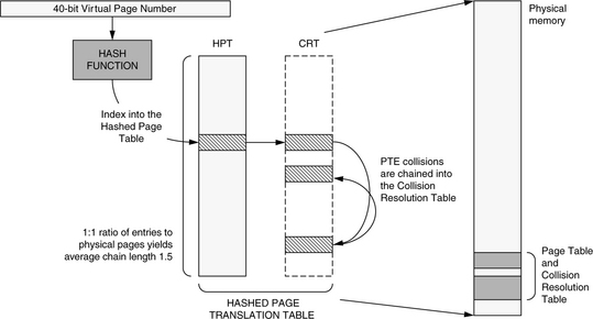
This lookup mechanism is relatively expensive in that it requires at least two memory references to find a PTE; modern inverted tables (e.g., in the PA-RISC and PowerPC architectures) reduce this to one. PA-RISC systems typically use a variant of the inverted page table called the hashed page translation table [Huck & Hays 1993], pictured in Figure 31.7. It is similar to the canonical inverted page table, but it removes the HAT. The table is also unlike the inverted page table in that it can hold more entries than physical pages in the system, and the collision chain can be held in the page table itself or in a separate structure called the collision resolution table. This means that the PFN cannot be deduced from an entry’s location in the hashed page translation table, so each table entry must explicitly record this information: a table entry contains both the VPN and the PFN of the mapped page. The lookup algorithm is simpler than the canonical table’s lookup algorithm, as the initial HAT lookup is gone. The primary difference is that the PFN comes directly from the page table entry itself, not from its location within the table, so the page table entry is a bit larger than the canonical form. The trade-off is space for speed, and the form supports shared memory by allowing multiple mappings to the same physical page to co-exist in the table.
The PowerPC hashed page table is pictured in Figure 31.8 [Weiss & Smith 1994, IBM & Motorola 1993]. It has no HAT, which reduces the minimum number of memory references by one, and the PTE group takes the place of the collision chain. The table is eight PTEs wide, and if more than eight VPNs hash to the same location, the extra PTEs are simply left out. On a TLB miss, the hardware loads an entire PTE group at once and searches through the PTEs for a matching virtual address. This happens even if the PTE group contains no valid PTEs. The PowerPC can perform an optional second lookup to a different PTE group based on a secondary hash value. The second lookup is identical to the first: an entire PTE group is loaded and searched. Each table entry is large—like the PA-RISC table, this is unavoidable because the location of a PTE in the table bears no relation to either the VPN or the PFN in the mapping, and thus both values need to be stored in the PTE. For 32-bit PowerPC implementations, the PTE is 8 bytes wide; for 64-bit implementations, it is 16 bytes wide.

31.1.5 Comparison: Inverted vs. Hierarchical
When a designer implements a virtual memory system on a real-world memory system, subtle problems surface. The choice between hierarchical and inverted page tables is not an obvious one; there are many trade-offs between performance and memory usage. Implementations of shared memory can vary widely in performance, especially with different hardware support. For instance, shared memory on virtual caches requires more consistency management than shared memory on physical caches [Chao et al. 1990], and shared memory’s interactions with different page table organizations can yield significant variations in TLB performance. The address-space protection scheme is also heavily dependent on hardware support and has a great impact on the shared memory implementation.
The first hierarchical tables were accessed top-down. The most common complaint against this design is that its support for large address spaces and sparse address spaces is inefficient. The top-down access variant wastes time because it requires more than two tiers to cover a large address space, and each tier requires a memory reference during table-walking. The bottom-up variant, popularized by the MIPS processor, is more efficient. Although it also may require more than two tiers to map a large address space, the bottom-most tier is probed first, using an easily constructed virtual address. The user PTEs needed for mapping the user address space will likely be found in the cache, often requiring just a single memory reference to cover a TLB miss.
Both access variants can waste memory, because space in the table is allocated by the operating system an entire page at a time. A process-address space with a single page in it will require one full PTE page at the level of the user page table. If the process adds to its address space virtual pages that are contiguous with the first page, they might also be mapped by the existing PTE page, since the PTEs that map the new pages will be contiguous with the first PTE and will likely fit within the first PTE page. If instead the process adds to its address space another page that is distant from the first page, its mapping PTE will be distant from the first PTE and will likely not lie within the first PTE page. A second PTE page will be added to the user page table, doubling the amount of memory required to map the address space. Clearly, if the address space is very sparsely populated—if it is composed of many individual virtual pages spaced far apart—most of the entries in a given PTE page will be unused, but will consume memory nonetheless. Thus, the organization can degrade to using as many PTE pages as there are mapped virtual pages.
The inverted table was developed, in part, to address the potential space problems of hierarchical tables. No matter how sparsely populated the virtual-address space, the inverted page table wastes no memory because the operating system allocates space in the table one PTE at a time. Since the size of the table is proportional to the number of physical pages available in the system, a large virtual address does not affect the number of entries in the table.
However, the inverted organization does have drawbacks. Because the table only contains entries for virtual pages actively occupying physical memory, an alternate structure is required to maintain information for pages on disk in case they are needed again. The organization of this backup page table could potentially negate the space-saving benefit the inverted organization offers. The PowerPC and PA-RISC tables address this issue by removing the size restriction of the table. These organizations may hold more mappings than pages in physical memory, which decreases the pressure on a backup table. Nonetheless, unlike hierarchical tables, these inverted tables cannot guarantee the presence of a desired mapping, and so they do not remove the need for a backup table entirely.
Because the classical inverted table contains one and only one entry for each page frame in the system, it cannot simultaneously hold mappings for different virtual pages mapped to the same physical location. This is pictured in Figure 31.9. If virtual page 1 in Process A’s address space and virtual page 3 in Process B’s address space are mapped to the same page frame, thereby allowing A and B to share memory, both mappings cannot reside in the table at the same time. If the processes are using the memory for communication, the operating system could potentially service two page faults for every message exchange. The PA-RISC and PowerPC variants solve the problem by eliminating the requirement that there exist a one-to-one mapping between PTEs and physical pages in the system.

Like the bottom-up table, inverted tables can be accessed quickly. With a large HAT, each lookup averages just over two memory references. By their elimination of the HAT, the PowerPC and PA-RISC reduce this by one. The technique has mixed results. It reduces the minimum number of memory references by one, but it increases the page table’s size, requiring the PTE to contain both the VPN and the PFN; this increases bandwidth needs and cache needs because fewer PTEs fit in a single cache block than before.
31.1.6 Translation Lookaside Buffers, Revisited
When a process attempts to load from or store to a virtual address, the hardware searches the TLB for the address’s mapping. If the mapping exists in the TLB, the hardware can translate the reference without using the page table. This translation also gives the page’s protection information, which is often used to control access to the on-chip instruction and data caches; this is done instead of maintaining protection information in the cache for each resident block. If the mapping does not exist in the TLB, the hardware does not have immediate access to the protection information, and it conservatively denies the process access to the cache. Even if the data is present in the cache, the process is blocked until the TLB is filled with the correct mapping information.
When placed in this perspective, the TLB is clearly seen to function as a tags array for the main memory cache as well as the actual cache hierarchy fronting main memory. The TLB’s advantage is that, since it is typically situated on-CPU, it has a fast access time. It is therefore also used to map the contents of the on-chip and off-chip processor caches; it provides protection information and performs the function of a tags array for physically indexed caches. However, when used as a tags array for main memory as well as large off-chip caches, its disadvantage is that its reach—notionally, the total memory the TLB can map at once, given by the product of the number of TLB entries and the amount of space each entry maps [Talluri & Hill 1994]—fails to scale with the cache and main memory sizes. While increasing the size of main memory is as simple as buying more DRAM, and increasing the size of an off-chip cache is often just as easy (for a system designer), it is usually not possible to increase the size of the TLB for a given physical CPU chip. Moreover, for reasons of power dissipation, TLB sizes have not increased dramatically over the previous decade, whereas cache and main memory sizes have: the MIPS R2000 TLB in 1990 held 64 entries, compared with the Intel Core processor of 2006, which has 256 entries (128 in each of the I- and D-TLBs). This represents a factor of four increase. In contrast, modern workstations routinely have several megabytes of L2 or L3 cache and one or more gigabytes of DRAM, both of which are two to three orders of magnitude larger than the typical sizes in the early 1990s.
The fact that the TLB reach is effectively decreasing as time goes on is a problem, but it is a problem that could be addressed by exploring unorthodox system organizations and architectures. The page table can require from 0.1 to 10% of main memory [Talluri et al. 1995]. Note that this figure does not include the information required to map those pages held on disk at the moment; it is simply the size of that portion of the page table currently mapping main memory. This amount of main memory is reserved for the page tables and cannot be used for general-purpose data. It is essentially the tags array portion of the main memory cache (which is itself cached by the TLB). An organization potentially just as effective as this could instead use that memory as an explicit hardware tags array. This would accomplish the same purpose: it would map the data array portion of the main memory cache. The advantage would be a potentially simpler and faster addressing scheme, which would reduce the performance cost of taking a TLB miss. The disadvantage would be a potentially higher degree of contention for space in main memory if main memory did not remain fully associative, but, in the age of cheap memory, this can be offset by simply increasing the amount of DRAM, assuming that the resulting power dissipation problems can be solved.
Either the operating system or the hardware can refill the TLB when a TLB miss occurs. With a hardware-managed TLB, a hardware state machine walks the page table; there is no interrupt or interaction with the instruction cache. With a software-managed TLB, the general interrupt mechanism invokes a software TLB-miss handler—a primitive in the operating system usually 10–100 instructions long. If the handler code is not in the instruction cache at the time of the TLB miss exception, the time to handle the miss can be much longer than in the hardware-walked scheme. In addition, the software-managed TLB’s use of the interrupt mechanism adds to the cost by flushing the pipeline, possibly removing many instructions from the reorder buffer; this could amount to hundreds of cycles [Jacob & Mudge 1998c]. However, the software-managed TLB design allows the operating system to choose any organization for the page table, while the hardware-managed scheme defines a page table organization for the operating system. The flexibility afforded by the software-managed scheme can outweigh the potentially higher per-miss cost of the design [Nagle et al. 1994].
Software-managed TLBs are found in MIPS, SPARC, Alpha, and PA-RISC architectures. PowerPC and ×86 architectures use hardware-managed TLBs. The PA-7200 uses a hybrid approach, implementing the initial probe of its hashed page table in hardware [Huck & Hays 1993], and, if this initial probe fails, walking the rest of the page table in software.
If the hardware provides no form of address space protection mechanism (for example, address-space identifiers or segmentation), then the TLB must be flushed on every process context switch. With hardware support for protection, flushing is typically only required when the operating system reassigns an address-space identifier or segment identifier to a new process, such as at process creation or whenever there are fewer address-space identifiers than currently active processes (a scenario that necessitates a temporary ID remapping). Flushing is also required if the protection mechanism goes unused, as is often the case for the segmentation mechanism provided by the ×86 architecture. Generally, one need not empty the entire TLB of its contents; one need only flush those entries tagged with that address-space identifier. However, whereas most instruction sets provide an instruction to invalidate a single TLB entry with a specified VPN and address-space identifier, most do not provide an instruction that invalidates all TLB entries matching an address-space identifier. As a result, the operating system must often invalidate the entire TLB contents or individually invalidate each entry that matches the address-space identifier. Typically, it is cheaper to invalidate the entire TLB contents than to maintain a list of entries to be flushed on context switch, as this list can be large and expensive to maintain.
When one views the entire memory hierarchy as a virtual memory cache for the disk system, new design opportunities become apparent that can exploit the advantages of virtual caches in different ways. For instance, one can have a memory hierarchy that is entirely physically addressed (as is the case with many older architectures such as the VAX and × 86), one can have a memory hierarchy that is partially physically addressed and partially virtually addressed (as is the case with virtually indexed cache systems of today), or one can have a memory hierarchy that is entirely virtually addressed. These organizations are pictured in Figure 31.10. The only conceptual difference between the designs is the point at which the address translation is performed. One must translate addresses before the point at which the hierarchy becomes physically addressed. If most of the hierarchy is physically addressed (e.g., the MIPS R3000 had a physically addressed L1 processor cache, and all subsequent levels in the hierarchy including any L2 cache and physical memory would be addressed physically as well), translation will be required frequently, perhaps on every memory reference, and thus, it is necessary that the act of translating incur a low overhead. If the translation point is moved downward in the hierarchy (toward the backing store), more of the hierarchy is virtually addressed, and the act of translating can be less efficient since it will happen less often, assuming that caches have better global hit rates as one moves further from the processor. It is clear to see that at some point the usefulness of the hardware MMU may decline to where it is actually more trouble than it is worth.

FIGURE 31.10 Possible locations of the translation point. The translation point is the point at which the virtual address must be translated to a physical address to reference a memory location. The point is shown in each diagram by using thick lines to represent the transfer of data between cache level the point moves toward the backing store (which will always require a translation, since the disk subsystem typically uses a different naming scheme from that of main memory or process address spaces), the act of translating can become less efficient since translation will be needed less frequently.
31.1.7 Perspective: Segmented Addressing Solves the Synonym Problem
Earlier chapters have described in some detail the problems that arise when the virtual memory system meets the cache system (see, for example, Chapter 2, Section 2.4, “Virtual Addressing and Protection,” and Chapter 4, Section 4.2, “Consistency with Self”). The traditional purported weakness of virtual caches is their inability to support shared memory. Many implementations of shared memory are at odds with virtual caches. For instance, ASID aliasing and virtual-address aliasing can cause false cache misses and/or give rise to data inconsistencies in a virtual cache, but they are necessary features of many virtual memory implementations. Despite their inherent potential for problems, virtually indexed caches are quite popular due to their speed and power dissipation (no need for a TLB).
By appropriately using a segmented architecture, one can solve these problems and use a virtual cache without significant trouble; the need to flush virtual caches can be eliminated, and virtual cache consistency management can be eliminated. Though it might seem obvious that segmentation can solve the problems of a virtual cache organization, we note that several contemporary microarchitectures use segmented addressing mechanisms, including PA-RISC [Hewlett-Packard 1990], PowerPC [IBM & Motorola 1993], POWER2 [Weiss & Smith 1994], and ×86 [Intel 1993], while only two of the four (PA-RISC and POWER2) take advantage of a virtual cache.
Management of the virtual cache can be avoided entirely if sharing is implemented through the global segmented space. This gives the same benefits as single address space operating systems (SASOS): if virtual-address aliasing (allowing processes to us different virtual addresses for the same physical data) is eliminated, then so is the virtual cache synonym problem. Thus, consistency management of the virtual cache can be eliminated by a simple operating system organization. The advantage of a segmented approach as opposed to a pure SASOS approach is that by mapping virtual addresses to physical addresses in two steps, virtual aliasing and the synonym problem are divided into two orthogonal issues. Thus, applications can map physical memory at multiple locations within their address spaces—they can use virtual-address aliasing, something a SASOS does not support—without creating a synonym problem in the virtual cache.
Segmented Architectures
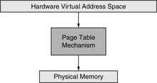
Traditional virtual memory systems provide a mapping between process address spaces and physical memory. SASOS designs place all processes in a single address space and map this large space onto physical memory. Both can be represented as a single level of mapping, as shown in Figure 31.11. These organizations manage a single level of indirection between virtual and physical memory; they combine into a single mechanism the two primary functions of virtual memory: that of providing a virtual operating environment and that of demand-paging on a small (page-sized) granularity. Segmentation allows one to provide these two distinct functions through two distinct mechanisms: two levels of indirection between the virtual-address space and main memory. The first level of indirection supports the virtual operating environment and allows processes to locate objects at arbitrary segment-aligned addresses. The second level of indirection provides movement of data between physical memory and the backing store at the granularity of pages.
This organization is shown in Figure 31.12. Processes operate in the top layer. A process sees a contiguous address space that stretches from 0×00000000 to 0×FFFFFFFF, inclusive (we will restrict ourselves to using 32-bit examples in this report for the purposes of brevity and clarity). The process-address space is transparently mapped onto the middle layer at the granularity of hardware segments, identified by the top bits of the user address. The segments that make up a user-level process may, in actuality, be scattered throughout the global space and may very well not be contiguous. Note that the addresses generated by the process do not reach the cache; they are mapped onto the global space first. The cache and TLB see global addresses only. Therefore, there is no critical path between address generation and a virtual cache lookup except for the segmentation mechanism, and if the segment size is larger than the L1 cache size, the segment bits are not used in the cache lookup. Thus, the segmentation mechanism can run in parallel with the cache access.

Segmented systems have a long history. Multics, one of the earliest segmented operating systems, used a segmented/paged architecture, the GE 645 [Organick 1972]. This architecture is similar to the Intel Pentium memory-management organization [Intel 1993] in that both the GE 645 and the Intel Pentium support segments of variable size. An important point is that the Pentium’s global space is no larger than an individual user-level address space, and there is no mechanism to prevent different segments from overlapping one another in the global 4-GB space.
In contrast, the IBM 801 [Chang & Mergen 1988] introduced a fixed-size segmented architecture that continued through to the POWER and PowerPC architectures [IBM & Motorola 1993, May et al. 1994, Weiss & Smith 1994], shown in Figure 31.13. The PowerPC memory-management design maps user addresses onto a global flat address space much larger than each per-process address space. It is this extended virtual address space that is mapped by the TLBs and page table.
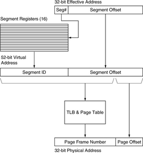
FIGURE 31.13 The PowerPC segmentation mechanism. Segmentation extends a 32-bit user address into a 52-bit global address. The global address can be used to index the caches.
Segmented architectures need not use address-space identifiers; address space protection is guaranteed by the segmentation mechanism.4 If two processes have the same segment identifier, they share that virtual segment by definition. Similarly, if a process has a given segment identifier in several of its segment registers, it has mapped the segment into its address space at multiple locations. The operating system can enforce inter-process protection by disallowing shared segment identifiers, or it can share memory between processes by overlapping segment identifiers.
The “Virtue” of Segmentation
One obvious solution to the synonym and shared memory problems is to use global naming, as in a SASOS implementation, so that every physical address corresponds to exactly one virtual location. This eliminates redundancy of PTEs for any given physical page, with significant performance and space savings. However, it does not allow processes to map objects at multiple locations within their address spaces; all processes must use the same name for the same data, which can create headaches for an operating system, as described earlier in “Perspective on Aliasing.”
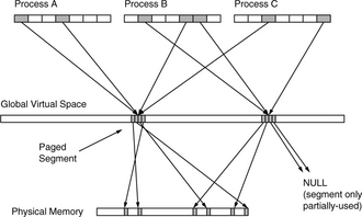
A segmented architecture avoids this problem; segmentation divides virtual aliasing and the synonym problem into two orthogonal issues. A one-to-one mapping from global space to physical space can be maintained—thereby eliminating the synonym problem—while supporting virtual aliases by independently mapping segments in process-address spaces onto segments in the global space. Such an organization is illustrated in Figure 31.14. In the figure, three processes share two different segments and have mapped the segments into arbitrary segment slots. Two of the processes have mapped the same segment at multiple locations in their address spaces. The page table maps the segments onto physical memory at the granularity of pages. If the mapping of global pages to physical pages is one-to-one, there are no virtual cache synonym problems.
When the synonym problem is eliminated, there is no longer a need to flush a virtual cache or a TLB for consistency reasons. The only time flushing is required is when virtual segments are remapped to new physical pages, such as when the operating system runs out of unused segment identifiers and needs to reuse old ones. If there is any data left in the caches or TLB tagged by the old virtual address, data inconsistencies can occur. Direct Memory Access (DMA) also requires flushing of the affected region before a transaction, as an I/O controller does not know whether the data it overwrites is currently in a virtual cache.
The issue becomes one of segment granularity. If segments represent the granularity of sharing and data placement within an address space (but not the granularity of data movement between memory and disk), then segments must be numerous and small. They should still be larger than the L1 cache to keep the critical path between address generation and cache access clear. Therefore, the address space should be divided into a large number of small segments, for instance, 1024 4-MB segments, 4096 1-MB segments, etc.
Disjunct Page Table
Figure 31.15 illustrates an example mechanism. The segmentation granularity is 4 MB. The 4-GB address space is divided into 1024 segments. This simplifies the design and should make the discussion clear. A 4-byte PTE can map a 4-KB page, which can, in turn, map an entire 4-MB segment. The “disjunct” page table organization uses a single global table to map the entire 52-bit segmented virtual-address space yet gives each process-address space its own addressing scope. Any single process is mapped onto 4 GB of this global space, and so it requires 4 MB of the global table at any given moment (this is easily modified to support MIPS-style addressing in which the user process owns only half the 4 GB [Kane & Heinrich 1992]). The page table organization is pictured in Figure 31.16. It shows the global table as a 4-TB linear structure at the top of the global virtual-address space, composed of 230 4-KB PTE pages that each map a 4-MB segment. If each user process has a 4-MB address space, the user space can be mapped by 1024 PTE pages in the global page table. These 1024 PTE pages make up a user page table, a disjunct set of virtual pages at the top of the global address space. These 1024 pages can be mapped by 1024 PTEs—a collective structure small enough to wire down in physical memory for every running process (4 KB, if each is 4 bytes). This structure is termed the per-user root page table in Figure 31.16. In addition, there must be a table for every process containing 1024 segment IDs and per-segment protection information.


Figure 31.17 depicts the algorithm for handling misses in the last-level cache. Processes generate 32-bit effective addresses that are extended to 52 bits by segmentation, replacing the top 4 bits of the effective address. In step 1, the VPN of a 52-bit failing global virtual address becomes an index into the global page table to reference the PTE mapping the failing data (the UPTE), similar to the concatenation of PTEBase and VPN to index into the MIPS user page table. The bottom bits of the address are 0’s, according to the PTE size (e.g., 4 bytes here). The top ten bits of the address are 1’s since the table is at the very top of the global space.
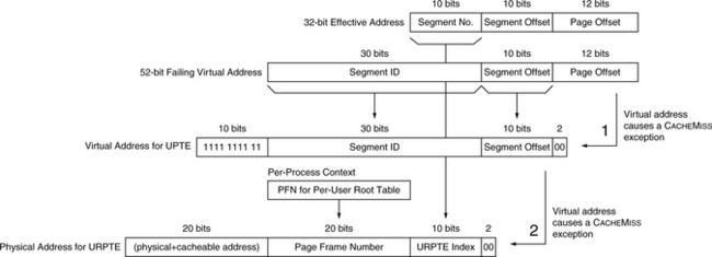
FIGURE 31.17 An example cache-miss algorithm. Step 1 is the result of a user-level L2 cache miss; the operating system builds a virtual address for a PTE in the global page table. If this PTE is not found in the L1 or L2 cache, a root PTE is loaded, shown in step 2. One special requirement is a register holding the initial failing address. Another required hardware structure, the per-process context register, points to the process control block of the active process.
If this reference misses in the L2 cache, the operating system takes a recursive cache-miss exception. At this point, we must locate the mapping PTE in the user root page table. This table is an array of PTEs that cannot be indexed by a global VPN. It mirrors the structure of the user’s perceived address space, not the structure of the global address space, and thus it is indexed by a portion of the original 32-bit effective address. The top 10 bits of the effective address index 1024 PTEs that map a 4-MB user page table, which, in turn, map a 4-GB address space. These 10 bits index the array of 1024 PTEs in the user root page table. In step 2, the operating system builds a physical address for the appropriate PTE in the user root page table (the URPTE), a 52-bit virtual address whose top 20 bits indicate physical+cacheable. It then loads the user root PTE, which maps the user PTE that missed the cache at the end of step 1. When control is returned to the miss handler in step 1, the user PTE load retry will complete successfully.
The page table provides a simple scheme for sharing. Since PTEs in the root page table correspond directly to 4-MB segments in the virtual-address space, two processes need only duplicate information in their root PTEs to share a 4-MB segment. In Figure 31.18, two processes are shown, each with text, data, and stack regions. The two processes share their text regions by duplicating information in their root PTEs (shown in a darker color). This duplication means that one of the PTE pages in the disjunct table overlaps between the two user page tables, enabling the two address spaces to intersect at a 4-MB region.

FIGURE 31.18 Simple sharing mechanism in a hierarchical page table. The structure of the hierarchical page table allows for a simple sharing mechanism, by duplicating information in two or more root page tables. When root PTEs are duplicated, the virtual pages in the user page tables are then mapped to the same physical page and therefore allow two address spaces to overlap. In the figure, two processes are each composed of a text, data and stack region (each less than 4 MB in size), and they share their text regions by sharing a page in their user page tables. Since the text regions are composed of five virtual pages, the shared PTE page contains only five valid PTEs. The shared regions are identical in size (as they must be, since the region is shared), but the other regions (data and stack) need not be and, in the figure, are not.
Processes map objects at arbitrary segment-aligned addresses in their address spaces and can map objects at multiple locations if they wish. Processes can also map objects with different protections, as long as the segmentation mechanism supports protection bits for each segment. As we have described, the global page table maintains a one-to-one mapping between global pages and physical page frames; therefore, the virtual cache synonym problem disappears. The virtual memory fragmentation problem is also solved by this organization. There is no restriction on where an object is placed in the global space, and there is no restriction on where an object is placed in a process-address space.
31.1.8 Perspective: A Taxonomy of Address Space Organizations
Different architectures provide support for operating system features in very different ways. One of the fundamental differences is their treatment of address spaces; it is important to understand the hardware’s view of an address space because the operating system’s mechanisms for shared memory, multi-threading, fine-grained protection, and address space protection are all derived from the hardware’s definition of an address space. This section presents a taxonomy describing the architectural organization and protection of an address space. The Owner portion of the classification characterizes the organization of the hardware address space, and the ID portion characterizes the hardware protection mechanism. The address space available to the application can be owned by a single process or shared among multiple processes. The hardware can provide a single protection identifier per process and page, multiple identifiers per process and/or per page, or no identifiers whatsoever. Table 31.1 describes these characteristics.
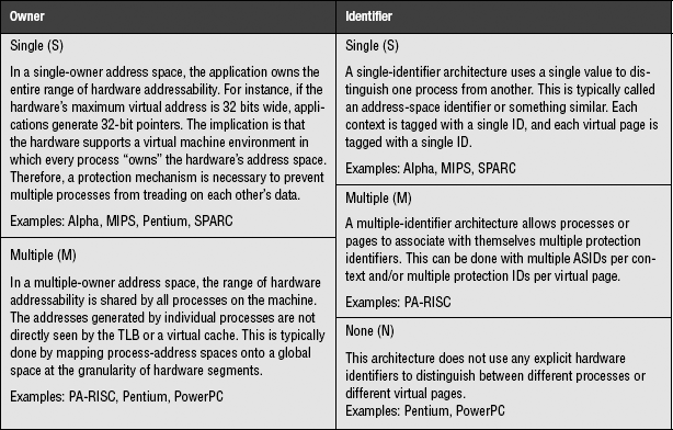
A single-owner space is one in which the entire range of hardware addressability is owned by one process at a time. A single-owner system must provide some sort of protection mechanism (ignoring the use of software protection mechanisms [Wahbe et al. 1993]), or else virtually addressed structures such as the TLB must be flushed on context switch.
A multiple-owner space is divided among many processes. This is not the same as dividing the address space into kernel and user regions as in the MIPS architecture. It instead implies a difference between the addresses generated by processes (private addresses) and the addresses seen by the TLB or virtual caches (global addresses). It is also not the same thing as ASIDs. While it is possible to imagine a global 38-bit address space formed by the concatenation of a 6-bit ASID with a 32-bit per-process virtual address, it is simply an alternate way to look at ASIDs. It is not the same thing as a multiple-owner address space. Figure 31.19 illustrates the difference between the two. An ASID mechanism is useful for protecting address spaces; it is not useful for organizing address spaces.
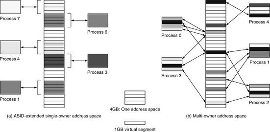
FIGURE 31.19 The difference between ASIDs and a multiple-owner address space. This example compares a 35-bit multiple-owner address space and a 32-bit single-owner address space extended by a 3-bit ASID. In (a) the ASID-extended space is shown. It is organized into eight regions, each of which corresponds to exactly one process as determined by the process ASID. In (b) the multiple-owner space is shown. It is seen as an array of 1-GB virtual segments, each of which can be mapped into any number of process-address spaces, at any location (or multiple locations) within the address space. For example, the second and fourth segments in the address space of Process 0 are mapped to the same virtual segment. Note that the number of processes in scenario (a) is limited by the size of the ASID (case, a limit of eight processes), while there is no limit to the number of processes in scenario (b) unless shared memory is strictly disallowed, in which case the maximum number of processes equals the number of segments (a segment is the minimum size of a process).
The mechanism typically used to provide a multiple-owner address space, hardware segmentation, is also an implicit protection mechanism. A process address space is a set of segments. If the address spaces of two processes have a null intersection, the processes are protected from each other. For example, Process 4 in Figure 31.19(b) has a null intersection with every other address space. Therefore, Process 4 is protected from all other processes, and they are protected from Process 4. When the intersection is non-null, only the segments in the intersection are unprotected. Therefore, further protection mechanisms are, in principle, unnecessary. However, they do become necessary if user-level processes are allowed to modify the contents of the segment registers, which would allow a process to address arbitrary virtual segments.
A single-identifier architecture associates a single protection ID with every process and every page in its address space. This is synonymous with an ASID mechanism, pictured in Figure 31.19(a). Every process is confined to its own virtual address space, and every extended virtual address identifies the address space to which it belongs. The implication is that the only way to share pages is to circumvent the protection mechanism—to make pages globally available by marking them with a special flag that turns off protection on a page-by-page basis. For example, this is seen in the GLOBAL bits of the MIPS and Alpha TLB designs.
A multiple-identifier architecture is designed to support sharing of pages across address spaces by associating more than one ID with every process and/or every page. Therefore, address spaces can belong to multiple protection domains, and pages can belong to multiple process-address spaces. There is no need for a GLOBAL bit mechanism, and the multiple-ID mechanism goes beyond the all-or-nothing sharing of the single-ID mechanism. A multiple-ID mechanism supports finite group ownership, where a shared page can be accessed by a small, well-defined group of processes but not by processes outside the group. Note that we have made the deliberate choice to place segmentation mechanisms into the organization category (owner) and not into the protection category (identifier), though they could be appropriately placed in the latter.
A no identifier architecture provides no hardware protection IDs of any kind. The operating system must provide protection by flushing virtually indexed structures (for example, TLBs and virtually indexed caches) on context switch and/or by using software protection mechanisms.
The various schemes are the following:
• Single-Owner, No ID This architecture makes the entire range of hardware addressability available to the application but does not distinguish between addresses generated by different processes. Therefore, any structure that is dependent on virtual addresses, e.g., the TLB and any virtually addressed cache, must be flushed on context switch. Also, pages must be shared through the page tables; the hardware offers no explicit support for sharing. One possible implementation of the class is shown in Figure 31.20.

• Single-Owner, Single-ID Most microarchitectures today fall into this category. The user-level application generates virtual addresses that, augmented by a single ASID, are used to address all virtual structures, including caches and TLBs. Processes are protected from each other by identifiers, and an entry in a TLB or a line in a cache explicitly identifies its owner. When a process generates an address, the ASID match guarantees that the correct datum is read or written. The disadvantage is that the protection method makes sharing difficult. When all references are tagged with a single owner, the system implicitly requires multiple mappings to the same shared physical page. Intuitively, this reduces the effectiveness of the TLB; Khalidi and Talluri have shown that it doubles the TLB miss rate [1995]. Solutions to this problem have been to subvert the protection mechanism using GLOBAL bits in the TLB, or to vary the structure of the inverted page table, like PA-RISC’s table or the 8-way PTE cache of the PowerPC architecture. One possible implementation of the class is shown in Figure 31.21.

FIGURE 31.21 An implementation of a single-owner, single-ID architecture. The ASID acts as a process ID.
• Single-Owner, Multiple-ID This architecture is not segmented but has multiple protection IDs associated with each process and/or each page. The PA-RISC can be used in this manner. If multiple IDs are associated with each page, each TLB entry could be shared by all the processes with which the page is associated. A TLB entry would have several available slots for protection IDs, requiring more chip area but alleviating the problem of multiple TLB entries per physical page. Alternatively, if there were multiple IDs associated with each process and not with each page (this is like the scheme used in PA-RISC), a different ID could be created for every instance of a shared region, indicating the “identity” of the group that collectively owns the region. One possible implementation of the class is shown in Figure 31.22.

FIGURE 31.22 An implementation of a single-owner, multiple-ID architecture. Each ID in the ID set is compared against every ID in the TLB to find a match. If any match succeeds, the result is a TLB hit.
• Multiple-Owner, No ID This is the basic segmented architecture that maps user addresses onto a global address space at the granularity of segments. This is how the PowerPC architecture is designed, and it is how the Pentium segmentation mechanism can be used. If the Pentium’s 4-GB linear address space were treated as a global space to be shared a segment at a time, the segmentation mechanism would be an effective protection mechanism, obviating the need to flush the TLB on context switch. If the segment registers are protected from modification by user-level processes, no protection identifiers are necessary. One possible implementation of the class is shown in Figure 31.23.

FIGURE 31.23 An implementation of a multiple-owner, no ID architecture. Note that the segment table could be implemented as a direct table-like an SRAM or register file, or it could have tags and be probed for a hit just as a cache is.
• Multiple-Owner, Single-ID This is an extension of the previous architecture by a single protection ID, producing multiple global spaces—each multiple owner, and each protected from each other. Each process would have a window onto a larger multiple-owner address space. There is no reason that a single process would require a unique ID. Several processes could share the same ID and still be protected from each other by the segmentation mechanism. Alternatively, multiple threads within a process could co-exist safely in a single multiple-owner address space, all identified by the same ASID. One possible implementation of the class is shown in Figure 31.24.

FIGURE 31.24 An implementation of a multiple-owner, single-ID architecture. The ASID acts as a process ID. Note that the segment table could be implemented as a direct table like an SRAM or register file, or it could have tags and be probed for a hit just as a cache is.
• Multiple-Owner, Multiple-ID The PA-RISC is an example of this architecture. It defines a global shared virtual-address space and multiple protection IDs as well. In the case of the PA-RISC, the protection IDs are necessary because the PA-RISC segmentation mechanism (space registers) allows a user-level process to modify segment registers and organize its own address space. One could also use this mechanism with secure segmentation, supporting a hierarchy of address spaces with each process-address space mapped onto a global address space, of which many would exist simultaneously. This could be used for maintaining process hierarchies and/or supporting many threads within large address spaces. The difference between this and the previous architecture is that this allows each process-address space to span many different global address spaces at once. One possible implementation of the class is shown in Figure 31.25.
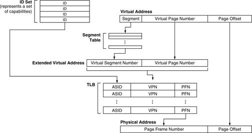
FIGURE 31.25 An implementation of a multiple-owner, multiple-ID architecture. Each ID in the ID set is compared against every ID in the TLB to find a match. If any match succeeds, the result is a TLB hit. Note that the segment table could be implemented as a direct table like an SRAM or register file, or it could have tags and be probed for a hit just as a cache is.
31.2 Implementing Virtual Memory
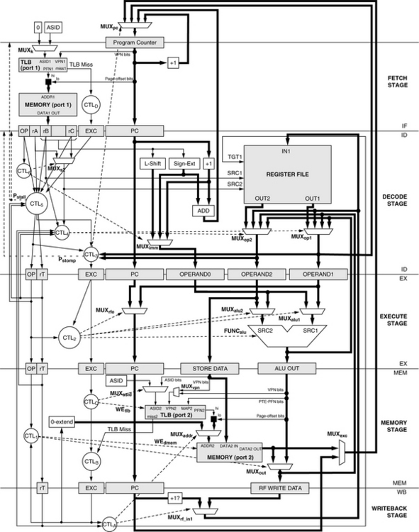
A system’s interrupt mechanism, memory map, and page table/TLB combination comprise the heart of a typical virtual memory system, one of the most fundamental services that a modern operating system provides. Any in-depth look at these facilities exposes the interaction between operating-system-level software and specialized control hardware (e.g., control registers and TLBs, as opposed to instruction-execution hardware) and, in particular, highlights the operating system’s use of and response to precise interrupts, arguably the fundamental building block of today’s multi-tasking systems. This section presents a definition for a base in-order pipeline and then adds support for nested interrupts and virtual memory management via a MIPS-like memory map, page table, and TLB. This example has been used at the University of Maryland since Fall 2000 to teach precise interrupts and operating-system interactions. The instruction set itself is largely immaterial to the discussion (the pipeline organization is compatible with nearly any instruction set), and the interested reader is directed to our on-line companion document for details not covered in the chapter.
The implementation illustrates the operating system’s perspective of the memory system, which is unique because the operating system must use both physical and virtual addresses to reference the memory system. We will see that even an extremely simple example such as this requires a complex and carefully orchestrated arrangement of data structures in memory, values in hardware registers, pipeline extensions, and supporting details in the instruction set that tie everything together.
31.2.1 The Basic In-Order Pipe
The basic RiSC-165 in-order pipeline is shown in Figure 31.26. It is very similar to the five-stage DLX/MIPS pipeline described in both Hennessy and Patterson and Patterson and Hennessy. Though the pipeline is largely independent of instruction-set details, a few ISA-specific details remain:

• The example pipeline supports zero-, one-, two-, and three-operand instructions, including those with immediate values.
• The base three-operand instruction format is shown below. If an instruction writes to the register file, rA identifies the target register. Instructions that do not write to the register file (e.g., store instructions) can use the rA field to denote a read operand (thus, MUXs2).
![]()
• The architecture is word-addressed, not byte-addressed, thus the ‘+1’ in the PC-update path and not ‘+2.’
• Like MIPS/DLX, register 0 is read as zero and non-writable. Thus, a write enable control signal for the register file is implicit in the register specifier in the write-back stage.
In Figure 31.26, shaded boxes represent clocked storage (e.g., registers), thick lines represent word-width busses, thin lines represent smaller datapaths; and dotted lines represent control paths. The pipeline register contents, control logic, and control signals are presented in detail in the on-line companion document. The salient points for this discussion center on the handling of control-flow changes. In particular, on detecting a jump instruction or a mispredicted branch instruction, the ID stage sets a “stomp” signal such that the instruction currently being fetched will not be latched in the IF/ID register (i.e., it will be stomped upon), and the IF/ID register will instead latch a NOP instruction.
The problem to solve is that of providing precise interrupts6 which, as mentioned, are the cornerstone of many operating-system facilities such as multi-tasking and address space protection. A precise interrupt guarantees a clean boundary between those instructions that have completely finished execution and those that have effectively not even started. Having a precise interrupt allows an operating system to halt execution in the middle of a program, do something else, and cleanly return to the point where execution was left off. The only information required to restart program execution is the machine state (i.e., register file contents) and an indication of which instruction is next-to-execute (i.e., a return address).
The difficulty in implementing precise interrupts is to guarantee that no instruction following an “exceptional” instruction can modify permanent state. Caches are effectively permanent state: without hardware support such as speculative-dirty bits per cache block, it is difficult to un-write data that has been written to cache, and all data written to cache is ultimately supposed to find its way to main memory. Out-of-order machines solve the problem by exploiting the reorder buffer [Smith & Pleszkun 1985, 1988], a mechanism designed specifically for the purpose. In-order machines solve the problem by monitoring the state of the pipeline and disallowing memory access when exceptions are observed.
Interrupts are handled at the time of instruction commit. This requires recognizing that an exceptional situation has occurred, holding that information with the instruction state (i.e., in the pipeline registers), propagating the information down the pipeline with the instruction, and acting on it during the write-back stage—and only in the write-back stage. This addresses the case of back-to-back instructions causing exceptions out of order with respect to one another in different stages of the pipeline (e.g., a load instruction that generates an invalid-address exception followed by an instruction with an invalid opcode). This is illustrated in the figure below. If an exceptional instruction is flagged as such at the moment the exception is detected, it is safe to handle that exceptional condition during write-back, because all previous instructions by that time have finished execution and committed their state to the machine.

31.2.2 Precise Interrupts in Pipelined Computers
This section builds upon the previous section and presents a full working pipeline implementation.
Pipeline Modifications
A RiSC-16 pipeline that handles interrupts and exceptions precisely is shown in Figure 31.27. Note that a solid square represents concatenation in the figure. The pipeline diagram reflects the following visible modifications:
1. Support for detecting and handling exceptions and interrupts has been added by the creation of an exception register (labeled EXC in the figure) in pipeline registers IF/ID through MEM/WB. Also, the instruction’s PC is maintained all the way to the MEM/WB register. If a stage’s incoming EXC register is non-zero, the corresponding instruction is interpreted as having caused an exception. The pipeline uses these values to ensure that all instructions following an exceptional instruction become NOPs: if there is an exception in the write-back stage, all other instructions in the pipe should be squashed. If a stage detects a non-zero EXC value, the associated instruction is disabled (its corresponding OP value is turned into something without side effects, like ADD, and its target register rT is set to be non-writable).
2. TLB access has been added to instruction-fetch and data access stages. The choice of a single TLB versus split I- and D-TLBs does not affect the substance of the implementation. Note, however, that the write-back stage must be able to distinguish between an I-TLB miss and a D-TLB miss for purposes of generating the PTE address (this is similar to the MIPS mechanism [Kane & Heinrich 1992] and is described later). This can be done with a 16-bit register in MEMWB to hold the faulting address (which holds either EXMEM.aluout if the D-TLB causes a miss or EXMEM.pc otherwise) or a simple status bit in MEMWB which would be set similarly.
Each pipeline stage must suspend normal operation if its instruction has caused an exception and the pipeline stage modifies machine state (for example, the memory stage must not write to memory if the instruction caused a privilege violation in a previous stage). Each stage must forward the incoming exception code on to the following pipeline stage if it is a nonzero code. If the instruction has not already caused an exception, but does so during the stage in question, the EXC field in the following pipeline register must be set appropriately. Finally, any stage must suspend normal operation if there is an exceptional instruction in the write-back stage, and if “normal” operation can modify state. For example, if the MEMWB.exc register is non-zero, indicating an exceptional instruction in the write-back stage, the memory stage must not allow read or write access to the memory system by the instruction in the memory stage. Otherwise, pipeline operation is as normal. In the simplest form of an exceptional condition, when an exceptional instruction reaches the write-back stage, the following steps are performed by the hardware:
1. Either the PC of the exceptional instruction or the PC of the instruction after the exceptional instruction (PC+1) is saved in a safe place, for instance, a control register built for just such a purpose, typically called something like the exceptional PC (EPC) register. The choice of which value to save is based on the opcode of the exceptional instruction and the type of exception raised: some exception-raising instructions should be retried at the end of a handler’s execution (e.g., a load or store instruction that causes a TLB miss), while others should be jumped over (e.g., TRAP instructions that invoke the operating system—jumping back to a TRAP instruction would simply re-invoke the trap and would cause an endless loop). If the exceptional instruction should be retried, the handler returns to PC; if the exceptional instruction should not be re-executed or retried, the handler returns to PC + 1.
2. The exception type is used as an index into the interrupt vector table (IVT), located at a known physical address, and the vector corresponding to the exception type is loaded into the program counter. This is known as vectoring to the exception/interrupt handler.
3. Some exceptions cause the hardware to perform additional steps before vectoring to the handler. For instance, when handling a TLB-miss exception, before vectoring to the handler, the hardware might create an address for the handler to use in searching the page table. Most architectures that use software-managed TLBs provide such a feature, and ours is described in detail later.
The general form of an exception/interrupt handler, a short piece of software deep in the operating system, looks like the following (note that, in this architecture, hardware places the machine into a privileged operating mode and saves the previous operating mode):
1. Save the EPC in a safe location. This is done in case another exception or interrupt occurs before the handler has completed execution, which would cause the EPC register to be overwritten.
2. Handle the exception/interrupt.
4. Return the processor to the previous operating mode, e.g., user or privileged, and jump to the EPC.
Most architectures have a facility (“return-from-exception,” or similar name) that performs step 4 in an atomic manner.
System-Level Instruction-Set Extensions
To do this, we need the system-level facilities found in microarchitectures that support operating systems and privileged mode. We must protect the operating system from user processes; we must distinguish between processes; we must translate virtual addresses; we need an exception-handling facility; the operating system needs some control registers and would do well to have a set of general-purpose registers that it can use without disturbing user processes (otherwise, it would have to save/restore the entire register state on every exception, interrupt, or trap); etc. Briefly, the extensions to the base pipeline include the following:
• Addition of a privileged kernel mode that is activated upon handling an exception or interrupt or upon handling a TRAP instruction, which raises an exception.
• Addition of a TLB to translate addresses. The TLB should have the same number of ports as the number of memory ports: i.e., if there is a separate instruction-fetch port that is distinct from the data read/write port, then there should be two TLB ports. The trade-off is cost for speed. Fewer ports in both the TLB and memory access translates to a less expensive implementation, but it can also translate to a significant overhead in time spent waiting for a port to free up. Clearly, this choice would be made through an architectural design study.
• The ability for software to enter an exceptional state directly, for example, via trap instructions. Note some “exceptions” that hardware supports are actually privileged instructions that the machine handles at the time of instruction execution, instead of vectoring to a software handler routine. This includes TLB handling routines, mode instructions (e.g., sleep, doze), etc. Table 31.2 gives examples of both instructions (“sys”) and system-level instructions such as TLB-write and return-from-exception.

• Addition of control registers available in privileged mode, e.g., those shown in Figure 31.28. “GPR” refers to a general-purpose register, of which there may be several. The processor status register (PSR) contains mode bits that directly influence processor operation. The interrupt service register (ISR) indicates interrupts that have been received by the processor. The interrupt mask register (IMR) allows software to ignore selected interrupts. The exceptional program counter (EPC) register is filled by hardware when vectoring to a handler and indicates the return address for the exceptional instruction. Even if using a shadow register file of the same size as the user-visible register file while in kernel mode, access to the GPR file may still be possible through special register-move instructions.

• The definition of a memory map that delineates portions of the virtual space as being mapped through the TLBs, accessible in kernel mode only, etc. This is also illustrated in Figure 31.28; the illustrated map resembles both MIPS and VMS architectures. For the example architecture, in user mode all of the address space is mapped through the TLB. All virtual addresses are first translated by the TLB before being used to reference memory locations. Note that this implies that all virtual addresses are valid in user mode. This is similar to VMS, but unlike many other operating systems. In kernel mode, the top half of the address space is mapped through the TLB, and the bottom half is not. This means that addresses in this region, while the computer is in privileged kernel mode, will be sent directly to the memory system without first being translated. This is MIPS-like in design.
• Addition of the concept of an address-space identifier. The ASID distinguishes different processes that run on the machine, and its use allows state from many different processes to reside in the TLB and cache at the same time (otherwise, the TLB and potentially the cache as well would have to be flushed on context switches). In this architecture, ASID 0 is interpreted by the hardware to indicate the kernel executing in privileged mode. When the processor is in kernel mode (i.e., when the K bit in the processor status register is set), instruction fetch must use ASID 0; this overrides whatever value may be in the ASID portion of the processor status register. In contrast, data memory access in the memory stage will use whatever ASID is in the PSR. This last mechanism allows the operating system to read and write locations within different user address spaces (i.e., “masquerade” as different processes), but it prevents the operating system from executing instructions belonging to unprivileged processes, which might otherwise constitute a security hole.
• Creation of memory-management constructs including the user page table organization. Having hardware define this structure is beneficial in that the hardware can quickly generate the address that the TLB-miss handler needs to locate the PTE. Though this could limit flexibility by having the hardware dictate a page table format to the operating system, software can always ignore this address (treat it as a “hint” that need not be followed) to implement whatever page table it wants. However, it would then have to generate its own PTE addresses.
Exceptions and Interrupts
Following Motorola’s terminology, we will distinguish two classes of exceptional conditions: those stemming from internal actions (exceptions) and those stemming from external actions (interrupts). Another type of exception (another class of internally generated exceptional condition) is a trap or syscall. Trap instructions implement various operating system routines, because the trap type is interpreted by the hardware to indicate a particular vector, just like each exception and interrupt type has a separate vector. Each of the trap vectors is operating-system defined (e.g., TRAP 1 can mean read or write or open or close …); the hardware simply vectors to the corresponding handler, so the operating system can attach arbitrary semantics to each of the trap handlers. Most architectures implement only one vector: all system calls are vectored through the same exception, and the user code first places the trap type into a user-visible register or known memory location for the operating system to read once the handler runs. The most noticeable effect of offering more than one trap vector is to reduce the register file pressure in handling system calls, which may be important in architectures with small instruction footprints and thus small register files. Table 31.3 describes various exception codes and/or privileged instructions that one could implement.
TABLE 31.3
Example values targeting the EXC registers in the modified RiSC-16 pipeline
| Code/Instruction | Semantics |
| MODE_RUN | Normal mode—ignore (equivalent to JALR) |
| MODE_SLEEP | Low-power doze mode, awakened by interrupt |
| MODE_HALT | Halt machine (useful for simulators) |
| TLB_READ | Probe TLB for PTE matching VPN in rB |
| TLB_WRITE | Write contents of rB to TLB (random) |
| TLB_CLEAR | Clear contents of TLB |
| MOVE_SPECIAL | Moves a value to/from the control registers from/to the general-purpose registers |
| SYS_RFE | Return From Exception: JUMP (without link) to address held in rB (a control register), and right-shift (zero-fill) the kmode history vector |
| EXC_GENERAL | General exception vector |
| EXC_TLBUMISS | User address caused TLB miss |
| EXC_TLBKMISS | Kernel address caused TLB miss |
| EXC_INVALIDOPCODE | Opcode the execute stage does not recognize |
| EXC_INVALIDADDR | Memory address is out of valid range |
| EXC_PRIVILEGES | Decoded privileged instruction in user mode |
| INT_IO | General I/O interrupt |
| INT_CLOCK | Used to synchronize with external real-time clock |
| INT_TIMER | Raised by a watchdog timer |
| TRAP_GENERAL | General operating system TRAP vector |
| TRAP_1 | OS-definable TRAP vector |
| TRAP_2 | OS-definable TRAP vector |
| … | … |
Control Registers, Generally
The control registers are those extra registers that are visible only in kernel mode:
cr3 - For general-purpose use and TLB interface
cr4 - Processor Status Register
These additional registers perform two separate functions. First, they provide the operating system access to mode-control information such as the PSR and ISR; facilities similar to these are found in nearly every processor architecture in existence and are necessary for most system-level software. The second function served is a small set of shadow registers not visible to user-level processes. While not necessary for implementing most system-level software, shadow registers—such as those found in processors as diverse as the Alpha, SPARC, PA-RISC, Xscale, and M-CORE architectures—provide the operating system a safe haven in which to operate. These registers do not need to be saved when moving to and from privileged mode, as would be necessary if the operating system shared the same register file as user-level code. For instance, the MIPS R2000 architecture has only one space of registers, and the kernel, to avoid having to save and restore user-level registers, claims two of the registers as its own; the assembler and compiler assure that user-level code does not access these registers, and they are not saved or restored on interrupts or system calls and traps. The disadvantage of having shadow registers is either ensuring that data can be moved between the two sets of registers (e.g., by providing a larger register specifier in some or all privileged-mode instructions, or by providing a special data-move operation whose sole function is to move data between register namespaces) or ensuring that such a scenario is never needed.
In the RiSC-16 architecture, cr0–cr7 are the default registers when kernel mode is active, i.e., when the K-mode bit in the processor status register contains a ‘1’ value. Thus, when the operating system performs instructions like the following:
the operand values are read from control registers. The result is written to a control register. This example moves the contents of the processor status register into cr1.
Processor Status Register
The PSR is the heart of a machine, as it contains some of the most important state information in a processor. See Figure 31.28 for a relatively minimal example PSR. It includes three pieces of information: (1) the ASID of the executing process, (2) the kernel-mode bit that enables the privileged kernel mode, and (3) a bit array that represents a history of previous kernel-mode bit values.
1. The address-space identifier (ASID) identifies the process currently active on the CPU. This is used to extend the virtual address when accessing the TLB (see Section 31.1.8 for more details on how address-space identifiers work).
2. The K (kernel-mode) bit indicates whether the processor is in privileged mode or user mode. Privileged instructions are only allowed to execute while the processor is in privileged mode. They cause an exception otherwise (EXC_PRIVILEGES).
3. The K1 through Ki bits make up a shift register that maintains the previous i modes of operation; every time an exception or interrupt is handled, the kernel mode bit is left-shifted into this array (which is itself shifted to the left to accommodate the incoming bit), and the kernel mode is set appropriately (usually turned on). Every invocation of the return-from-exception instruction right-shifts the bit array (while zero-filling from the left) and places the rightmost bit of the array into the kernel-mode bit. To simplify operating system software, this sub-array should be available as read-only to the kernel.
This implementation of maintaining previous history bits allows the hardware to handle nested interrupts, a facility that is extremely important in modern processors and operating systems. A nested interrupt is a situation where the hardware handles an exception or interrupt while in the middle of handling a completely different exception or interrupt. In our implementation of virtual memory, the ability to handle nested interrupts will be of crucial importance.
Concrete Example: RiSC-16 TLB and Page Table Organization
The RiSC-16 is a 16-bit, word-addressed architecture. The page size is 256 bytes; the 64-bit space is divided into 256 pages; and a 16-bit address is divided into an 8-bit page number and an 8-bit page offset. This is a simple architecture, and it serves as a good example largely because very little appears in the literature describing how virtual memory can be done in short-word embedded architectures, even though virtual memory use in these architectures is becoming increasingly popular.
The RiSC-16 architecture uses a software-managed TLB, which simply means that the operating system, and not the hardware, is responsible for handling TLB refill, the act of walking the page table on a TLB miss to find the appropriate PTE and inserting it into the TLB. When the TLB fails to find a given VPN for a mappable virtual address, the TLB raises an exception, invoking the operating system. If the address being translated is a user address (i.e., if the CPU was in user mode at the time of the exception), then the exception raised is a “user miss,” i.e., EXC_TLBUMISS. If the CPU is in kernel mode, and the top bit of the virtual address to be translated is a ‘1,’ then a “kernel miss,” or EXC_TLBKMISS, is raised. If in kernel mode, and the top bit of the address is ‘0,’ the address cannot cause an exception because it is not translated through the TLB, but instead is mapped directly onto physical memory.
The page table format is very similar to that used in the MIPS architecture and is illustrated in Figure 31.29 (note the difference in scale between the user page table and the user address space). The full address space contains 256 pages, which requires 256 PTEs to map it. Each PTE is a single word, and 256 PTEs can thus fit in a single page. Therefore, a single page of PTEs can map the entire user space. The kernel keeps a set of pages in its virtual space, each of which holds one user page table. There are 64 of these tables (there are 64 unique ASIDs; the ASID is 6 bits wide), and the corresponding user tables are held in the top 64 virtual pages of the kernel’s address space. These are, in turn, mapped by root PTEs that are held in the top 64 words of page frame 0. Thus, the VPN of the user page table is equal to the physical address of the root PTE that maps it.
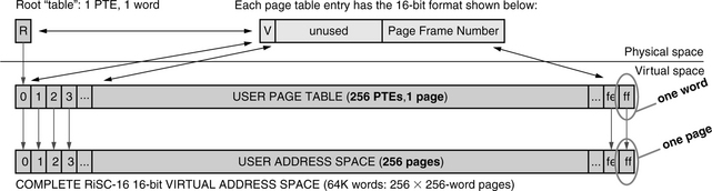
The kernel’s use of the virtual space is shown in Figure 31.30; the top quarter of the address space is dedicated to the user page tables. The ASID is 6 bits, and thus there are 64 tables, each one page in size. When the TLBUMISS exception handler runs, its job is to find the user PTE corresponding to the page that missed the TLB. The (virtual) location of the PTE, given the ASID of the current user process and the VPN of the address that caused the TLB miss, is computed as follows:
ADDRpte = 0 × C000 + (ASID ![]() 8) + VPN
8) + VPN
To aid in the handling of the exception, the construction of this address is performed by hardware. This is similar to the memory-management facilities offered by MIPS and UltraSPARC processors. Because all of the values in question (number of unique ASID values, number of unique VPNs) are powers of two, the additions in the equation above become ordinary concatenations of bit-fields, illustrated on the left half (the User Mode to UMISS transition) of Figure 31.31, which shows the locations in the register file and formats of the various data that are placed into the register file by hardware when vectoring to a TLB-miss handler. At this time, the address is placed into cr3, control register 3. In addition, the return address (EPC) is saved in cr7. Afterwards, the hardware vectors to the UMISS handler. When the handler runs, it will use the virtual address in cr3 to reference the PTE. When the PTE is loaded (the format is shown at the top of Figure 31.29), the handler obtains the PFN. The handler then performs a tlbw (TLB-write) instruction to move the loaded mapping into the TLB.


FIGURE 31.31 Hardware steps in the nested TLB-miss exceptions. In the RiSC-16, like in many architectures that use software-managed TLBs, hardware provides to the operating system not only the address of the faulting instruction (EPC), but the addresses of the faulting user-level and root-level PTEs as well. Upon vectoring to a UMISS or KMISS handler, the hardware places the EPC into control register 7 and the address of the faulting PTE in control register 3. Note that providing the PTE addresses assumes a certain page table organization as well as virtual and physical memory maps (location in virtual space of the user-level page table; location in physical space of the root-level table). The operating system is free to use this information or disregard it and use a different table organization.
Note that the handler loads the PTE into the processor using a virtual address. Thus, it is possible for the handler itself to cause a TLB miss. This invokes the KMISS handler. When handling a kernel-level TLB miss, the page table needed is the kernel’s own page table that maps the top half of the address space (the kernel’s virtual space). This page table is 128 PTEs in length, as it maps 128 pages; it is located at address 128 in physical memory and extends to address 255. This is shown in Figure 31.32. The top half of this page table (addresses 192–255) maps the user page tables referenced by the user TLB-miss handler. By construct, because the user page tables begin at virtual address 0×C000, their VPNs range from 0×C0 to 0×FF—in decimal, the range is 192–255. Therefore, by construction, the VPN of the virtual address for the user PTE that the UMISS handler loads equals the physical address of the kernel PTE that maps the user page table. Before vectoring to the KMISS handler, the hardware places this VPN (which, as described, is equal to the physical address required by the KMISS handler) into cr3, control register 3, as well as saving the return address (EPC) in cr7. This is shown on the right half of Figure 31.31 (the UMISS to KMISS transition).

FIGURE 31.32 The first page of physical memory. The first page of physical memory contains important information, such as the interrupt vector table (Ve, Vi, and Vt), the kernel page table that maps the kernel’s 64 pages of virtual space, and the root page table that maps the 64 user page tables (also in virtual space). In this architecture, we have reserved a small kernel save area at the very bottom 64 words of physical space; this provides access to known memory locations through the load/store instructions’ immediate offset (7 sign-extended bits).
Once the desired PTE has been loaded, generating the TLB entry is straightforward: the handler must verify the validity of the PTE and then write it to the TLB. The TLB-write instruction, tlbw, takes three operands:
1. The faulting VPN (the page that caused the TLB miss)
2. The faulting page’s corresponding PFN, i.e., the contents of the PTE just loaded
Note that, by construction of the page table, items #1 and #3 taken together are the same as the address used to load the PTE, which the hardware stored into cr3 at the time of vectoring to the handler. See the value of cr3 in Figure 31.31. Thus, the TLB-write instruction can easily compact the three operands into two register operands:
1. The PTE, loaded into a register by the operating system
2. The ASID and VPN, loaded into a register by the hardware and used by the operating system to load the PTE
When the tlbw instruction executes, hardware takes the appropriate bits from the register operands and ignores all else. TLB update can be accomplished with the following instructions. Assume that the load address is in r2 and the PTE is in r1.

The steps that the UMISS and KMISS handlers go through are very similar. Note that this is not a complete handler. For example, the beginnings of the handlers are missing (in which register contents are saved and the PTE is loaded), the ends of the handlers are missing (in which register contents are restored from memory), and return-from-exception is missing. These details are where the UMISS and KMISS handlers differ.
Page Zero and Interrupt Vector Table
Figure 31.32 illustrates numerous things, among them the layout of physical page 0, a very important page to the operating system. The kernel save area is used to save/restore state during handler execution. The Ve, Vi, and Vt regions contain vector addresses for exceptions, interrupts, and traps, respectively, which are typically numbered to facilitate easy indexing into the array. The kernel page table (KPT) maps the region of memory in which process structures and associated data are held. The root page table (RPT) contains the mappings for the various user page tables that occupy the top quarter of the virtual-address space. It is no accident that the RPT is placed in the top quarter of page frame 0; as mentioned earlier, the result is that the VPN of any kernel virtual address can be used directly as a physical address to obtain the appropriate root-level PTE.

The interrupt vector table, also part of physical page 0 in this architecture, has a simple format: for every exceptional condition that the hardware recognizes (including exceptions, interrupts, and/or traps), there must be an address in the table that points to a handler routine. The RiSC-16 table is located at physical address 80 in memory and has 48 entries (16 exception types, 16 interrupt types, and 16 trap types). The exception codes happen to correspond exactly to their addresses in the table. The table is illustrated in the figure above.
1Even as far back as the mid- to late 1990s, the move to use virtual memory in embedded systems was well underway. For instance, National Semiconductor abandoned several years’ worth of development on their Pentium-class embedded processor largely due to customer dissatisfaction with the processor’s lack of an MMU [Turley 1998a].
2Portions reprinted, with permission, from “Virtual memory: Issues of implementation,” by Bruce Jacob and Trevor Mudge, IEEE Computer, vol. 31, no. 6, pp. 33–43, June 1998. © 1998 IEEE.
3To “wire down” a region of virtual memory is to reserve space for it in physical memory and not allow it to be paged to disk. Thus, the space cannot be used for any other purpose.
4Page-level protection is a different thing entirely. Whereas address space protection is intended to keep processes from accessing each other’s data, page-level protection is intended to protect pages from misuse. For instance, page-level protection keeps processes from writing to text pages by marking them read-only, etc. Page-level protection is typically supported through a TLB, but could be supported on a larger granularity through the segmentation mechanism. However, there is nothing intrinsic to segments that provide page-level protection, whereas address space protection is intrinsic to their nature.
5The 16-bit Ridiculously Simple Computer.
6Notionally, a precise interrupt is one in which a clear line separates instructions that have completely committed state from those that have not affected the system at all. An in-depth treatment is given in papers by Smith and Pleszkun [1985, 1988].