
Management of Cache Consistency
In any memory system of at least moderate complexity, maintaining cache consistency is a non-trivial matter. Cache consistency is loosely defined as follows:
In the presence of a cache, reads and writes behave (to a first order) no differently than if the cache were not there.
The choice of the word consistency in this book is deliberate, despite the confusion that may result within the architecture community (a memory-consistency model is a contract between programmer and memory system, and a cache-coherence scheme is an implementation of a given memory-consistency model; by cache consistency we mean something different). The reasons for the choice include the following:
• We would rather not invent a new term unless it is unavoidable.
• The term “cache consistency” is no longer used in computer architecture. Rather, as mentioned, the terms “cache coherence” and “consistency model” are used.
• The web cache community already uses the term cache consistency, and their definition mirrors ours.
There are three things that lead to cache consistency, all of which are reflections of the fact that a datum must have one value and only one value. If two requests to the same datum at the same time return different values, then the correctness of the memory system is in question. Put another way, the presence of the cache must not alter the correctness of the memory system’s handling of requests. The use of the term correctness is not an accident. There are many situations in which it is contractually correct, though perhaps not intuitively logical, for the memory system to provide different values for the same datum.
To return to the point, the three aspects of cache consistency are (i) that the cache remain consistent with the backing store, (ii) that the cache remain consistent with itself, and (iii) that the cache remain consistent in the presence of multiple requestors of the datum in question—other clients of the same backing store.
• Consistency with Backing Store: A cache’s data must reflect wwhat is in the backing store, and the backing store must reflect what is in the cache to the extent that no request should get the “wrong” data if the two are out of sync.
• Consistency with Self: If a datum is allowed to exist in multiple locations within the cache, no request must be allowed to get the wrong value.
• Consistency with Other Clients: If multiple requestors are in the system (e.g., multiple processors, multiple caches), the presence of the cache must not enable incorrect data to be propagated to anyone.
The remaining sections discuss these three behaviors in more detail.
4.1 Consistency with Backing Store
Whenever a value is written into a cache, there is immediately a synchronization problem: the cache and its backing store have different values for the same datum. If the backing store serves no other caches, the problem is not particularly severe, as the only way that an incorrect value can be propagated is for the cache to lose the written value or forget that it has it. (Note that such a scenario is possible in virtually indexed caches; see Section 4.2.)
In a more general scenario, the backing store can serve multiple caches and requestors, and the synchronization problem must be solved. There are several obvious solutions to the problem:
• Delayed write, driven by the cache
• Delayed write, driven by the backing store or external client
4.1.1 Write-Through
In a write-through policy, every value written to the cache is written to the backing store immediately, thereby minimizing the window of vulnerability. Though it is far from a complete solution to the cache-consistency problem (it does not provide consistency between multiple clients), it provides a reasonable degree of consistency with the backing store. The scheme is simple and yields a system with, at least potentially, the fewest number of “gotchas.”
However, the speed differential between the cache and its backing store is likely to be non-trivial; otherwise, why have the cache in the first place? If the differential is large, then the cost of sending every write to the backing store can overwhelm the system, bringing performance to a halt. The typical solution is to use the mechanisms of caching and pipelining to solve the problem, as shown in Figure 4.1. The speed differential is equalized by inserting a new memory structure into the system: one that is physically part of the cache (i.e., built of the same technology) and thus can handle frequent writes without slowing down the system, but one that is logically considered part of the backing store.
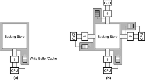
FIGURE 4.1 The use of write buffers and write caches in a write-through policy. (a) The write buffer or write cache is physically part of the cache, but logically part of the backing store. (b) Shows the implication as more caches become clients of the backing store.
The new memory structure is called a write buffer1 if it is a tagless FIFO organization or a write cache if it has tags and can be probed like a cache. Data in the write buffer or write cache is “newer” than the data in the backing store, and therefore it takes precedence over data in the backing store. Data is written to the write buffer/cache immediately, and it is written to the backing store from the write buffer/cache as a background task whenever the channel to the backing store is unused for demand data. Thus, the size of the write buffer/cache is an important consideration; it must be large enough to handle spikes in traffic without overfilling. Overfilling typically requires the structure to be emptied to the backing store, whether it is a convenient time or not.
When handling a request to the backing store, note that all associated write buffers/caches are logically part of the backing store, and therefore they must all be checked for the requested data. In the case of tagless structures (write buffers, as opposed to write caches), there is no way to probe the structure, and therefore its contents must be emptied to memory before the request is handled. Thus, any cache miss results in a write buffer dumping its entire contents to the backing store. Needless to say, this is expensive, and so many systems use tagged buffers, or write caches, which must be emptied to the backing store only when they become overfull.
However, back to the point: on any request to the backing store, all associated write caches must be considered logically part of the backing store, and thus all must be probed for the requested data. This can be avoided to some extent by the use of directories (see the cache-coherence protocols in Section 4.3.2). But, at the very least, the requesting processor usually checks its associated write cache for requested data before sending the request to the backing store.
4.1.2 Delayed Write, Driven By the Cache
This policy delays writing the data to the backing store until later, where “later” is determined by the cache. There are some obvious triggers.
Conflict-Driven Update
In this policy, the data written into the cache is written to the backing store when there is a cache conflict with that block, i.e., data from a written block (i.e., a “dirty” block) is written to the backing store when another block of data is brought into the cache, displacing the dirty block. This is called the writeback policy.
There are some obvious benefits to using a writeback policy. The main things are data coalescing and reduction of write traffic, meaning that oftentimes, an entire block of data will be overwritten, requiring multiple write operations (a cache block is usually much larger than the granularity of data that a load/store instruction handles). Coalescing the write data into a single transfer to the backing store is very beneficial. In addition, studies have found that application behavior is such that writes to one location are frequently followed by more writes to the same location. So, if a location is going to be overwritten multiple times, one should not bother sending anything but the final version to the backing store.
Nonetheless, write-back causes problems in a multi-user scenario (e.g., multiprocessors). Sometimes you will want all of those little writes to the same location to be propagated to the rest of the system so that the other processors can see your activity. One can either return to a write-through policy, or one can create additional update scenarios driven by the backing store, i.e., in the case that the data is needed by someone else. This is discussed briefly in the next section and in more detail in Section 4.3.
Capacity-Driven Update
Note that there exist caches in which the concept of cache conflicts is hazy at best. Many software caches do not implement any organizational structure analogous to cache sets, and waiting to write data to the backing store until the cache is totally full (an event that would be analogous to a cache conflict) may be waiting too late. Such a cache might instead use a capacity-driven update. In this sort of scenario, for example, data could be written to the backing store after a certain threshold amount of data has passed through the cache.
Timer-Driven Update
It should be obvious that cache conflicts or capacity thresholds are not the only trigger events that one might want to have drive data from the cache into the backing store. Another event might be a countdown timer reaching zero: if the goal is to propagate the “final” version of a written datum, the cache could keep track of the time since its last update and write to the backing store once write activity has dropped below a threshold.
Power-Driven Update
An obvious policy is to write data to the backing store when the cost of keeping it in the cache exceeds some threshold. A popular cost metric is power dissipation: if an item is sitting in a solid-state cache, the very act of storing it dissipates power. The transistors dissipate leakage power, and the fact that the data is active means that its tag is checked when the cache is probed (something that applies equally well to software caches).
4.1.3 Delayed Write, Driven by Backing Store
The next obvious policy is for the backing store to decide when the data should be written back. This corresponds to software upcalls, hardware interrupts, coherence messages, etc. The cache holds onto the written data until it can no longer store the data (e.g., for capacity or power dissipation reasons or for other limitations of resources) or until the backing store asks for it.
This is an obvious extension of the write-buffer-write-cache-management policy described earlier, but it is more general than that. In this policy, the backing store serves as the synchronization point for multiple users of data, and it can demand that its client caches update it with the most recent versions of cached, written blocks. The most intuitive use for this is to implement coherence-driven updates (e.g., an incoming request triggers a broadcast or directory-driven request to client caches for the most recent copy of the requested data), but one can also envision other triggers, such as capacity (i.e., the backing store passes a threshold of available free space, particularly applicable to exclusive and non-inclusive caches), timers, or power dissipation.
4.2 Consistency with Self
A cache can run into problems if it allows a particular datum to reside at multiple locations within its structure. This is true of multiprocessor caches, wherein the “cache” can be thought of comprising all processor caches at the same level combined together. It is also true of monolithic caches. We will deal with the multiprocessor cache scenario in the next section; this section focuses on the problem in monolithic caches.
The primary enabler of monolithic caches containing multiple copies of a single datum is naming: to wit, if a datum can have more than one name, and the cache stores data within its extent according to their names, then it is certainly possible for a datum to reside at multiple places within the same cache. Moreover, the primary naming mechanism causing exactly these types of headaches is the virtual memory system and its implementation of shared memory. When these mix with virtual caches, headaches abound. Virtual cache organizations are discussed in “Virtual Addressing and Protection,” Chapter 2, Section 2.4.
4.2.1 Virtual Cache Management
Shared memory causes many headaches for systems designers and developers porting operating systems across microarchitectures. It is beneficial in that it allows two otherwise independent address spaces to overlap at a well-defined intersection, thereby allowing two independent processes to communicate with little to no overhead. However, it also introduces the possibility for a single datum to be placed at multiple locations in a cache, requiring careful cache management to keep data inconsistencies from occurring.
It becomes clear that this feature—shared memory—breaks the cache model of virtual memory. If a single datum is allowed to have several equivalent names, then it is possible for the datum to reside in a cache at multiple locations. This can easily cause inconsistencies, for example, when one writes values to two different locations that map to the same datum. It is for this reason that virtual memory is described as a mapping between two namespaces; one must remember this when dealing with virtual caches. As long as there is a one-to-one mapping between data and names, no inconsistencies can occur, and the entire virtual memory mechanism behaves no differently than a traditional cache hierarchy. Thus, virtual caches can be used without fear of data inconsistencies. As soon as shared memory is introduced, the simple cache model becomes difficult to maintain, because it is very convenient for an operating system to allow one-to-many namespace mappings. However, as we will see in later chapters, there are many tricks one can play to keep the cache model and still support shared memory.
The Consistency Problem of Virtual Caches
A virtually indexed cache allows the processor to use the untranslated virtual address as an index. This removes the TLB from the critical path, allowing shorter cycle times and/or a reduced number of pipeline stages. However, it introduces the possibility of data-consistency problems occurring when two processes write to the same physical location through different virtual addresses; if the pages align differently in the cache, erroneous results can occur. This is called the virtual cache synonym problem [Goodman 1987]. The problem is illustrated in Figure 4.2; a shared physical page maps to different locations in two different process-address spaces. The virtual cache is larger than a page, so the pages map to different locations in the virtual cache. As far as the cache is concerned, these are two different pages, not two different views of the same page. Thus, if the two processes write to the same page at the same time, using two different names, then two different values will be found in the cache.
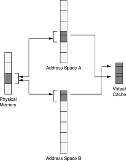
FIGURE 4.2 The synonym problem of virtual caches. If two processes are allowed to map physical pages at arbitrary locations in their virtual-address spaces, inconsistencies can occur in a virtually indexed cache.
Hardware Solutions
The synonym problem has been solved in hardware using schemes such as dual tag sets [Goodman 1987] or back-pointers [Wang et al. 1989], but these require complex hardware and control logic that can impede high clock rates. One can also restrict the size of the cache to the page size or, in the case of set-associative caches, similarly restrict the size of each cache bin (the size of the cache divided by its associativity [Kessler & Hill 1992]) to the size of one page. This is illustrated in Figure 4.3; it is the solution used in many desktop processors such as various PowerPC and Pentium designs. The disadvantages are the limitation in cache size and the increased access time of a set-associative cache. For example, the Pentium and PowerPC architectures must increase associativity to increase the size of their on-chip caches, and both architectures have used 8-way set-associative cache designs. Physically tagged caches guarantee consistency within a single cache set, but this only applies when the virtual synonyms map to the same set.

Software Solutions
Wheeler and Bershad describe a state-machine approach to reduce the number of cache flushes required to guarantee consistency [1992]. The mechanism allows a page to be mapped anywhere in an address space, and the operating system maintains correct behavior with respect to cache aliasing. The aliasing problem can also be solved through policy, as shown in Figure 4.4. For example, the SPUR project disallowed virtual aliases altogether [Hill et al. 1986]. Similarly, OS/2 locates all shared segments at the same address in all processes [Deitel 1990]. This reduces the amount of virtual memory available to each process, whether the process uses the shared segments or not. However, it eliminates the aliasing problem entirely and allows pointers to be shared between address spaces. SunOS requires shared pages to be aligned on cache-size boundaries [Hennessy & Patterson 1990], allowing physical pages to be mapped into address spaces at almost any location, but ensuring that virtual aliases align in the cache. Note that the SunOS scheme only solves the problem for direct-mapped virtual caches or set-associative virtual caches with physical tags; shared data can still exist in two different blocks of the same set in an associative, virtually indexed, virtually tagged cache. Single address space operating systems such as Opal [Chase et al. 1992a, 1992b] or Psyche [Scott et al. 1988] solve the problem by eliminating the concept of individual per-process address spaces entirely. Like OS/2, they define a one-to-one correspondence of virtual to physical addresses and in doing so allow pointers to be freely shared across process boundaries.
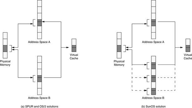
FIGURE 4.4 Synonym problem solved by operating system policy. OS/2 and the operating system for the SPUR processor guarantee the consistency of shared data by mandating that shared segments map into every process at the same virtual location. SunOS guarantees data consistency by aligning shared pages on cache-size boundaries. The bottom few bits of all virtual page numbers mapped to any given physical page will be identical, and the pages will map to the same location in the cache. Note that this works best with a direct-mapped cache.
Combined Solutions
Note that it is possible, using a segmented hardware architecture and an appropriate software organization, to solve the aliasing problem. The discussion is relatively long, so we have placed it in Chapter 31, Section 31.1.7, “Perspective: Segmented Addressing Solves the Synonym Problem.”
An important item to note regarding aliasing and set-associative caches is that set associativity is usually a transparent mechanism (the client is not usually aware of it), and the cache is expected to guarantee that the implementation of set associativity does not break any models. Thus, a set-associative cache cannot use virtual tags unless the set associativity is exposed to the client. If virtual tags are used by the cache, the cache has no way of identifying aliases to the same physical block, and so the cache cannot guarantee that a block will be unique within a set—two different references to the same block, using different virtual addresses, may result in the block being homed in two different blocks within the same set.
Perspective on Aliasing
Virtual-address aliasing is a necessary evil. It is useful, yet it breaks many simple models. Its usefulness outweighs its problems. Therefore, future memory-management systems must continue to support it.
Virtual-Address Aliasing Is Necessary
Most of the software solutions for the virtual cache synonym problem address the consistency problem by limiting the choices where a process can map a physical page in its virtual space. In some cases, the number of choices is reduced to one; the page is mapped at one globally unique location or it is not mapped at all. While disallowing virtual aliases would seem to be a simple and elegant way to solve the virtual-cache-consistency problem, it creates another headache for operating systems—virtual fragmentation.
When a global shared region is garbage-collected, the region cannot help but become fragmented. This is a problem because whereas de-fragmentation (compaction) of disk space or physically addressed memory is as simple as relocating pages or blocks, virtually addressed regions cannot be easily relocated. They are location-dependent; all pointers referencing the locations must also be changed. This is not a trivial task, and it is not clear that it can be done at all. Thus, a system that forces all processes to use the same virtual address for the same physical data will have a fragmented shared region that cannot be de-fragmented without enormous effort. Depending on the amount of sharing, this could mean a monotonically increasing shared region, which would be inimical to a 24 × 7 environment, i.e., one that is intended to be operative 24 hours a day, 7 days a week. Large address SASOS implementations on 64-bit machines avoid this problem by using a global shared region that is so enormous it would take a very long time to become overrun by fragmentation. Other systems [Druschel & Peterson 1993, Garrett et al. 1993] avoid the problem by dividing a fixed-size shared region into uniform sections and/or turning down requests for more shared memory if all sections are in use.
Virtual-Address Aliasing Is Detrimental
There are two issues associated with global addresses. One is that they eliminate virtual synonyms, and the other is that they allow shared pointers. If a system requires global addressing, then shared regions run the risk of fragmentation, but applications are allowed to place self-referential pointers in the shared regions without having to swizzle [Moss 1992] between address spaces. However, as suggested above, this requirement is too rigid; shared memory should be linked into address spaces at any (page-aligned) address, even though allowing virtual aliasing can reduce the ability to store pointers in the shared regions.
Figure 4.5 illustrates the problem: processes A and Z use different names for the shared data, and using each other’s pointers leads to confusion. This problem arises because the operating system was allowed or even instructed by the processes to place the shared region at different virtual addresses within each of the two address spaces. Using different addresses is not problematic until processes attempt to share pointers that reference data within the shared region. In this example, the shared region contains a binary tree that uses self-referential pointers that are not consistent because the shared region is located at different virtual addresses in each address space.
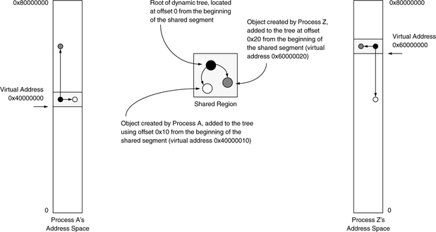
It is clear that unless processes use the same virtual address for the same data, there is little the operating system can do besides swizzle the pointers or force applications to use base+offset addressing schemes in shared regions. Nonetheless, we have come to expect support for virtual aliasing. Therefore, it is a requirement that a system support it.
Virtual Caches and the Protection Problem
A virtual cache allows the TLB to be probed in parallel with the cache access or to be probed only on a cache miss. The TLB traditionally contains page protection information. However, if the TLB probe occurs only on a cache miss, protection bits must be stored in the cache on a per-block basis, or else protection is effectively being ignored. When the protection bits for a page are replicated across several cache lines, changing the page’s protection is non-trivial. Obvious mechanisms include flushing the entire cache on protection modification or sweeping through the cache and modifying the appropriate lines. The operating system changes page protections to implement such features as copy-on-write, to reduce copy overhead when a process forks, or simply to share memory safely between itself and user processes.
A similar problem happens when a process terminates. If the cache is write-back, it is possible for a stale portion of a process’s address space to remain in the cache while the physical page is remapped into a new address space. When the stale portion is written back, it overwrites the data in the new address space. Obvious solutions include invalidating the entire cache or selected portions. These types of problems are often discovered when porting operating systems to architectures with virtual caches, such as putting Mach or Chorus on the PA-RISC.
4.2.2 ASID Management
Described earlier, ASIDs are a non-trivial hardware resource that the operating system must manage on several different levels. To begin with, an operating system can maintain hundreds or thousands of active processes simultaneously, and in the course of an afternoon, it can sweep through many times that amount. Each one of these processes will likely be given a unique identifier, because operating systems typically use 32-bit or 64-bit numbers to identify processes. In contrast, many hardware architectures only recognize tens to hundreds of different processes [Jacob & Mudge 1998b]—MIPS R2000/3000 has a 6-bit ASID; MIPS R10000 has an 8-bit ASID; and Alpha 21164 has a 7-bit ASId. The implication is that there cannot be a one-to-one mapping of process IDs to ASIDs, and therefore an operating system must manage a many-to-many environment. In other words, the operating system will be forced to perform frequent remapping of address-space IDs to process IDs, with TLB and cache flushes required on every remap (though, depending on implementation, these flushes could be specific to the ASID involved and not a whole-scale flush of the entire TLB and/or cache). Architectures that use IBM 801-style segmentation [Chang & Mergen 1988] and/or larger ASIDs tend to have an easier time of this.
ASIDs also complicate shared memory. The use of ASIDs for address space protection makes sharing difficult, requiring multiple page table and TLB entries for different aliases to the same physical page. Khalidi and Talluri describe the problem:
Each alias traditionally requires separate page table and translation lookaside buffer (TLB) entries that contain identical translation information. In systems with many aliases, this results in significant memory demand for storing page tables and unnecessary TLB misses on context switches. [Addressing these problems] reduces the number of user TLB misses by up to 50% in a 256-entry fully-associative TLB and a 4096-entry level-two TLB. The memory used to store hashed page tables is dramatically reduced by requiring a single page table entry instead of separate page table entries for hundreds of aliases to a physical page, [using] 97% less memory. [Khalidi & Talluri 1995]
Since ASIDs identify virtual pages with the processes that own them, mapping information necessarily includes an ASId. However, this ensures that for every shared page there are multiple entries in the page tables, since each differs by at least the ASId. This redundant mapping information requires more space in the page tables, and it floods the TLB with superfluous entries. For instance, if the average number of mappings per page were two, the effective size of the TLB would be cut in half. In fact, Khalidi and Talluri [1995] report the average number of mappings per page on an idle system to be 2.3, and they report a decrease by 50% of TLB misses when the superfluous-PTE problem is eliminated. A scheme that addresses this problem can reduce TLB contention as well as physical memory requirements.
The problem can be solved by a global bit in the TLB entry, which identifies a virtual page as belonging to no ASID in particular; therefore, every ASID will successfully match. This is the MIPS solution to the problem; it reduces the number of TLB entries required to map a shared page to exactly one, but the scheme introduces additional problems. The use of a global bit essentially circumvents the protection mechanism and thus requires flushing the TLB of shared entries on context switch, as the shared regions are otherwise left unprotected. Moreover, it does not allow a shared page to be mapped at different virtual addresses or with different protections. Using a global-bit mechanism is clearly unsuitable for supporting sharing if shared memory is to be used often.
If we eliminate the TLB, then the ASID, or something equivalent to distinguish between different contexts, will be required in the cache line. The use of ASIDs for protection causes the same problem, but in a new setting. Now, if two processes share the same region of data, the data will be tagged by one ASID, and if the wrong process tries to access the data that is in the cache, it will see an apparent cache miss simply because the data is tagged by the ASID of the other process. Again, using a global bit to marked shared cache lines leaves them unprotected against other processes, and so the cache lines must be flushed on context switch. This is potentially much more expensive than flushing mappings from the TLB, because the granularity for flushing the cache is usually a cache line, requiring many operations to flush an entire page.
4.3 Consistency with Other Clients
When the concept of caching is introduced into a multi-client or multiprocessor system, the consistency of the memory system should not change—the mere existence of caches should not change the value returned by a client’s request.
Or, at least, that is the way things started. However, while it is certainly possible to build mechanisms that ensure this happens (to wit, to ensure that a distributed system of caches and memories behaves like a monolithic memory system), and while systems are quite capable of doing it, the performance cost of doing so can be prohibitively expensive as compared to the performance one can get were one to relax the constraints a little. Consequently, different memory-consistency models have been proffered wherein the constraints are progressively relaxed—these are contracts with the memory system that provide looser guarantees on ordering but higher potential performance. In such scenarios, just as in a lossy data network, for example, the programmer can always ensure the desired behavior by using higher level synchronization protocols. For example, in a lossy network (i.e., any realistic network), one can implement a reliable transmission service by creating a handshaking protocol that notifies a sender of a packet’s delivery and generates a retransmission in the event that no acknowledgment arrives within a given time period. Similar mechanisms can be used to make a relaxed consistency model behave like a tighter model for when the programmer needs such guarantees.
4.3.1 Motivation, Explanation, Intuition
To make the concepts more clear, we present the types of problems that can occur, give some intuition for the range of solutions, and then discuss specific implementation details.
Scenario One
Figure 4.6 illustrates an example scenario.
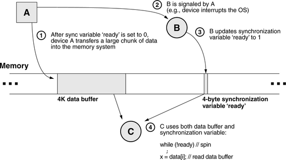
FIGURE 4.6 Race condition example. At time 1, the synchronization variable “ready” is initialized to 0. Meanwhile, hardware device A begins to transfer data into the memory system. When this transfer is complete, A sends B a message, whereupon B updates the synchronization variable. Meanwhile, another software process, C, has been spinning on the synchronization variable ready waiting for it to become non-zero. When it sees the update, it reads the data buffer.
• Hardware device A transfers a block of data into memory (perhaps via a DMA [direct memory access] controller).
• Software process B is A’s controller. It is a user-level process communicating with device A via a control link such as a serial port.
• Software process C is a consumer of the data and waits for B’s signal that the data is ready.
Though the scenario is contrived to have a (potential) race condition buried within it, this general structure is representative of many embedded systems in which software processes interact with hardware devices. The specifics of the scenario are as follows:
1. B communicates to client processes via a synchronization variable called “ready” that indicates when a new block of data is valid in the memory system. At time 1, B sets this variable to the value 0 and initiates the transfer of data from hardware device A to the memory system.
2. When the data transfer is complete, the hardware device signals the controlling software process via some channel such as a device interrupt through the operating system, or perhaps the controlling software must continuously poll the hardware device. Whatever the implementation, process B is aware that the data transfer has finished at time 2.
3. At time 3, B updates the synchronization variable to reflect the state of the data buffer. It sets the variable to the value 1.
4. Meanwhile, process C has been spinning on the synchronization variable, waiting for the data to become available. A simple code block for the client process C could be the following:
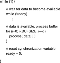
When the synchronization variable indicates that the data is in memory, the client process starts reading it. When it finishes, the process begins again. For example, the server process B could be responsible for initializing the variable ready at the outset, starting up C, and, from then on, B spins on ready to become 0, initiates a new data transfer, sets ready to 1, and spins again—in the steady state, B is responsible only for the 0 -> 1 transition, and C is responsible only for the 1 ->0 transition.
The timing of events is shown in Figure 4.7. In a simple uniprocessor system, the example has very straightforward behavior; the memory system enforces sequentiality of memory references by definition; the single processor enforces sequentiality of task execution by definition; and the only thing that could cause a problem is if the software process that does the transferring of data from A into the memory system (e.g., perhaps a device driver within the operating system) takes too long to transfer the data from its own protected buffer space into the user-readable target buffer.
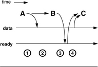
In a simple uniprocessor system, causality is preserved because the system can only do one thing at a time: execute one instruction, handle one memory request. However, once this no longer holds, e.g., if this example is run on a multiprocessor or networked multicomputer, then all bets are off. Say, for example, that the memory system is distributed across many subsystems and that each of the processes (B, C, and the data transfer for A) are each running on a different subsystem. The question arises in such a scenario: does C get the correct data? This is a perfectly reasonable question to ask. Which happens first, the data buffer being available or the synchronization variable being available? In a complex system, the answer is not clear.
An Analogy: Distributed Systems Design
Let’s first explore why arbitrary ordering of memory requests might be a good thing. We have put forth a scenario in which arbitrary ordering in the memory system could create a race condition. This happens because our scenario exhibits a causal relationship between different, seemingly unrelated, memory locations, but note that not all applications do. Moreover, while consistency models exist that make a multiprocessor behave like a uniprocessor, their implementations usually come at the price of lower achievable performance. A better scheme may be to relax one’s expectations of the memory system and instead enforce ordering between events explicitly, when and where one knows causal relationships to exist.
The same concepts apply in network-systems design, and the issues can be more intuitive when couched in network terms. In particular, the following analogy gives implementation details that apply not just to distributed systems, but also to cache-coherence implementations, both hardware and software. Those already familiar with the issues might want to skip ahead, as the analogy is long and intended for readers who have not really thought about the issues of timing and causality in a networked system.
Imagine the development of a distributed system, a set of software processes on a network that provide some function and that use the network for communication to coordinate their behavior. The details of the high-level algorithm (the function that the set of processes provides in their cooperative fashion) do not matter for this discussion. At the outset of the system design, the designer has a wide range of choices to make regarding his assumptions of the network. For instance,
• Is delivery of a message guaranteed? In particular, if a process places a message packet onto the network, does the network guarantee that the intended recipient will receive that packet? Can the recipient receive the packet more than once? Can the network lose the packet? If yes, is any process on the network alerted to the loss?
• Is the delivery time of a message bounded? A network, even if it does not guarantee delivery of a packet, may be able to guarantee that, if the packet is delivered, it will be delivered within a certain window of time; otherwise, the packet will not be delivered even if not lost.
• Is the ordering of messages on the network preserved? If a process places a series of packets on the network, will they be delivered in that same serial order?
Depending on the assumptions of how the network behaves, the developer will choose to code the program very differently.
• If delivery of a message is guaranteed to be 1 (not 0, not 2 or more times), the time is bounded, and the network is guaranteed to preserve the ordering of messages, then the code can look very much like that of a functional programming model written for a sequential processor. In such a scenario, processes can send messages as if they are executing functions, and, in many cases, this is exactly how distributed systems are built from originally monolithic software implementations: by dividing work between processes at the function-call boundary. This is the nature of the remote procedure call (RPC) paradigm. It makes for a very simple programming model, because neither the designer nor the programmer need concern himself with details of the underlying medium.
• What if it is possible for the network to deliver a given message multiple times? For example, what if a packet placed on the network can be delivered to the recipient twice? If such an event would make no difference whatsoever to the functional correctness of the program, then this is not a big deal. However, if it can cause problems (e.g., imagine banking software receiving a credit/debit message for a particular account more than once), then the software must expect such a situation to occur and provide a mechanism to handle it. For example, the software could add to every outgoing packet a message number that is unique2 within the system, and a recipient discards any packet containing a message number that it has already seen.
• What if message ordering is not guaranteed? For example, what if a series of packets sent in a particular order arrive out of order at the destination? If such an event can cause problems, then the software must expect such a situation to occur and provide a mechanism to handle it. For example, the software could build into its message-handling facility a buffering/sequencing mechanism that examines incoming messages, delivering them up to the higher level if the sequence number is consecutive from the last packet received from that sender or buffering (and rearranging) the message until the packet/s with the intervening sequence number/s arrive. If the delivery time of a message is bounded, then the handler need only wait for that threshold of time. If the intervening sequence numbers are not seen by then, the handling software can assume that the sender sent packets with those sequence numbers to different recipients, and thus, there is no gap in the sequence as far as this recipient is concerned (the gap is not an indication of functional incorrectness).
• But what if delivery time is not bounded? Well, then things get a bit more interesting. Note that this is functionally (realistically) equivalent to the case that delivery is not guaranteed, i.e., a packet sent to a destination may or may not reach the destination. As before, if this poses any problem, the software must expect it and handle it. For instance, the recipient, upon detecting a gap in the sequence, could initiate a message to the recipient asking for clarification (i.e., did I miss something?), resulting in a retransmission of the intervening message/s if appropriate. However, the receiver in a distributed system is often a server, and, in general, it is a bad idea to allow servers to get into situations where they are blocking on something else, so this particular problem might best be handled by a sender-/client-side retry mechanism. To wit, build into the message-passing facility an explicit send-acknowledge protocol: every message sent expects a simple acknowledgment message in return from the recipient. If a sender fails to receive an acknowledgment in a timely fashion, the sender assumes that the message failed to reach the destination, and the sender initiates a retry. Separate sequence numbers can be maintained per recipient so that gaps seen by a recipient are an indication of a problem.
A designer always builds into a system explicit mechanisms to handle or counter any nonideal characteristics of the medium.
A designer that assumes the medium to be ideal needs no such mechanisms, and his code can look virtually identical to its form written for a single processor (no network). The less ideal a designer assumes the medium, the more workarounds his program must include.
In Particular, Cache Systems
How does the analogy apply here? It turns out that writing software to deal with a distributed cache system (e.g., a multiprocessor cache system, a web-document proxy cache, etc.) is very much like writing for a network. In particular, the memory-consistency model describes and codifies one’s assumptions of the medium; it describes a designer’s understanding of how the cache and memory systems behave, both independently of each other and interactively. The memory-consistency model represents an understanding of how the memory system will behave, on top of which a designer creates algorithms; it is a contract between programmer and memory system.
It is reasonable to ask why, in the network case, would anyone ever choose to write the complicated software that makes very few assumptions about the behavior of the network. The answer is that such systems always represent trade-offs. In general, there is no free lunch, and complexity will be found somewhere, either in the infrastructure (in the network), in the user of the infrastructure (the distributed-systems software), or somehow spread across the two. The level of guarantee that an infrastructure chooses to provide to its clientele is often a case of diminishing returns: an infrastructure stops providing guarantees once its implementation reaches a level of complexity where the next improvement in service would come at a prohibitive cost. Thus, as an example, the Internet Protocol (IP) provides message delivery, but not reliable message delivery, and in cases where a designer wants or needs reliable message delivery, the facility is built on top of the base infrastructure (e.g., TCP/IP, reliable datagrams, etc).
The same is true in cache systems. It is very simple to write programs for a uniprocessor that has a single cache, and it is enticing to think that it should be no harder to write programs for multiprocessors that have many caches. In fact, many modern multiprocessor cache systems provide exactly that illusion: an extremely simple memory-consistency model and associated cache-coherence mechanism that support the illusion of simplicity by forcing a large number of distributed hardware caches to behave as one.
As one can imagine, such a system, lying as it does at one end of the complexity trade-off continuum, might not give the best performance. Thus, there are many different consistency models from which to choose, each representing a level of service guarantee less stringent than the preceding one, a hardware system that is less costly to build, and the potential for greater performance during those windows of time during which the software does not need the illusion of a single memory port.
The following are some example issues to note about the implementation, once the cache system becomes complex and/or distributed about a network:
• Suppose it is possible for writes to be buffered (not propagated directly to the backing store) and for reads to be satisfied from nearby caches. Such is the case with web proxies or multiprocessor caches. Such a system can have multiple cached copies of a given item, each with a different value, and if no effort is made to reconcile the various different versions with one another, problems can arise.
• Suppose that, in an implementation, the cache’s backing store is not a monolithic entity, but rather a collection of storage structures, each with its own port. This is the case for NUMA multiprocessor organizations, a popular design choice today. If data migration is possible, i.e., if it is possible for a given datum to reside in two places in the distributed backing store, then one can envision scenarios in which two writes to the same datum occur in different orders, depending on which segment of the backing store handles the requests.
• Whatever mechanism is used to ensure consistency between different caches and different users/processors must also be aware of the I/O system, so that I/O requests behave just like “normal” memory requests. The reason for this will become clear in a moment.
Note that this is by no means a complete list of issues. It is just given to put the problem into perspective.
4.3.2 Coherence vs. Consistency
At this point we should formally discuss memory coherence and memory consistency, terms that speak to the ordering behavior of operations on the memory system. We illustrate their definitions within the scope of the race condition example and then discuss them from the perspective of their use in modern multiprocessor systems design.
Memory Coherence: The principle of memory coherence indicates that the memory system behaves rationally. For instance, a value written does not disappear (fail to be read at a later point) unless that value is explicitly overwritten. Write data cannot be buffered indefinitely; any write data must eventually become visible to subsequent reads unless overwritten. Finally, the system must pick an order. If it is decided that write X comes before write Y, then at a later point, the system may not act as if Y came before X.
So, in the race condition example, coherence means that when B updates the variable ready, C will eventually see it. Similarly, C will eventually see the data block written by A. When C updates the variable to 0 at the end of its outer loop, the spin loop immediately following that update [while(!ready)] will read the value 0 until and unless B updates the variable in the meantime.
Memory Consistency: Whereas coherence defines rational behavior, the consistency model indicates how long and in what way/s the system is allowed to behave irrationally with respect to a given set of references. A memory-consistency model indicates how the memory system interleaves read and write accesses, whether they are to the same memory location or not. If two references refer to the same address, their ordering is obviously important. On the other hand, if two references refer to two different addresses, there can be no data dependencies between the two, and it should, in theory, be possible to reorder them as one sees fit. This is how modern DRAM memory controllers operate, for instance. However, as the example in Figure 4.6 shows, though a data dependence may not exist between two variables, a causal dependence may nonetheless exist, and thus it may or may not be safe to reorder the accesses. Therefore, it makes sense to define allowable orderings of references to different addresses.
In the race condition example, depending on one’s consistency model, the simple code fragment
![]()
may or may not work as one expects. If the model allows arbitrary reordering, then the value of the variable ready may be seen by outside observers (i.e., by process C) before the values written to the data buffer become available, in which case C would get the wrong results.
To the newcomer, these terms have arguably unsatisfying definitions. Despite the clear distinction between the two, there is significant overlap when one goes a bit deeper. Many little items demonstrate a significant grey area at the intersection of the concepts of coherence and consistency. For instance,
• The popular definitions of consistency and coherence differentiate the two with the claim that one (coherence) defines the behavior of reads and writes to the same address, while the other (consistency) defines the behavior of reads and writes to different addresses. However, nearly every such discussion follows its definition of consistency with examples illustrating the behavior of reads and writes to the same memory location.
• Most memory-consistency models do not explicitly mention memory coherence. It is simply assumed to be part of the package. However, one cannot assume this to be the case generally, as several memory-consistency models violate3 implicitly or explicitly the principle of memory coherence.
• The stated primary function of a cache-coherence scheme is to ensure memory coherence, but any caching mechanism also implicitly adheres to a particular consistency model.
As the editors at Microprocessor Report said long ago, and we paraphrase here, “superpipelined is a term that means, as far as we can tell, pipelined.” Similarly, memory consistency is a term that means, as far as we can tell, memory coherence, … within a multi-client context. In many ways, memory consistency behaves like a superset of memory coherence, subsuming the latter concept entirely, and, as far as we can tell, the decision to give the two concepts different names4 only serves to confuse newcomers to the field. Consequently, outside of this section of the book, we will avoid using both terms. We will use the term memory consistency to indicate the behavior of the memory system, including the degree to which the memory system ensures memory coherence.
That is the way the terms, arguably, should be used. In particular, in an ideal world, one could argue that the cache-coherence engine (or perhaps rename it to the “cache-consistency engine”) should be responsible for implementing the given consistency model. However, the terms as used today within the computer-architecture community have very specific implementation-related connotations that differ from the ideal and must be explained to the uninitiated (as they were to us). In modern multiprocessor systems the cache-coherence mechanism is responsible for implementing memory coherence within a multi-client, multi-cache organization. Modern microprocessors execute their instructions out of order and can reorder memory requests internally to a significant degree [Jaleel & Jacob 2005]. This creates problems for the cache-coherence mechanism. In particular, when writes may be buffered and/or bypassed locally by other memory operations, the ability for the coherence engine to provide tight consistency guarantees becomes difficult to the point of impossibility (we will discuss this in more detail in Section 4.3.3). As a result, it would seem that all of the high-performance reordering and buffering mechanisms used in modern out-of-order cores—mechanisms that are necessary for good performance—must be thrown away to ensure correct operation.
To address this problem, researchers and developers propose relaxed consistency models that tolerate certain classes of irrational memory-system behavior for brief periods of time and thus define different programming models. Most significantly, these models allow the local reordering and buffering that modern processors implement by off-loading onto the shoulders of the programmer the responsibility of ensuring correct behavior when ordering is important. It is important to note that these models are implemented on top of the existing cache-coherence engines, an arrangement implying that the cache-coherence engines provide guarantees that are, perhaps, unnecessarily tight relative to the specific consistency model running on top. The relatively tight guarantees in the coherence engine are really only needed and used for synchronization variables so that fences and such5 can be implemented through the memory system and not as message-passing primitives or explicit hooks into the coherence engine. Rather, the processors intentionally disable the reordering and buffering of memory operations in the neighborhood of synchronization activity (releases, acquires) so that memory requests are sent immediately and in process order to the coherence engine, which then provides tight consistency and coherence guarantees for those variables. Once the synchronization activity is over, the reordering and buffering are turned back on, and the processors return to high-performance operation.
4.3.3 Memory-Consistency Models
The memory-consistency model defines the ordering of externally visible events (i.e., reads and writes to the memory system: when a read is satisfied and when a write’s data becomes visible to a subsequent request6), even if their corresponding requests are satisfied out of the local cache. Within the scope of a memory-consistency model, the cache is considered part of the memory system. In particular, read and write requests are allowed to be reordered to various degrees, as defined by the model in question. The following are some of the most commonly used models for the behavior of the memory system (tenets stolen from Tanenbaum [1995]):
Strict Consistency: A read operation shall return the value written by the most recent store operation.
Sequential Consistency: The result of an execution is the same as a single interleaving of sequential, program-order accesses from different processors.
Processor Consistency: Writes from a process are observed by other clients to be in program order; all clients observe a single interleaving of writes from different processors.
The following sections describe these in more detail.
Strict Consistency
Strict consistency is the model traditionally provided by uniprocessors, and it is the model for which most programs are written. The basic tenet is
This is illustrated in Figure 4.8, which demonstrates the inherent problem with the model: it is not realistic in a multiprocessor sense. Nonetheless, the model is intuitively appealing. If any process has written a value to a variable, the next read to that variable will return the value written. The model is unrealistic for multiprocessors in that it fails to account for any communication latency: if A and B are on different processors and must communicate via a bus or network or some realistic channel with non-zero latency, then how does one support such a model? The “most recent store” definition causes non-trivial problems. Suppose B performs a read to the same location a fraction of a second (“Δt” in the figure) after A’s write operation. If the time-of-flight between two processors is longer than the “fraction of a second” timing between the write and following read, then there is no means for B even to know of the write event at the moment its read request is issued. Such a system will not be strictly consistent unless it has hardware or software support7 to prevent such race conditions, and such support will most likely degrade the performance of the common case.
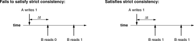
FIGURE 4.8 Strict consistency. Each timeline shows a sequence of read/write events to a particular location. For strict consistency to hold, B must read what A wrote to a given memory location, regardless of how little time passes between the events.
As mentioned, a strictly consistent memory system behaves like a uniprocessor memory system, and note that it would, indeed, solve the problem demonstrated in Figure 4.6. Because C’s read to the data buffer cannot happen before A has finished writing the data buffer, a cache-coherence scheme implementing a strict consistency model will ensure that C cannot get old data.
Sequential Consistency
Despite its appeal of simplicity, the strict consistency model is viewed by many as being far too expensive an implementation: one must give up significant performance to obtain the convenient synchronization benefits. The good news is that, with appropriate use of explicit synchronization techniques, one can write perfectly functional code on multiple processors without having to resort to using strict consistency. A slightly relaxed model that still provides much of the guarantees of the strict model is the sequential consistency model [Lamport 1979], which has the following basic tenet:
The result of an execution is the same as a single interleaving of sequential, program-order accesses from different processors.
What this says is that accesses on different processors must be in program order (no reordering of memory requests is allowed); accesses from different processors can be interleaved freely, but all processors must see the same interleaving. Note that the interleaving may change from run to run of the program. The model is illustrated in Figure 4.9, which compares to Figure 4.8. Here, both sequences are considered valid by the model.
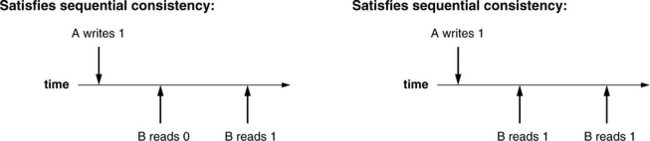
FIGURE 4.9 Sequential consistency. Unlike Figure 4.8, both scenarios are considered valid. Sequential consistency allows an arbitrary delay after which write data becomes available to subsequent reads.
How does the model support the problem in Figure 4.6? At first glance, it would not handle the scenario correctly, which would be a little distressing, but there are more details to consider. In particular, the only realistic way for device A to propagate information to process B is through a device driver, whose invocation would involve a write to the memory system (see Figures 4.10 and 4.11). Figure 4.10 shows the previous example in more detail, including the device driver activity by which A propagates information to B. Figure 4.11 then compares the two scenarios in terms of timelines. Figure 4.11(a) shows the timeline of events as suggested by the original scenario, which would fail to behave as expected in a sequentially consistent memory system: a sequentially consistent model does not require that A’s write to the variable data and B’s write to the variable ready occur in any specific order. In particular, A’s write to data may be seen by the system after B’s write to ready.
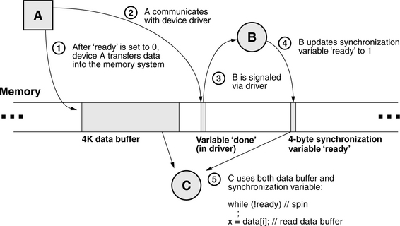
FIGURE 4.10 Race condition example, more detail. The previous model ignored (intentionally) the method by which device A communicates to process B: the device driver. Communication with the device driver is through the memory system—memory locations and/or memory-mapped I/O registers.
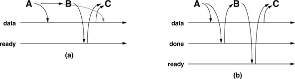
FIGURE 4.11 Realistic picture of data movement and causality. In (a), information propagates directly from A to B without going through the memory system. Because the memory system does not observe the information, it cannot deduce causality, and thus it is possible for A’s write to data to be delayed until after C’s read of data. In reality, A and B are most likely to communicate through a device driver. Assume that the driver has a variable called “done;” (b) shows the picture of data movement and causality that makes sequential consistency work for this scenario.
However, as mentioned, the picture in Figure 4.6 and its corresponding timeline in Figure 4.11(a) are not realistic. The scenario implies that information propagates from A to B without going through the memory system. In contrast, Figure 4.11(b) paints a more realistic picture of what happens, including the movement of data through the device driver, in particular, through a variable in the driver’s space called done. This scenario will behave as expected under a sequentially consistent memory system. In contrast with the simpler picture, in which the transmission of information from A to B is unobserved by the memory system (and thus a coherence mechanism would be hard pressed to deduce causality between the events), in this picture the memory system observes all of the relevant events. In particular, the following event orderings are seen in a sequentially consistent system:
1. A writes data, followed by A writing done (seen by A and thus seen by all)
2. A writes done, followed by B reading done or some other variable written by the device driver (seen by device driver and B and thus seen by all)
3. B reads done … C reads data (seen by B and C and thus by all)
Because sequential consistency requires a global ordering of events that is seen by all clients of the memory system, any ordering seen by any process becomes the ordering that must be guaranteed by the memory system. Thus, C is guaranteed to read the correct version of the data buffer. Note again that the main reason this occurs is because the communication between A and B is actually through the memory system (either a memory location or memory-mapped I/O), and thus, the communication becomes part of the consistency model’s view of causality.
Some example issues to note about the implementation of a sequentially consistent memory system are the following:
• All I/O must go through the coherence scheme. Otherwise, the coherence mechanism would miss A’s write to the location done. Either I/O is memory-mapped, and the I/O locations are within the scope of the coherence mechanism, or, if I/O is not memory-mapped and instead uses special I/O primitives in the instruction set, the coherence scheme must be made aware of these special operations.
• The example assumes that A’s write to the buffer data and A’s write to the variable done are either handled by the same thread of control or at least handled on the same processor core. While this is a reasonable assumption given a uniprocessor implementation, it is not a reasonable assumption for a CMP (chip multiprocessor). If the assumption is not true, then event ordering #1 above (A writes data, followed by A writing done) does not hold true. As far as the system is concerned, if these operations are performed on different processor cores, then they are considered to be “simultaneous” and thus unrelated. In this event, they may be placed in arbitrary order by a sequentially consistent memory system.
• Another implication arises from the definition of sequential consistency: for all clients in the system to agree on an ordering, all clients will have to see external events in a timely manner, a fact that impacts the buffering of operations. In particular, write buffering, something long considered absolutely essential for good performance, is typically disallowed altogether in a sequentially consistent system. Modern processor cores have load/store queues into which write instructions deposit their store data. This store data is not propagated to the memory system (i.e., the local caches, which are visible to the coherence engine) until the write instruction commits, often long after the write is initiated. Thus, a write operation can be buffered for a relatively long period of time relative to local read operations, which are usually sent to the local caches as soon as their target addresses are known.
Sequential consistency requires that local interleavings of events be reflected globally. This is unlikely to happen if the rest of the system finds out about a local write operation much later, at which point all other clients will be forced to back out of operations that conflict with the local ordering of events. Consider the following operations on a given client: a write to location A, followed by reads that cause read misses to locations B, C, and d. If the reads to B, C, and D are seen by the rest of the system before the write to A is propagated out (i.e., the write is buffered until just after the read requests go out), an implementation will be very hard pressed to make all other clients in the system behave as if the write preceded the reads, as it did from the perspective of the initial client. One alternative is to make a node’s write buffer visible to the coherence engine, as suggested in the write-through cache illustration (Figure 4.1). Note that this would require opening up a processor core’s load/store queue to the coherence engine, a cost considered prohibitive if the cores are on separate chips. However, the current industry trend toward multi-cores on-chip may make this scheme viable, at least in providing a locally consistent (chip-wide consistent) cache system.
• A similar implication arises from studying Hennessy and Patterson’s example, originally proposed by Goodman [1989], in which a symmetric race condition occurs between two simultaneously executing processes, P1 and P2:
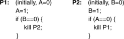
A sequentially consistent memory system will allow 0 or 1 processes to be killed, but not both. For instance, P1 will only try to kill P2 if P1’s read to B occurs before P2’s write to B. By the definition of sequential consistency (which stipulates the in-order execution of memory events), this would imply that P1’s write to A must come before P2’s read of A. The symmetric argument holds equally well.
The implication for an implementation of this model is illustrated in Figure 4.12: not only must writes not be buffered (as mentioned in the previous bullet), but reads must be delayed long enough for write information to propagate to the rest of the system. To ensure that two processes synchronize their memory events in a way that ensures sequential consistency, an implementation must do one of two things: either (i) block all subsequent memory operations following a write until all processor cores have observed the write event or (ii) allow bypassing and/or early execution of memory instructions subsequent to the write operation, but hold their commitment until long enough after the write operation to ensure that all processor cores can observe the write. The implication of speculative bypassing is that if in the meantime a write is observed originating from another core that conflicts with an early executing memory operation, that instruction’s commitment must be halted, its results must be discarded, and the instruction must be reexecuted in light of the new data.
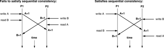
FIGURE 4.12 Sequential consistency and racing threads. A memory system that satisfies sequential consistency must delay all memory operations following a write until the write is observed by all other clients. Otherwise, it would be possible to have both P1 and P2 try to kill each other (as in the scenario on the left), which is disallowed by the sequential model. For example, the earliest that a subsequent read can follow a write is the message-propagation time within the system. Alternatively, a processor can speculate, allowing reads to execute early and patching up if problems are later detected.
As the last two bullets attest, in a sequentially consistent memory system, write performance will be abysmal and read performance will suffer, or the implementation will embody significant complexity to avoid the performance limitations of the model.
Processor Consistency
So how does one avoid the limitations of a sequentially consistent memory system? A further relaxation of memory consistency is called processor consistency [Goodman 1989], also called total store order. Its basic tenet is
Writes from a process are observed by other clients to be in program order; all clients observe a single interleaving of writes from different processors.
This simply removes the read-ordering restriction imposed by sequential consistency: a processor is free to reorder reads ahead of writes without waiting for write data to be propagated to other clients in the system. The racing threads example, if executed on an implementation of processor consistency, can result in both processes killing each other: reads need not block on preceding writes; they may even execute ahead of preceding writes (see Figure 4.13). Similarly, the example illustrated in Figures 4.10 and 4.11 could easily result in unexpected behavior: processor consistency allows reads to go as early as desired, which would allow C’s read of the data buffer to proceed before C’s read of the variable ready finishes (consider, for example, the scenario in which the conditional branch on the value of ready is predicted early and correctly):

FIGURE 4.13 Processor consistency and racing threads. Processor consistency allows each processor or client within the system to reorder freely reads with respect to writes. As a result, the racing threads example can easily result in both processes trying to kill each other (both diagrams illustrate that outcome).
![]()
Ensuring correct behavior in such a consistency model requires the use of explicit release/acquire mechanisms (e.g., see Hennessy and Patterson [1996] for example code) in the update of either the device driver variable done or the variable ready.
Other Consistency Models
This might seem all that is necessary, but there are many further relaxations. For instance,
• Partial store order allows a processor to freely reorder local writes with respect to other local writes.
• Weak consistency allows a processor to freely reorder local writes ahead of local reads.
All of the consistency models up until this point preserve the ordering of synchronization accesses: to wit, locks, barriers, and the like may not be reordered and thus serve as synchronization points. Given this, there are further relaxations of consistency that exploit this.
• Release consistency distinguishes different classes of synchronization accesses (i.e., acquire of a lock versus release of the lock) and enforces synchronization only with respect to the acquire/release operations. When software does an acquire, the memory system updates all protected variables before continuing, and when software does a release, the memory system propagates any changes to the protected variables out to the rest of the system.
Other forms such as entry consistency and lazy release consistency are discussed in Section 4.3.5.
4.3.4 Hardware Cache-Coherence Mechanisms
So, given the various memory-consistency models to choose from, how does one go about supporting one? There are two general implementations:
• Software solutions that build cache coherence into the virtual memory system and add sharing information to the page tables, thereby providing shared memory across a general network
• Hardware solutions that run across dedicated processor busses and come in several flavors, including snoopy schemes and directory-based schemes.
This section will describe hardware solutions. Section 4.3.5 will describe software solutions.
Cache Block States
To begin with, a cache must track the state of its contents, and the states in which a block may find itself can be varied, especially when one considers the information required when multiple clients all want access to the same data. Some of the requirements facing a cache include the following:
• The cache must be able to enforce exclusive updating of lines, to preserve the illusion that a single writer exists in the system at any given moment. This is perhaps the easiest way to enforce a global sequence of write events to a particular address. Caches typically track this with Modified and/or Exclusive states (M/E states).
• The cache must be able to tell if a cache block is out of sync with the rest of the system due to a local write event. Caches typically track this with Modified and/or Owned states (M/O states).
• An implementation can be more efficient if it knows when a client only needs a readable copy of a particular datum and does not intend to write to it. Caches typically track this with a Shared state (S).
(I)nvalid: Invalid means that the cache block is in an uninitialized state.
(M)odified: read-writable, forwardable, dirty: Modified means that the state of the cache block has been changed by the processor; the block is dirty. This usually happens when a processor overwrites (part of) the block via a store instruction. The client with a block in this state has the only cached copy of that block in the system and responds to snoops for this block by forwarding the block (returning the data in a response message) and also writing the block back to the backing store.
(S)hared: read-only (can be clean or dirty): Shared means that the cache line in question may have multiple copies in the caches of multiple clients. Being in a Shared state does not imply that the cache block is actively being shared among processes. Rather, it implies that another copy of the data is held in a remote processor’s cache.
(E)xclusive: read-writable, clean: Exclusive means that a processor can modify a given cache block without informing any other clients. To write a cache block, the processor must first acquire the block in an exclusive state. Thus, even if the processor holds a copy of the data in the data cache, it first requires a transaction to the backing store (or wherever the coherence mechanism is homed) to request the data in Exclusive state. The client with a block in this state has the only cached copy of that block in the system, and it may forward that block in response to a snoop request. Once written by the client, the block is transitioned to the Modified state.
(O)wned: read-only, forwardable, dirty: Owned means that a cache can send other clients a copy of the (dirty) data without needing to write back, but the Owner is the only one who can write the block back to the backing store. The block is read-only: the client holding the block may forward it, but may not write it.
Note that this is just a sample of common states. Protocols exist that make use of many other states as well. This is enough to get an idea of what has been done.
Using Write-Through Caches (SI)
We start with a simple example: a system of write-through caches, as shown in Figure 4.14. In such a scheme, all writes are transmitted directly through to memory, even if considering the existence of write buffers or write caches. Because the backing store is known to be consistent with each cache at all times, a cache may “silently” evict any cache block at any time, even if that block was recently written by the processor.
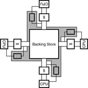
In such a scheme, cache blocks need only track SI states: a block is either present in a cache or not. Writes are propagated to the backing store immediately by definition of the scheme, and thus, in a sense, the problem of handling multiple writers to the same datum is transferred to the shoulders of the backing store.
Write-update: Typically, write events will cause one of two responses: write-update or write-invalidate. A write-update policy will transparently update the various cached copies of a block: if processor A writes to a block, the write data will find its way into all cached copies of that block. This clearly requires significant bandwidth: every local write immediately becomes a global broadcast of data. The mechanism, though expensive, is extremely beneficial in handling applications that make use of widely shared data. It is non-trivial to implement because it requires shoving unsolicited data into another client’s data cache.
Write-invalidate: The alternative to write-update is a write-invalidate policy, in which all cached copies of the written block are set to the Invalid state. All clients actively sharing the block will suddenly find their cached copies unavailable, and each must re-request the block to continue using it. This can be less bandwidth-intensive than a write-update scheme, but the general implementation mechanism is similar: an address must be sent to remote caches, each of which must check in its tag store to see if the affected datum is present.
The primary difference between the two is that in a write-invalidate policy, there can be only one writable copy of a datum in the system at any given point in time. In contrast, a write-update policy can easily support multiple writers, and, in fact, this is precisely what software implementations of cache coherence do. In addition, note that, by its nature, a write-update scheme makes sequential consistency extremely hard to implement: to guarantee that all clients see all operations in the same order, an implementation must guarantee that all update messages are interleaved with all other system-wide coherence messages in the same order for all nodes. While systems exist that do this (e.g., ISIS [Birman & Joseph 1987]), they tend to be relatively slow.
Using Write-Back Caches (MSI)
To reduce bandwidth requirements, one can change the scheme slightly (use write-back caches instead of write-through caches) and not propagate write data immediately. The scheme exploits write-coalescing in the data caches: multiple writes to the same cache block will not necessarily generate multiple coherence broadcasts to the system; rather, coherence messages will only be sent out when the written block is removed from the cache. Unlike the write-through scenario, in this scheme, data in a particular cache may be out of sync with the backing store and the other clients in the system. The implementation must ensure that this allows no situations that would be deemed incorrect by the chosen consistency model. Figure 4.15 illustrates a possible state machine for the implementation.
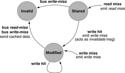
FIGURE 4.15 State machine for an MSI protocol [based on Archibald and Baer 1986]. Boldface font indicates observed action (e.g., local write miss to block in question, or a bus transaction from another cache on a block address matching in the local tags). Regular font indicates response action taken by local cache.
Whereas a write-through cache is permitted to evict a block silently at any time (e.g., to make room for incoming data), a write-back cache must first update the backing store before evicting a block, if the evicted block contains newer data than the backing store. To handle this, the cache must add a new state, Modified, to keep track of which blocks are dirty and must be written back to the backing store. As with the write-through example, writes may be handled with either a write-update or write-invalidate policy.
MSI-protocol implementations typically require that reads to Invalid blocks (i.e., read misses) first ensure that no other client holds a Modified copy of the requested block and that a cache with a Modified block returns the written data to a requestor immediately. A write request to a Shared or Invalid block must first notify all other client caches so that they can change their local copies of the block to the Invalid state. These steps ensure that the most recently written data in the system is relayed to any client that wants to read the block. While this mirrors the read-modify-write nature of many data accesses, it forces the process to require two steps in all instances.
In particular, when an MSI client acquires a block on a read miss, the block is acquired in the Shared state, and to write it the client must then follow this with a write-invalidate broadcast so that it can place the block in the Modified state and overwrite the block with new data. In an alternative MSI implementation, all reads could use a write-invalidate broadcast to acquire all read blocks in a Modified state, just in case they might wish to write them later. This latter approach, while reducing the broadcast messages required for a write operation, would eliminate the possibility of real read-sharing (every block would be cached in, at most, one place). In addition, even if the block is not, in fact, modified by the requesting client, the fact that it is acquired in the Modified state implies that it must be written back to the backing store upon eviction, thereby turning all memory operations into de facto writes.
Alternatively, the addition of the Exclusive state solves the same problem: a MESI protocol provides another mechanism for acquiring read data that requires no global update or broadcast request when the client chooses to write the acquired block.
Reducing Write Broadcasts (MESI)
To provide a lower overhead write mechanism, the Exclusive state is added to the system’s writeback caches. A client in the system may not write to a cache block unless it first acquires a copy of the block in the Exclusive state, and only one system-wide copy of that block may be marked Exclusive. Even if a client has a readable copy of the block in its data cache (e.g., in the Shared state), the client may not write the block unless it first acquires the block in an Exclusive state. Figure 4.16 illustrates a possible state machine for the implementation.
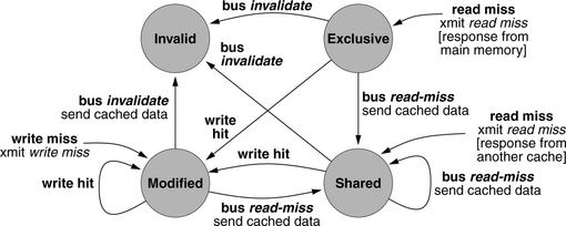
FIGURE 4.16 State machine for a MESI protocol [based on Archibald and Baer 1986]. Boldface font indicates observed action (e.g., local write miss to block in question, or a bus transaction from another cache on a block address matching in the local tags). Regular font indicates response action taken by local cache.
Compared to the Modified and Shared states, the Exclusive state is somewhere in between—a state in which the client has the authority to write the block, but the block is not yet out of sync with the backing store. A block in this state can be written by the client without first issuing a write-invalidate, or it can be forwarded to another client without the need to update the backing store (in which case it can no longer be marked Exclusive). In a MESI implementation, the first step in a write operation is for a processor to perform a read-exclusive bus transaction. This informs all clients in the system of an upcoming write to the requested block, and it typically invalidates all extant copies of the block found in client caches. Once the block is acquired in an Exclusive state, the processor may freely overwrite the data at will. When the cache block is written, it changes to the Modified state, which indicates that the data is dirty—out of sync with the backing store and requiring a writeback at a later time.
The written data becomes visible to the rest of the system later when the block is evicted from the writer’s cache, causing a write-back to the backing store. Alternatively, the cache-coherence mechanism could prompt the Exclusive owner to propagate changes back to the backing store early if, in the meantime, another client in the system experiences a read miss on the block, its cached copy having been invalidated (e.g., see Section 4.1.3). As with the MSI protocol, the chosen memory-consistency model defines whether a delayed write-back is considered correct behavior; most implementations require that a cache with a Modified block return the data immediately, but one can envision implementations of relaxed consistency models that allow the holder of the Modified block to delay writing the data back to the backing store until it is convenient for the owner of the block. Regardless of the implementation, the block is returned to the Exclusive state once the backing store is consistent with the cached copy.
One downside of the MESI protocol (as with MSI and SI protocols as well) is that, in a sense, all coherence activity passes through a centralized point (the backing store). While this may make sense for a typical symmetric multiprocessor organization with multiple clients and a central backing store, it may make less sense in a system where control is distributed across the clients rather than centralized in a single place. Alternatively, the protocol could be enhanced to support client-to-client transactions that need not pass through the backing store. This is one function of the Owned state that is added to MOESI protocols.
Distributing Control (MOESI)
To make it easier to distribute the task of maintaining cache coherence, the Owned state is added to the system. This state indicates transfer of ownership of a block from a writer to another client directly. Thus, the MOESI protocol is useful particularly in systems that have good client-to-client bandwidth, but not necessarily good bandwidth between the client and the backing store (e.g., CMPs or NUCA organizations).
In a MOESI system, just like a MESI system, a single client may hold a block in Exclusive state, enabling the client to write the block. When the block is written, the block becomes Modified. Unlike a MESI protocol, the MOESI protocol allows the holder of a Modified block to transfer the block directly to another client and to bypass the backing store completely, at which point the new client places the block into the Owned state. Unlike the Exclusive state, the Owned state allows the block to be replicated to other clients (where it would be held in a Shared state). Only the holder of the Owned block may write the block back to the backing store, and an Owned block as well as any Shared copies derived from it may be out of sync (dirty) with respect to the backing store.
The primary mechanism that exploits the Owned state is “snarfing,” illustrated in Figure 4.17. MOESI-based snarfing cache systems are found in AMD’s Opteron and Athlon MP [Keltcher 2002, Huynh 2003] and Sun’s UltraSPARC-I [Sun 1995]. In the process of snarfing, one processor’s cache grabs an item off the bus that another processor’s cache is writing back to main memory, with the expectation that the other processor may need that item in the near future. When a cache snarfs data off the shared bus, it tags the cache block locally as Owned. The idea behind this activity is that it would be far faster to retrieve the “snarfed” object from another cache than to retrieve it from main memory, and doing so would significantly reduce traffic to the DRAM system. This is the distributed processor cache realization of an observation made in the realm of distributed file caches [Nelson et al. 1988], namely that it can be faster to load a page of data over a 10-Mbps Ethernet link from the physical memory of a file server than it is to load the page from local disk. To wit, it can be faster to load a cache block from a neighboring microprocessor’s cache than it is to load the cache block from main memory.
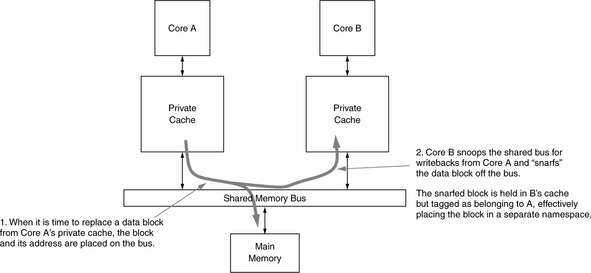
Cache Organization Issues
Several issues related to cache organization arise. The choice to maintain inclusion impacts the implementation significantly, and the choice of a private versus shared last-level cache can dramatically change application performance [Jaleel & Jacob 2006] as well as the coherence implementation.
Inclusive, Exclusive, or Non-Inclusive?
First, the following are issues to consider in the choice of inclusive versus exclusive or non-inclusive caches:
• Inclusive caches simplify the coherence mechanism in many ways. For instance, the coherence scheme need probe only the lowest level of a client’s cache when performing invalidates or updates. If a block is not found in the lowest level of an inclusive cache hierarchy, the block cannot be found at a higher level. This allows a coherence probe to proceed without disturbing the core’s interaction with the L1 cache. However, the duplication of data (and wastage of die area) in an inclusive cache hierarchy can become significant, especially if multiple processor cores and their associated L1/L2 caches feed off the same lower level shared cache.
• The advantage of exclusive caches is that they avoid the duplication of data and wastage of die area associated with inclusive caches. However, the costs are significant: a coherence probe must search the entire hierarchy, not just the lowest level cache (note that rather than probing all levels of the cache, potentially interrupting/stalling the core to probe the L1 cache, the higher level tag sets are typically replicated down at the last-level cache to centralize the tags needed for a coherence check). In addition, managing the cascading evictions and allocations from/into the L1 cache is nontrivial.
• Non-inclusive caches attempt to achieve the best of both worlds. A non-inclusive cache tries neither to ensure exclusion nor to maintain inclusion. For instance, an inclusive cache will evict multiple blocks from an L1 cache in response to a single-block eviction from the L2 cache when the L1/L2 block sizes differ. In contrast, a non-inclusive cache makes no attempt to do so, and thus, the L1 cache may retain portions of a block recently evicted from the L2 cache. An exclusive cache will ensure that no data from a block promoted from the L2 cache to the L1 cache remains in the L2 cache, which will require data to be thrown away, either from the promoted block or from extra evicted L1 blocks. In contrast, a non-inclusive cache makes no attempt to ensure this. The disadvantage of the scheme is that, like the exclusive cache hierarchy, it must maintain copies of the higher level tag sets down with the last-level cache to avoid interrupting the processor cores in response to coherence traffic.
Shared or Private Last-Level Cache?
Another cache-organization issue is the design choice of a shared versus private last-level cache [Jaleel & Jacob, 2006]. As multi-core processors become pervasive and the number of cores increases, a key design issue facing processor architects will be the hierarchy and policies for the last-level cache (LLC). The most important application characteristics that drive this cache hierarchy and design are the amount and type of sharing exhibited by important multi-threaded applications. For example, if the target multi-threaded applications exhibit little or no sharing, and the threads have similar working-set sizes, a simple “SMP on a chip” strategy may be the best approach. In such a case, each core has its own private cache hierarchy. Any memory block that is shared by more than one core is replicated in the hierarchies of the respective cores, thereby lowering the effective cache capacity. On a cache miss, the hierarchies of all the other cores’ caches must be snooped (depending on the specifics of the inclusion policy).
On the other hand, if the target multi-threaded applications exhibit a significant amount of sharing, or if the threads have varying working-set sizes, a shared-cache CMP is more attractive. In this case, a single, large, last-level cache, which may be centralized or distributed, depending on bandwidth requirements, is shared by all the on-die cores. Cache blocks that are referenced by more than one core are not replicated in the shared cache. Furthermore, the shared cache naturally accommodates variations between the working-set sizes of the different threads. In essence (and at the risk of oversimplifying), the CMP design team, building a chip with C cores and room for N bytes of last-level cache, must decide between building C private caches of N/C bytes each or one large shared cache of N bytes. Of course, there is a large solution space between the two extremes, including replication of read-only blocks, migration of blocks, and selective exclusion, to name just a few. However, the key application characteristics concerning the amount of data sharing and type of sharing are important for the entire design space.
Note that the choice of LLC cache organization impacts how and where the cache coherence can be implemented, at least to maintain coherence between the caches on-chip. In a private cache organization, coherence must be maintained after the last-level cache. In a shared-cache organization, coherence can be part of the cache’s existing interconnect infrastructure.
Interconnect Options and Their Ramifications
Figure 4.18 illustrates some of the choices facing a designer when organizing the backing store. The backing store is an abstraction, meaning everything beyond this point, but the realization of the abstraction in a physical system will significantly impact the design of the associated coherence scheme.

FIGURE 4.18 The many faces of backing store. The backing store in a multiprocessor system can take on many forms. In particular, a primary characteristic is whether the backing store is distributed or not. Moreover, the choices within a distributed organization are just as varied. The two organizations on the bottom right are different implementations of the design on the bottom left.
We will return to this later at the end of the section, but for now it is worthwhile to consider the ramifications of system organization on the design of a coherence protocol. Shared-bus organizations lend themselves to protocols that rely upon each cache observing all system-wide activity and responding to any requests that apply. Distributed organizations (called links-based systems, as opposed to bus-based systems) imply a less centralized approach, because, unless memory requests and/or coherence messages are explicitly relayed to achieve an effective broadcast within the system, not all clients will be aware of all system-wide activity. The distributed organization also suggests, at least potentially, a less serialized approach. It exhibits the obvious advantage that because different subnets can be operative simultaneously handling different requests, much more communication can be sustained throughout the system. The decentralization, while creating a potential controls problem, increases potential bandwidth and thus performance tremendously. Links-based organizations typically exhibit anywhere from a factor of two to an order of magnitude higher sustainable bandwidth than the fastest shared-bus organizations.
The two physical organizations translate to two different styles of coherence mechanism, though it is possible to implement either type of mechanism on either of the physical organizations. The two main types of cache-coherence implementations are directory based and snoop based (i.e., “snoopy”). A directory-based implementation maintains the state of each cache block in a data structure associated with that cache block. The data structure contains such information as the block’s ownership, its sharing status, etc. These data structures are all held together in a directory, which can be centralized or distributed; when a client makes a request for a cache block, its corresponding directory entry is first consulted to determine the appropriate course of action.
A snoop-based scheme uses no such per-block data structure. Instead, the appropriate course of action is determined by consulting every client in the system. On every request, each cache in the system is consulted and responds with information on the requested block; the collected information indicates the appropriate response. For instance, rather than looking up the owner of a block in the block’s directory entry as would be the appropriate step in a directory-based scheme, in a snoopy scheme the owner of the block actively responds to a coherence broadcast, indicating ownership and returning the requested data (if such is the appropriate response).
Snoopy Protocols
In a snoopy protocol, all coherence-related activity is broadcast to all processors. All processors analyze all activity, and each reacts to the information passing through the system based on the contents of its caches. For example, if one processor is writing to a given data cache line, and another processor has a copy of the data cache line, then the second processor must invalidate its own cache line. After writing the block, the first processor now has a dirty copy. If the second processor then makes a read request to that block, the first processor must provide it.
Snoopy protocols seem to imply the existence of a common bus for their implementation, but they need not use common busses if there is agreement between clients to propagate messages (e.g., thereby emulating bus-based broadcasts). The fundamental tenet of a snoopy protocol is that every cache watches the system, observes every request, checks its local state to determine if it should become involved, and does so if appropriate. Global state is maintained by a distributed state machine in the collected tags of the distributed cache; the caches all participate together in the state transitions. In a bus-based system, this means that every cache sits on the shared bus and watches every request go by (“snoops the bus”). To determine the correct location or state of a block in a links-based system, explicit messages must be sent to snoop the caches of other nodes.
Because the coherence communication is fundamentally between caches, which together manage the state of the system’s cached blocks, memory bandwidth to the backing store is less of a concern. The primary issue is to supply enough inter-cache bandwidth to support the expected coherence traffic, which tends to grow linearly (as O(n)) with the number of clients in the system. Another issue is cache bandwidth. Because the caches manage the coherence state of the system’s blocks, and because potentially every memory request may result in multiple coherence probes above and beyond the cache probes required by a processor core to execute its software, caches must be designed to handle multiple simultaneous probes. As described earlier, inclusive caches make this relatively simple, as the lowest level cache can handle coherence probes at the same time that the highest level caches are handling processor-core data requests. Other cache organizations require multiple tag sets to handle the requisite probe bandwidth.
Source snoopy: One of the implementation choices in a snoopy protocol is a source-snoopy (2-hop) implementation versus a home-snoopy (3-hop) implementation. In a source-snoopy protocol, snoops are sent from a requestor to all peer clients. This tends to result in a relatively low average response time to requests, but an implementation must deal with issues such as many-to-many race conditions. Figure 4.19 illustrates the messages that are sent in a simple read-miss event in a source-snoopy protocol. Figure 4.20 illustrates the messages that are sent in a slightly more complex scenario (read miss to a Modified block). Since all coherence messages are broadcasts, the owner of a block will always be a recipient. When a client cache broadcasts a read request on a cache miss, the current owner of the block writes the data back to the backing store (e.g., assuming a MESI protocol) and sends a copy of the data to the requesting client. The requestor receives the data in two network hops.
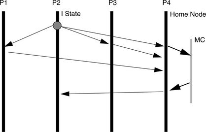

Home snoopy: In a home-snoopy protocol, requests are sent to a datum’s home node first, and then the home node sends snoops to other clients. The mechanism is much simpler than source-snoopy protocols because the serialization eliminates race conditions. However, the obvious cost is in a higher average latency. For example, Figure 4.21 illustrates the slightly more complex read-miss scenario in the context of a home-snoopy protocol. When a client experiences a read miss in its local cache, the initial coherence message is not a broadcast to the entire system, but a request directed at the block’s home node, which then generates the appropriate snoop requests. Ultimately, the requested data is sent to the original client after three network hops.
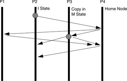
Directory-Based Protocols
An alternative to snoopy implementations is to centralize the state information in a directory, as opposed to distributing the state information in the tags of the distributed cache. Thus, a directory-based protocol does not need the cooperation of all the caches in the system; a data request need only consult the directory to determine the correct course of action. The directory may be centralized or distributed, but the fact that it gathers all state information into one place simplifies the system-level state machine that implements the coherence scheme. A directory entry typically includes the following information:
• Current state of the block (cached or non-cached, readable and/or writable)
• What clients in the system have a copy of the block
• An identification of the client responsible for write-back, if such an owner exists (i.e., if the block is cached in a writable state)
On a local cache miss, a client first consults the directory entry for the requested block; the directory entry indicates where the block can be found and in what state, and the client makes a request directly to the client/s holding copies of the block. The mechanism has constant overhead in message passing (scales as O(1) with the number of clients in the system), but it tends to require more bandwidth to the backing store than a snoopy protocol, because the directory structure, being large, is typically held in the backing store. In addition, the directory now becomes a point of serialization in the protocol and thus potentially limits performance (just as the shared bus in a bus-based snoopy protocol is a point of serialization and thus potentially limits performance). Directories are common for links-based organizations because, as a linked system scales in size, the latency to snoop the clusters of processors can quickly become greater than the latency to a node’s local backing store (its DRAM system).
Full directory: There are several different options for implementation. First is the size and scope of the directory. As mentioned, the directory structure can be quite large, as a directory entry is on the same size scale of the cache block it manages. A full directory implementation maintains one directory entry for every cached block in the system, i.e., every block that is found within the distributed cache, not every cache-block-sized chunk of the backing store (though there have been proposals for such an implementation). A miss to the directory—a probe of the directory that fails to match the requested block ID—thus indicates that the requested block is not cached within the system; the requested block will necessarily come from the backing store. A full directory is relatively large and held in the backing store; e.g., in a multiprocessor system, it is typically held in the DRAM system.
Partial and hybrid directories: A partial directory implementation reduces the size of the directory considerably by maintaining entries for only a subset of the cached blocks. A miss to the directory thus conveys no information as it does with a full directory implementation, and the partial directory system must then resort to a snoopy protocol to find the state of the requested block. In such a case, all caches in the system are probed. Because the partial directory is significantly smaller than a full directory, it is typically held in SRAM, thereby improving both the directory’s access time and, at least potentially, any serialization issues in those cases when a directory probe hits. Similar to the partial directory is the hybrid directory: a multilevel, directory cache arrangement, where a smaller version of the directory, a cache of the full directory, is probed first. The directory cache can be small enough to be stored in SRAm. It is similar to the partial directory, except that, in the case of an initial directoryprobe miss, the full directory is probed instead of executing a system-wide snoop.
Explicit and coarse pointers: Another implementation option is the granularity with which the directory maintains information on clients holding cached copies of a shared block. Within each directory entry is a list of clients sharing that block, typically represented by a bit vector of Boolean values (e.g., “1” indicates the client has a copy of the block, and “0” indicates the client does not have a copy of the block). An implementation using explicit pointers maintains a bit in the vector for each client in the system. An implementation using coarse pointers overloads the bits to represent multiple clients. For example, each bit in the vector could represent a different, tightly coupled cluster of clients within the system. Setting the bit would indicate that one or more client caches within that cluster hold a copy of the block, but there would be no way to determine which cache/s within the cluster has the block.
Perspective on the Coherence Point
Figure 4.22 illustrates three different topologies for small-scale computer systems that are typically found with one to four processors: the classic small-system system topology, the point-to-point processor-controller system topology, and the integrated-controller system topology.
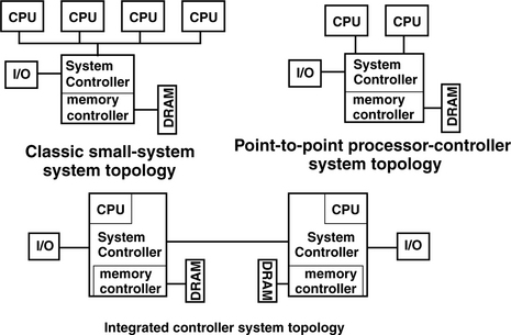
The classic small-system topology illustrates the topology of many different systems. For example, platforms based on Intel’s Pentium, Pentium II, Pentium III, Pentium 4, and Itanium processors utilize the classic small-system topology. Also, platforms based on PowerPC 7xx and 74xx series of processors, as well as PA-RISC PA-7200 and PA-8000 processors that utilize the HP Runway bus, similarly utilize the classic small-system topology. In the classic small-system topology, one to four processors are connected to the system controller through a shared processor bus. The processors and the system controller dynamically negotiate for access to the shared processor bus. The owner of the processor bus then uses the shared processor bus to transmit transaction requests, memory addresses, snoop coherency results, transmission error signals, and data.
The point-to-point processor-controller system topology illustrates the topology of systems based on processors such as the Alpha 21264 (EV6), AMD K7, and IBM’s PowerPC 970 processors. In the point-to-point processor-controller system topology, one to two processors are connected directly to dedicated ports on the system controller. The point-to-point system topology does not limit the number of processors connected to the system controller, but since the processor connects directly to the system controller, the system controller must have enough pins on the package of the controller and die area devoted to the interface of each processor in the system controller. As a result, systems such as Alpha 21264 processor-based multiprocessor systems that utilize more than two processors with point-to-point processor-controller system topology rely on multiple support chips rather than a single system controller. The point-to-point processor-controller system topology represents a gradual evolution from the classic small-system topology. The point-to-point processor-controller system topology provides an independent datapath between each processor and the system controller, and higher bandwidth is potentially available to the processor in the point-to-point processor-controller system topology as compared to the classic small-system topology.
The integrated system-controller system topology represents the topology of systems such as those based on the AMD Opteron or Alpha 21364 (EV7) processors. In these processors, the system controller and the DRAM memory controller are directly integrated into the processor. The integration of the DRAM memory controller greatly reduces the memory-access latency in a uniprocessor configuration. However, since each processor in a system has its own memory controller, the memory in the system is distributed throughout the system. In these systems, memory-access latency depends on the type of cache coherency protocol utilized, the number of processors in the system, and the location of the memory to be accessed.
In most modern computer systems, both uniprocessor and multiprocessor, the burden of cache coherence is placed in hardware, and cache coherence is enforced at the granularity of transactions. In these systems, the system controller is typically the coherence point. That is, when a memory reference misses in the processor’s private caches, that processor issues a transaction request to the system controller for the desired cache block. In response to the transaction request, the system controller is expected to return the most up-to-date copy data for the requested cache block. As described earlier, the requirement that the data must be the most up-to-date copy means that the system controller is responsible for checking the private caches of other processors in the system for copies of the requested cache line and invalidating the data in those cache lines if necessary. Figure 4.23 abstractly illustrates the concept of the coherence point. In Figure 4.23, the processor issues a transaction request, and coherence checks are issued to other processors in the system concurrently with the read command to the DRAM devices. The coherence status of the transaction and the data for the read transaction are collected at the coherence point, and the coherence point ensures that the data returned to the processor is the most up-to-date copy of the cache line in the system. Figure 4.24 illustrates the timing implication. Data is not returned to a requesting client until coherence is assured, and this remains true whether the coherence check takes longer than a DRAM access or not.
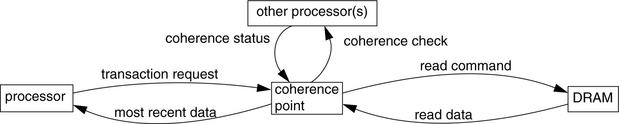
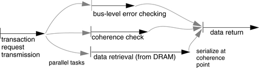
Figure 4.25 shows the respective coherence points in each system topology. These are points of synchronization at which the coherence information for each memory request is checked and processed. In the case of the classic system topology, the processors must dynamically arbitrate for the bus, which provides a form of serialization, and the client-level snooping of all bus transactions is what drives the distributed state machine implementing the consistency model. Thus, the coherence point is at the bus; coherence is assured before a request reaches the system controller. The coherence point is pushed a bit farther out for the point-to-point system topology, to the system controller, which is the first physical entity that sees all transactions (i.e., one microprocessor cannot see the bus transactions of another). Thus, the system controller is the coherence point. In the integrated-controller topology, coherence is assured by a distributed state machine that lies beyond the system controller. Thus, the coherence point moves a bit farther out toward the rest of the system. Compare this with Figure 4.24; the implication is that, in an integrated-controller system in which each node has its own partition of the backing store, the cost of performing coherence can easily outweigh the cost of going to the local backing store. This implication can easily drive implementations. For instance, a designer might want to proceed with a memory request speculatively before the coherence state of a block is known. This would require a client to back out of a set of operations if it is later determined that the data used (e.g., returned from the local DRAM system) was out of sync with another cached copy elsewhere in the system. However, such speculation would tend to reduce memory-request latency. Other implementations could include locally held partitions of the global directory that cover only blocks from the local memory system.
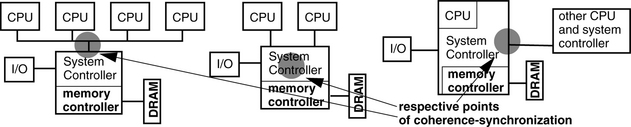
4.3.5 Software Cache-Coherence Mechanisms
At first glance, software-based cache-coherence implementations would simply mirror hardware-based implementations. However, as pioneers in the field point out [Li & Hudak 1986, 1989], there is at least one fundamental difference between the two: namely that the communication latency between clients in a software-based implementation is non-trivial compared to the cost of accessing a shared datum, and, consequently, the cost of coherence maintenance is extremely high relative to hardware-based implementations. In comparison, the cost of resolving coherence issues in a shared-bus implementation occurs at the bus level while making a request for a datum in physical memory. Coherence resolution is simply part of the cost of access. In a software implementation, communication may be between operating system kernels on different nodes or even between application-level processes on different nodes; the latency of communication may be many times that of accessing the backing store.
To illustrate some of the approaches used, we briefly discuss four of the earliest shared virtual memory systems:
• Ivy [Li & Hudak 1986, 1989], known for distinguishing the granularity of data transfer (large) from the granularity of coherence maintenance (small)
• Munin [Bennett et al. 1990a, b, c, Carter et al. 1991], known for its use of twinning and diffing to perform write merging, as well as its use of release consistency [Gharachorloo et al. 1990]
• Midway [Bershad & Zekauskas 1991, Bershad et al. 1993, Zekauskas et al. 1994], known for its introduction of entry consistency
• TreadMarks [Keleher et al. 1992, 1994], known for its introduction of lazy release consistency
These are admittedly focused on a narrow range of software implementations, namely those integrated with the virtual memory system. Many other software-based cache schemes exist, including those that distribute computational objects or web documents over a network (e.g., Emerald [Jul et al. 1988], Orca [Bal et al. 1992], and numerous web-proxy mechanisms), those that provide uniprocessor cache coherence in software (e.g., Wheeler and Bershad [1992]), and even those that provide multiprocessor cache coherence in software (recall from the mid-1990s the PowerPC-603-based BeBoxen, which implemented cache coherence between two microprocessors without the benefit of cache-coherence hardware [Gassée 1996]).
Ivy
As mentioned earlier, a disparity exists between the cost of access in a software-based cache-coherence implementation and the cost of access in a hardware-based implementation. In a hardware scheme, the coherence management is simply wrapped into the cost of accessing the backing store, while in a software scheme, the management costs are additive and can be extremely high. One of the fundamental results to come out of the shared virtual memory research, addressed in the Ivy system [Li & Hudak 1986, 1989], is a mechanism that addresses this disparity, namely the separation of data-access granularity from coherence-maintenance granularity.
In a shared virtual memory system, the granularity of data access is typically a page, as defined by the virtual memory system: when a node requests a readable copy of the backing store, an entire page of data is transferred to the requesting node. This amortizes the high cost of a network access over a relatively large amount of data transferred. However, the large granularity of data access gives rise to false sharing, a scenario in which two different clients try to write to different locations within the same page. Such a scenario is not true sharing; however, because the granularity of access is large, it appears to the coherence engine to be an instance of sharing, and the performance hit of ping-ponging the page back and forth between the two clients is predictably unacceptable.
Ivy’s solution to the problem is to monitor coherence on a different scale. When the page is written, the coherence mechanism does not try to reconcile the entire page with clients that might be sharing the data. Rather, the coherence mechanism tracks write activity at the granularity of cache blocks, a choice that reduces the coherence-related communication tremendously.
Munin
Munin takes the concept of multiple writers a bit further [Bennett et al. 1990, Carter et al. 1991]. In the Munin system, write synchronization happens only at explicit boundaries, particularly at the release of a synchronization variable. The model is called release consistency [Gharachorloo et al. 1990]; earlier distributed shared memory systems implement sequential consistency. In Munin, clients can freely update shared variables between the acquisition and release of a synchronization variable without generating coherence traffic until the release point, at which point the shared variables are reconciled with the rest of the system.
The coherence engine supports multiple writers to the same data object, but the burden of correct behavior is placed on the shoulders of the programmer, for instance, to ensure that multiple concurrent writers to the same data array write to different parts of the array. In the case of multiple writers, a copy of the page, called a twin, is made, which is later used to determine which words within the page were modified. At the release point, the coherence engine merges write data from multiple clients transparently to application processes. Any object that has a twin is first diffed against its twin; the diffs represent the changes made by the client and are guaranteed by the programmer not to conflict/overlap with changes made by other clients to the same object. The coherence engine propagates the diffs out to all clients requiring updates, and the clients update their local copies with the changes. The use of release consistency allows many changes to be encapsulated via a diff into a single update message.
Midway
Midway introduces entry consistency, a consistency model that further reduces the cost of coherence management [Bershad & Zekauskas 1991, Bershad et al. 1993, Zekauskas et al. 1994]. Whereas release consistency in Munin proactively propagates changes to shared data to all sharing clients at the time of a release operation, Midway only propagates the changes to clients that explicitly request those changes by later performing an acquire operation on one of the changed variables. Thus, at an acquire operation, a client requests the latest copies of those variables protected within the critical section of code defined by the acquire/release pair. The release operation does not cause the coherence engine to propagate changes to the rest of the system. Rather, the release signals to the coherence engine that access to the encapsulated variable/s is now allowed.
For this to work, shared variables must be identified and associated with a particular synchronization variable, and clients must access shared variables only inside critical regions (acquire/release pairs on the appropriate synchronization variable). The result is that inter-process communication, rather than being a constant in the number of release operations, instead depends entirely on the degree of real sharing within the application.
TreadMarks
TreadMarks [Keleher et al. 1994], another widely cited implementation of distributed shared memory, is known for its introduction of lazy release consistency [Keleher et al. 1992], a consistency model that shares many features of entry consistency [Bershad & Zekauskas 1991]. Most importantly, both models propagate write information from producer to consumer only at the time of the consuming client’s acquire operation, a detail that improves network communication tremendously over other mechanisms. The primary difference between the two is in the low-level implementation details of the two systems that implement these models (Midway and TreadMarks) and not necessarily in the consistency models themselves. In particular, Midway requires shared variables to be associated with specific synchronization variables; when an acquire operation is performed on a particular synchronization variable, diffs for only those variables associated with the synchronization variable are propagated to the acquiring client. TreadMarks requires shared variables to be protected within critical sections, but shared variables need not be associated with a particular synchronization variable. On an acquire operation, prior release operations become visible. In addition, Midway uses an update protocol, and TreadMarks uses an invalidate protocol. The two perform very similarly [Adve et al. 1996].
1Much has been written on the development of write buffers and write caches (a good starting point is work by Jouppi [1993]). We will only discuss the minimum details of their operation.
2Unique within the system is not hard to guarantee: if the software has a unique ID, it need only generate a number that is unique locally, for example, a sequence number (incremented for every packet sent out) concatenated with a timestamp, all concatenated with the software Id.
3For example, both causal consistency and pipelined RAM consistency allow multiple writes to a single memory address to take effect in different order to different clients [Tanenbaum 1995]. Thus, whereas client A would see the value “1” written to a memory location followed by the value “2,” client B could see the value 2 written, followed by the value 1.
4A possible explanation of/justification for the existence of both terms is that coherence arose in the context of uniprocessor systems, and the term consistency was used to describe the behavior of multiprocessor systems rather than redefining or supplanting the original term.
5For a thorough discussion of synchronization primitives such as fences and barriers and release and acquire operations, see, for example, Hennessy and Patterson [1996].
6It is important to remember that, in discussions of memory-consistency models, the notion of when a write happens means when its results are observed and not when the write is issued.
7For instance, numerous schemes exist that maintain time in a distributed system, including virtual clocks, causal clocks, broadcasts and revocations, timestamps, etc. So there are numerous ways to support such a scheme.