
The Cache Layer
The disk drive’s cache is a great equalizer of performance. It can reduce the net performance gap between two drives with a vast difference in raw performance capability such as seek time and rotational speed. Cases exist in which a mechanically slow desktop or even mobile drive whose caching strategy is better tuned for certain applications outperforms a much faster server drive whose cache is not designed to handle those applications. Caching is, therefore, a key factor in a disk drive’s performance, whose importance is equal to other basic drive attributes such as seek time, rotational speed, and data rate.
Because of its importance, this chapter is devoted to disk cache exclusively. There are two aspects to the design of a disk cache. One aspect is its logical organization, which deals with how the memory space for caching is structured and allocated and how data is placed and identified within the cache memory. A second aspect is the cache’s content- and consistency-management algorithms, which define the behavior of the cache and include deciding which piece of old data to throw out (deallocate) to make room for new data, what and how much data to prefetch, etc. Hence, the organizational aspect of cache design deals with where to put data, and the algorithmic aspect deals with what data to put in the cache. These two aspects are orthogonal, in the sense that one does not depend on the other, although certain algorithms may be easier to implement with a particular type of organization. Both aspects will be discussed in this chapter, following an overview of caching at the disk drive level.
22.1 Disk Cache
Today’s disk drives all come with a built-in cache as part of the drive controller electronics, ranging in size from 512 KB for the microdrive to 16 MB for the largest server drives. The earliest drives did not have any cache memory, as they did not have much in the way of control electronics. As the data transfer control function migrated down from the host side control logic to the drive’s own controller, a small amount of memory was used to act as a speed-matching buffer, needed because the disk’s media data rate is different from that of the interface. Buffering is also needed because when the head is at a position ready to do data transfer, the host or the interface may be busy and not ready to receive read data or send write data. DRAM is usually used as this buffer memory.
As data from the previous transfer was left in the buffer, it became obvious that on those rare occasions when the next request was for the same data, the drive could return the data from the buffer instead of retrieving it from the media. In other words, the buffer can double as a data reuse cache. As the cell size and cost of DRAM go down, the size of this buffer gradually grows over time, and it becomes a full-fledged cache. The buffering function now can actually be satisfied with just a small fraction of the total buffer/cache memory, with the majority of the data occupying the memory being there as a result of some explicit caching function or activity.
22.1.1 Why Disk Cache Works
In a system, the host typically has some memory dedicated for caching disk data, and if a drive is attached to the host via some external controller, that controller also typically has a cache. Both the system cache and the external cache are much larger than the disk drive’s internal cache. Hence, for most workloads, the drive’s cache is not likely to see too many reuse cache hits. This, however, does not mean that the drive’s cache is not very useful. Quite the contrary: it is very effective in opportunistically prefetching data, as only the controller inside the drive knows the state the drive is in and when and how it can prefetch without adding any cost in time. To prefetch is to read data in before it is requested by the host, and there is no assurance that it will actually be needed or requested in the near future. Because of this speculative nature, ideally, prefetch should be done unobtrusively and with no added cost so that if the speculation does not pan out there is no penalty. For this reason, the drive’s cache is a good match for prefetch caching. Finally, the drive needs cache memory if it is to support write caching.
An I/O request that can be satisfied with the disk cache improves performance over a request that requires accessing the disk media by avoiding the mechanical times of seek and rotational latency, which are the dominant components of a disk I/O time, as discussed in Chapter 19, Section 19.1. Furthermore, the controller overhead time for a cache hit is typically smaller than for a cache miss, which needs to look for cache space and set up the hardware to do media data access. Continuing with the example of Chapter 19, Section 19.1.1, data transfer between the host and the cache runs at the interface data rate1 of 100 MB/s. Assuming a cache hit overhead of 0.15 ms, then the I/O service time for a 4-KB cache hit takes 0.15 + 0.04 = 0.19 ms. This is better than an order of magnitude faster than the 7.885 ms for a random read and the 4.885 ms for a local access cache miss. This clearly illustrates the importance of a disk cache.
22.1.2 Cache Automation
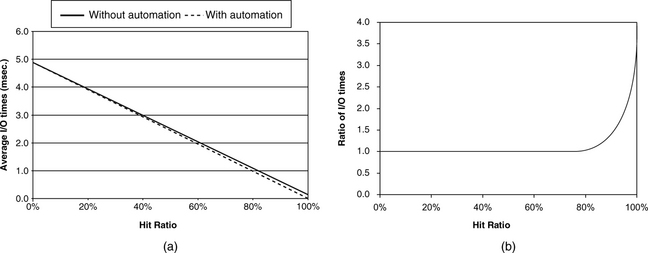
In some disk drives, hardware is used to automate the entire process of cache lookup and handling those I/O requests that can be satisfied from the cache. The result is that the cache hit overhead is very small. This sounds good, since the previous 4-KB cache hit can now be completed in 0.05 ms if an overhead time of 0.01 msec is assumed. However, the overall effect to the disk drive’s performance for this hardware automation is somewhat less dramatic. This is because, for most workloads and applications, the cache miss ratio is relatively high, and so the overall performance of the drive is dominated by the cache miss service time. The miss ratio (hit ratio) is the percentage of I/Os that cannot (can) be serviced completely with the cache. The overall average I/O time is given by
hit ratio × avg. hit time + miss ratio × avg. miss time (EQ 22.1)
Using the above numbers from our example and assuming local access, Figure 22.1(a) plots the average I/O time with and without hardware automation for varying hit ratios, and Figure 22.1(b) shows their ratio. It is clear from Figure 22.1(a) that improving the hit ratio is much more important than having hardware automation to speed up the response time of I/Os that are cache hits in reducing the overall average I/O time. Not until the hit ratio is well above 80% does the effect of automation become observable, according to Figure 22.1(b). At 100% hit ratio, the difference is significant. This is the territory of sequential reads and cache writes, as will be discussed later.
22.1.3 Read Cache, Write Cache
Caching can be applied to both read access and write access. While the caching actions for reads and writes are different, their effects on the I/O time are the same when the transaction can be completed using the cache memory and not any disk media access.
Read Caching
All disk drives today perform read caching. A very small fraction of a disk drive’s data is replicated and stored in its cache memory. When a read command arrives at the disk drive, its cache memory is checked to see if it contains the data requested. If all the requested data can be found in the cache, then it is a full hit, and the command can be quickly serviced without involving any of the drive’s mechanical components. If only part of the requested data is found in the cache (this is called a partial hit or a partial miss), or if none is found in the cache, then it is necessary to go to the disk media to retrieve the missing data.
To have any measurable impact on a drive’s performance, the read cache must provide full hits a fairly good percentage of the time. That means its content should be holding data that the user has a good likelihood of requesting. Hence, one of the key elements in designing the disk cache is figuring out what data to place in the read cache so as to maximize this likelihood. Since the size of the disk cache is typically about 0.01% of the storage capacity of a drive, clearly, it will have no effect for completely random I/O requests. This would be the environment a drive operates in when used in a storage subsystem serving many users and applications. Fortunately, in many other environments the I/O request stream seen by the disk drive does exhibit locality of reference. Such an environment provides an opportunity for the cache to produce the maximum beneficial effect. Temporal locality means a recently used piece of data will likely be accessed again in the near future. Spatial locality means neighboring data of a recently used piece of data will likely be accessed soon. Thus, caching algorithms, to be discussed later, are all about identifying the cache data with locality of access and retaining them.
Write Caching
Write caching operates on a completely different mechanism than read caching. With write caching, the drive controller services a write request by transferring the write data from the host to the drive’s cache memory and then reports back to the host that the write is “done,” even though the data has not yet been written to the disk media. (Data not yet written out to disk is referred to as “dirty”). Thus, the service time for a cached write is about the same as that for a read cache hit, involving only some drive controller overhead and electronic data transfer time but no mechanical time. Clearly, unlike read caching, write caching does not depend on having the right data content in the cache memory; write caching will always work, i.e., a write command will always be a cache hit, as long as there is available space in the cache memory. When the cache becomes full, some or all of the dirty data is written out to the disk media to free up space. This process is commonly referred to as destage.
Ideally, destage should be done while the drive is idle so that it does not affect the servicing of users’ requests. However, this may not always be possible. The drive may be operating in a high-usage system with little idle time ever, or the writes oftentimes arrive in bursts that quickly fill up the limited memory space of the cache. When destage must take place while the drive is busy, such activity adds to the load of the drive at that time, and a user will notice a longer response time for his requests. Instead of providing the full benefit of cache hits, write caching in this case merely delays the disk writes. However, even in this scenario, write caching still provides some performance benefits:
Scheduling of Queued Writes Because disks can often have multiple writes outstanding in the cache, these writes can be destaged using one of the scheduling algorithms discussed in Chapter 21. This reduces the total amount of time the drive gets tied up doing these writes compared to executing the writes as they arrive and in the order of their arrival. Even if the drive’s interface does not support command queueing, write caching is a de facto form of command queueing for writes. If the drive’s interface does support command queueing, write caching effectively increases the queue depth available for sorting by the number of writes that have been cached, making more choices available and thus enhancing performance. For example, if a disk drive can support up to 32 cached writes, it allows a non-queueing drive to behave like a queueing drive with a queue depth of 32 for write commands, and it increases the queue depth of a queueing drive by up to 32.
Write Avoidance In many environments, the same data may get updated multiple times within a relatively short period of time. One common example is someone working on a document and saving it periodically. If a new write arrives before the previous one has a chance to be destaged, that previous write no longer needs to be destaged. Therefore, with write caching, the total number of actual writes to the disk may be fewer than the total number of write commands received by the drive. This means less total work needs to be done by the drive.
Because cached write data is not written out to disk immediately, and because, so far, all disk drives use as cache memory DRAM, which is volatile, there is a chance that cached write data may be lost. This happens when the drive loses power before it is able to destage all the write data, such as an improper powering down of the drive or some sudden interruption in the system’s power supply. Thus, write caching should only be used for those applications that find such occasional loss of data tolerable. For those applications requiring high data integrity from disk storage, the drive must run with its write cache disabled, forfeiting the performance benefit of write caching. For those applications that are in between, with some data that need integrity guarantee while loss of other data is acceptable, two options permit them to run with write caching enabled, both of which are available in the SCSI and the ATA standard interfaces. These two options are the following:
• Flush A Flush command can be issued by the host, instructing the drive to immediately destage all outstanding cached writes. This method is used by various journaling and logging systems to guarantee data consistency while taking advantage of write caching.
• FUA An individual write command can have the Force Unit Access (FUA) option selected which informs the drive that this write must not be cached, but written to the disk directly. This permits the host application to control what critical data to bypass the write cache.
Read Caching in the Presence of a Write Cache
There are several things that can be done to improve the performance of reads when the disk cache does both read caching and write caching.
Read hits in write cache If a drive does write caching, the write cache should also be checked for possible read hits. While the probability of getting a hit there is usually small and is highly workload dependent, the cost for checking is basically free.
Read priority over destage Obviously, a read miss should be serviced first over any write cache destage. A delay in handling a read request that is a cache miss is directly observable by the user. The effect of delay in destaging is less directly observable.
One cache memory space The cache memory spaces should not be divided to have one part permanently dedicated for reading only and a second part for writing only. Having such a fixed partitioning of read cache and write cache is inefficient use of the cache space. It prevents the cache from dynamically adjusting itself to handle workload bursts dominated by either reads or writes. A good cache architecture should allow more space to be used for reads when there are more read commands in the workload that the drive is handling, and vice-versa.
Use same allocation space Taking the above concept one step further, a good cache architecture should allow cached write data and cached read data of the same LBA to use the same cache memory space. More specifically, if an LBA already exists in the cache from some prior disk read, a new write command using that same LBA should have its data stored into the same cache location. An organization that requires separate read and write cache spaces would have to allocate new write space to hold this new write data and invalidate the read cache space holding the old read data. This is inefficient use of cache space and creates unnecessary work for the drive controller.
22.2 Cache Organizations
The disk drive’s cache evolved from a humble beginning. Understandably, its data structures were fairly simple when initially developed, as the typical cache size was quite small. Some of those early simple designs have been carried over from generation to generation and are still used by today’s disk drives. One of these simple structures is actually assumed in the SCSI standard.
When some piece of disk data is to be stored in the disk cache, the cache space allocated to it is commonly called a cache segment, notionally equivalent to a solid-state cache block. Cache segments can be either fixed size or variable size. All the data stored within a segment is logically contiguous. When an I/O request arrives at the disk drive, the cache is checked to see if a segment has already been allocated for the LBAs of the request. If such a segment exists, then that segment will be used for the request. If no such segment exists, then a new segment will be assigned. If a segment contains some but not all of the requested LBAs, there are two choices: expand that segment if it is possible to do so or assign a new and different segment. After the cache’s initial startup period, to assign, or allocate, a new segment means that one or more existing segments must first be deallocated. When a segment is deallocated, association with its previously assigned LBAs is removed, and the data of those LBAs will be overwritten in the cache by new data.
22.2.1 Desirable Features of Cache Organization
The disk cache memory space is relatively small, so it is important to use it efficiently. The more user data that can be stored in the cache, the more likely a read request can get a cache hit out of it. A good cache organization should have the following features:
High space utilization Cache space allocation should not result in lots of wasted space. This may seem obvious, but if a relatively large-size cache allows for only a limited number of segments, then each segment may be much bigger than what is required to hold the data.
Single copy of data There should not be more than one copy of data for any LBA in the cache. This is a generalization of the shared memory space between the reads and writes concept discussed in the previous section. Again, this may seem obvious, but in practice it does happen with a number of cache organizations that the same LBA can appear in multiple segments. A cache organization allowing such duplication must ensure correctness of behavior, and the wasted space should be the cost of increased performance (e.g., similar duplication is possible in trace caches—see “Another Dynamic Cache Block: Trace Caches” was dicussed in Chapter 2, Section 2.6.3).
One cache memory space The cache space should not be partitioned into a read cache and a write cache, as discussed in the previous section.
Ease of allocation Finding space for a new segment should be a simple task, as it is part of the overhead for handling a command and affects the command’s response time.
In this section, the basic structures of three main classes of organization will be discussed. They are the segmentation, circular buffer, and virtual memory schemes.
22.2.2 Fixed Segmentation
The most common disk cache architecture is the fixed-segmentation scheme. With this organization, the cache memory space is divided equally into fixed-size segments, as illustrated in Figure 22.2. For example, an 8-MB cache with 16 segments will have 500 KB (one thousand 512 byte sectors) per segment. The number of segments may be fixed in a disk drive. Alternatively, since SCSI assumes drives to have such a cache organization, a host system can specify to an SCSI drive the number of segments that it wishes the drive to have.
Associated with the segments is a segment table, with each table entry corresponding to one segment. A segment table entry contains the starting LBA of the data block allocated to that segment and the number of sectors of that block currently stored in the segment. The entry also contains a flag indicating whether the segment’s data is dirty. Cache lookup is performed by searching through the segment table.
Because the segments are of fixed and equal size, a segment’s number can be used as the index for calculating the memory address of the segment:
seg. address = start address of cache + seg. no. × seg.size (EQ 22.2)
With respect to the list of desirable features listed in Section 22.2.1, the fixed-segmentation scheme has the following properties:
• Because the fixed-size segments are usually quite large, with space typically for hundreds of sectors, they are not very efficient for caching small blocks of data.
• Depending on the implementation, it is possible to have multiple copies of the same data in the cache. As a simple example, a command causes a segment to be created for LBAs 1000–1300. Later, another request for LBAs 900–1100 arrives. Since LBAs 900–999 are not in the cache, it is a partial miss. Because LBA 1000 starts at the beginning of the segment, there is no room in the segment to put LBAs 900–999, and so a new segment is allocated for the new command. For simplicity, the implementation chooses to load LBAs 900–1100 all in from the disk to the new segment. Now, two different segments contain LBAs 1000–1100.
• Generally, with the segmentation organization, segments created to handle write commands are distinct from segments created for read commands. However, any segment can be allocated for either read or write. Thus, there is no requirement for permanent partitioning of read cache space and write cache space, unless the designer chooses to for some other reasons.
• Typically, the segments are arranged in an LRU (Least Recently Used) list. When a segment is first assigned, or when there is a cache hit on an existing segment, that segment becomes MRU (Most Recently Used) and gets moved to the bottom of the LRU list.2 If a new segment is required for a new command, the segment at the top of the LRU list is deallocated and assigned to be the new segment. Hence, space allocation is a very simple procedure.
22.2.3 Circular Buffer
Another cache organization that dates back to the early days of disk cache is the circular buffer. In this architecture, the cache memory space is managed circularly. This means that when the last physical address of the cache memory space is reached, the hardware wraps the address around back to the beginning, as illustrated in Figure 22.3.
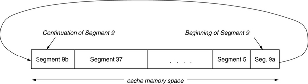
FIGURE 22.3 Cache memory space organization of the circular buffer scheme. Variable size segments are allocated from the buffer.
Thus, the cache, or buffer, space becomes a ring with no beginning or end. The operation of the circular buffer, also called ring, organization is described here in the context of the desirable features listed in Section 22.2.1.
• In the circular buffer organization, variable size segments are allocated. As a new command arrives and a new segment is needed (cache miss), contiguous cache memory space, just enough to service the command (including any prefetching), is allocated. Since only the required amount of data is allocated each time, space utilization can be quite efficient.
• Other than the segment size being variable, a circular buffer segment does not look that different from a segment of a fixed-size segmentation scheme. A segment of both schemes consists of physically contiguous memory space, and there are no rules or restrictions on the placement of LBAs within a segment (the virtual memory scheme is different in this respect). Thus, it is also possible here for an LBA to appear more than once in the cache.
• It is also not necessary for a circular buffer organization to have dedicated read cache and write cache partitioning. A newly created segment at any memory location can be used for either reading or writing.
• Looking for the necessary amount of contiguous memory space to create a segment is a more complex job here than the segmentation scheme. It is further complicated by the fact that write segments are intermixed with read segments, and a write segment cannot be deallocated without first destaging its data. Thus, ideally, one would prefer to look for read segments to deallocate first, using write segments as a last resort. Two main selection options are the classical best fit or first fit strategies. Best fit has better space utilization, but requires more search overhead.
A circular buffer organization also requires a segment table. In addition to information about what LBAs have been assigned to each segment, the segment’s starting cache memory address and its length must also be part of each segment entry, since that information can no longer be computed. Cache lookup is performed by searching through the segment table.
22.2.4 Virtual Memory Organization
The fixed-segmentation scheme is easy to manage, but not very space efficient. The circular buffer scheme is space efficient, but harder to manage. A scheme that combines the best of those two worlds is the virtual memory organization, which borrows from the general-purpose world and adapts the base mechanism to the disk drive—just as with virtual memory within the operating system, the virtual memory disk cache organization is a software implementation of a fully associative cache. Different variations of caching schemes based on the virtual memory concept are possible; the following discussion is but one example.
In the virtual memory scheme, the cache memory space is partitioned into N pages, which are the allocation units. The size of a page is 2M disk sectors, where M is a design parameter that governs the efficiency of space utilization. A smaller value of M allows more precise space allocation, but it incurs greater management overhead, so it is a design trade-off. For an 8-MB cache, if M = 5, then each page will hold thirty-two 512-B sectors or 16 KB of data, and there will be N = 512 pages. By choosing a reasonably small value of M, the virtual memory scheme can have equal or better space utilization as the circular buffer with variable segment size. In the following, M = 5 is used as the example for all discussions.
Logical Segment
Each segment can consist of one or more pages. Therefore, there can be up to N segments in the cache. While the contents of the pages within a segment are logically contiguous, the pages themselves do not have to be physically contiguous in memory. In other words, physically non-contiguous pages are mapped to form a logically contiguous segment. The physically non-contiguous pages of a segment form a logical chain. For example, pages 35, 101, and 8 can be the pages of a segment allocated to LBAs 19200–19295, with page 35 holding LBAs 19200–19231, page 101 holding LBAs 19232–19263, and page 8 holding LBAs 19264–19295. Since the contents of pages 35, 101, and 8 are logically contiguous, they form a logical chain. This flexibility of being able to dynamically create logical chains using non-contiguous pages simplifies the search for space to form a new segment of any length.
All the pages can be arranged in some replacement list, such as LRU, similar to the segmentation scheme, for the purpose of allocation. A page can be used for either read data or write data or both. Associated with each page is a Dirty Flag; this flag is set if the page contains one or more dirty sectors, i.e., sectors with cached write data that needs to be written out to disk. When the drive decides that K pages need to be allocated for a new segment, it simply takes the first K units that do not have the Dirty Flag set from the top of the LRU list.
LBA Mapping
An LBA of the disk drive is divided into L upper bits and M lower bits, as shown in Figure 22.4. The L upper bits together form the tag of the LBA. All the 2M LBAs having the same tag form an allocation group. Sectors belonging to the same allocation group are stored together in the same page. When a sector of an allocation group is stored in a page, the M lower bits of its LBA are used as the index into the page to determine its location within that page. Thus, the LBA with the lower bits 00000 will be stored in the first sector location of a page, 00001 will be stored in the second sector location, 00010 will be stored in the third sector location, …, and 11111 will be stored in the last sector location.

If an LBA already exists in some page, that page will be used for that LBA, and no new page will be assigned. Furthermore, new write data will be placed right over previous read/write data of the same LBA if it exists in the cache. Hence, no more than one page will ever be assigned to the same LBA, and an LBA will never have more than one occurrence in the cache. This is one of the desirable features of a cache organization.
Hashing
While it is certainly possible to do cache lookup by sequentially examining the content of each page, this can be a slow process, and it is much faster to use a hashing technique instead. A simple hash function is applied on the K upper bits, or tag, of an LBA to generate a hash number with H bits. Any hashing function can be used; it can be as simple as taking the lower H bits of the tag. All 2M LBAs in the same allocation group will generate the same hash since they all have the same M upper bits (tag). Additionally, K is usually greater than H, thus many allocation groups, in fact 2K–H of them, will also have the same hash; the hash is a many-to-one mapping. When two pages are allocated to tags which have the same hash, the condition is known as collision. Handling of collision is discussed below.
There is a hash table with 2H entries. Each hash table entry contains a pointer to a page containing an allocation group whose hash is the offset (entry number) of this entry in the hash table. See Figure 22.5. This pointer is the head pointer for a hash chain (see later). If no allocation unit is associated with this hash table entry, then the entry contains a NULL pointer.

Page Table
In addition to a segment table, there is a page table,3 with each entry corresponding to one page. Each entry contains:
1. The tag of the LBAs of the allocation group assigned to this page.
2. A valid data bit map of 2M bits corresponding to the sectors in the page. A bit is set if valid data is present for the corresponding sector.
3. A dirty data bit map of 2M bits. A bit is set if the data for the corresponding sector is dirty. This bit map constitutes the Dirty Flag mentioned earlier.
4. A hash chain pointer. As pointed out earlier, multiple allocation groups have the same hash. This pointer points to the next page whose allocation group has the same hash number as this page. The last page in the chain has a NULL for this pointer to indicate the end of chain.
Cache Lookup Procedure
To determine if an LBA exists in the cache, the tag field of that LBA is used to generate a hash. This hash number is used to index into the hash table, as illustrated in Figure 22.5. If that entry in the hash table is NULL, then the LBA does not exist in the cache. If the hash entry points to a page table entry, the tag field of that entry is compared with the tag of this LBA. If they match, then the page containing this LBA is found. If they do not match, then the hash chain pointer of the page table entry is used to locate the next entry, and the comparison is repeated for the next entry. The hash chain is thus followed until either a match is found and the page containing this LBA is located or the end of chain is reached in which case the LBA is not in the cache.
If a section containing the LBA being searched is located in the cache, its valid bit map can be examined to see if the bit corresponding to this LBA is set. If it is set, then valid data for this LBA is in the cache, and it is a cache hit. The page number and the lower M bits of the LBA completely determine the physical address of the sector in the cache memory space.
Attributes of Architecture
It should be clear from the foregoing discussions that a cache architecture based on the virtual memory concept can possess all the desirable features of a cache organization listed in Section 22.2.1. Because the pages, which are the allocation units, are typically of relatively small granularity, space utilization is very efficient. As explained in the LBA mapping, read and write data share the same space, further enhancing space utilization efficiency. Finally, because non-contiguous pages can easily be stitched together to form a logical chain of any length, space management is a simple task.
22.3 Caching Algorithms
While the cache organization defines how the address space of cache memory is to be structured and managed, another equally important aspect of cache design has to do with how the cache is to be utilized to provide good performance.
As mentioned earlier, write commands can always be cached as long as there is available space in the cache. Thus, good handling of write caching is mainly issues of using the write cache space efficiently and timely destaging of cached writes to make room for new write requests. Segmentation is a poor utilization of cache space, especially for small random writes where write caching provides the biggest benefit. Therefore, it is not a good cache design choice if the disk cache supports write caching. Schemes such as the circular buffer, which allows segment size to match exactly the write request size, or the virtual memory organization, which allows a fine granularity of allocation unit size, are much more suitable for supporting write caching.
Unlike writes, a read command is a full cache hit if, and only if, all the data it requests is already in the cache. So the focus of this chapter is on cache handling for reads. In Section 22.1.1, it was explained that the benefit provided by a disk cache mainly comes from data prefetch, as the much larger cache in the host and/or storage subsystem controller generally filters out the majority of requests that are for data reuse. Thus, the emphasis of disk cache algorithms is mainly on data prefetching.
22.3.1 Perspective of Prefetch
The ultimate goal for a disk cache is to maximize the percentage of cache hits for any workload to which it is applied. When the hit ratio is maximized, disk media accesses and, hence, mechanical times will be minimized, leading to shorter average I/O time and higher throughput. With respect to prefetch, there are a couple of principles for achieving the ultimate goal:
1. Bring as much useful data into the cache as possible at as little cost as possible.
2. Retain as much data brought in as possible and for as long as possible.
Prefetch is an exercise in speculation. There is no guarantee that prefetched data will ever get used. Yet, prefetch is not free; it requires the disk drive’s resources (disk arm, read/write electronics, etc.) to bring the prefetch data into the cache, thus tying up the drive and preventing it from doing other work. So, if there is a user request waiting while prefetch is ongoing, the user request gets delayed, and the user sees an increased response time. Therefore, a common strategy is not to start any prefetch if there are I/O requests waiting to be serviced. Along the same line of reasoning, another common strategy is to preempt, or terminate, any ongoing prefetch as soon as a new I/O request arrives. One exception to this rule is when the new request happens to be a cache hit and therefore can be fully serviced from the cache alone without requiring the other disk resources that are being used in prefetching.
Another cost of data prefetching is that prefetched data takes up space in the cache. In order to provide space for the prefetched data, some other data already in the cache will have to be displaced, which is against the second principle cited previously. If data that is not to be used in the near future is brought into the cache and results in throwing out some useful data from the cache, the situation is referred to as cache pollution. The net effect is negative for future performance.
The host system can, and oftentimes does, initiate data prefetching. The argument for the drive to initiate its own prefetch is that the drive knows when it can do prefetch without interfering with normal requests. On the other hand, one of the reasons why data prefetched by the drive does not always get used is that today’s drive has no file system knowledge of the data that it stores. Thus, the data that the drive prefetches is usually only based on the principle of locality of access, which is a probabilistic rather than a deterministic thing. One possible remedy to this situation is for the host to provide hints to the drive on what it should and should not prefetch. Also, there are proposals to turn the drive into an object-based storage device (OSD) by migrating part of the file system from the host down to the disk drive, but these are only just proposals at this time.
22.3.2 Lookahead Prefetch
The most common type of prefetch is known as look-ahead. This is prefetching for data that immediately follows the data requested by a user. For example, if a user requests LBAs 1000–1100, lookahead prefetch would be for data from LBA 1101 to 1100 + M, where M is some maximum prefetch limit set by the drive controller. There are two reasons why lookahead prefetch is a good strategy and is adopted by all disk drives:
1. Due to spatial locality of access, there is generally a good probability that lookahead data may be requested soon. For example, the initial request may be for the first sheet of a spreadsheet. When the user goes to the second sheet, which presumably is stored on disk right after the first sheet, then its I/O request will be for the lookahead data of the first request. Therefore, in many cases, lookahead data satisfies the “usefulness” criterion of the first principle of Section 22.3.1.
2. For the drive to do lookahead prefetch, it only needs to continue reading from the disk after retrieving the block requested by the user. There is no seek or latency involved. Thus, it satisfies the “low cost” criterion of the first principle of Section 22.3.1.
Determining the amount of data to prefetch is a difficult design choice. As pointed out earlier, one of the costs of prefetching is the cache space that prefetched data takes up. As a general rule, the farther away a piece of data is from the current data, the less likely it is that that data would have any correlation with the current data and, hence, the lower the probability that it will be used in the near future. Therefore, bringing too much data in during prefetch, even when the drive is otherwise idle, can pollute the cache and hurt performance. There is no single correct choice, since the correct choice is really workload dependent and varies from application to application.
22.3.3 Look-behind Prefetch
Another type of prefetch, which is becoming almost as common as lookahead, is known as look-behind. As its name implies, this is prefetching for data that immediately precedes the data requested by a user. Using the previous example where a user requests LBAs 1000–1100, look-behind prefetch would be for data from LBA 1000 – N to 999, where N is some maximum prefetch limit set by the drive controller.
The backward referencing of preceding data occurs less commonly than forward referencing, but it does occur in real-life applications. Therefore, look-behind prefetching is not as useful as lookahead prefetching, but it is still useful.
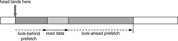
To keep the cost of look-behind prefetching low, it is common practice to do such prefetching only during the rotational latency time of a read. It prefetches only as much data as it can read, or less, during this latency period, as illustrated in Figure 22.6. If it happens to be just a few bytes, then so be it. A policy that imposes the drive to always prefetch a fixed amount or some minimum amount of look-behind data is counterproductive. To do so would force the drive to wait extra time for the missed data if the head happens to land closer to the requested data than the desired look-behind prefetch amount. This significantly increases the cost of prefetch for data that only has a moderate-to-low probability of use.
22.3.4 Zero Latency Prefetch
In Chapter 21, Section 21.1.3, the technique of zero latency access was introduced, which improves the performance of accessing requested data by reducing the net effective rotational latency. This same technique can be extended in an obvious manner to cover the case of data prefetching. Consider the case where the head lands on the track after the requested data, somewhere in the middle of the lookahead prefetch area. Figure 22.7(a) shows the common practice where the drive will stay on the track and wait for the beginning of the requested data to come around, doing look-behind prefetch before that as just described above. After the requested data has been read, then the drive continues to do lookahead prefetch as described in Section 22.3.2, taking more than one disk revolution to finish the data read, lookahead prefetch, and look-behind prefetch processes. On the other hand, Figure 22.7b shows the operation of zero latency access in the prefetch area. The drive starts reading immediately the very next sector encountered on arrival in the middle of the lookahead prefetch area. It reads until the end of the maximum prefetch limit and then waits for the beginning of the requested data to come around, prefetching look-behind data in the process. After the requested data has been read, then the drive continues to complete the lookahead prefetch, stopping just before the first sector where reading started. Thus, the data read, lookahead prefetch, and look-behind prefetch processes together take roughly one disk revolution.

22.3.5 ERP During Prefetch
Chapter 18, Section 18.9.3, describes recovering a non-correctable read error by retrying to read the sector multiple times, perhaps with different head offsets and read channel parameters. Each retry takes one full revolution of the disk, and hence the ERP (error-recovery procedure) can take a very long time to complete. Furthermore, error recovery is not always successful. Since prefetched data may not actually get used, it does not make sense to spend a lot of time doing ERP when a non-correctable error is encountered during prefetch. The drive controller should either terminate the prefetch completely or skip over the defective sector if it is possible to mark the data for that sector invalid in the cache.
22.3.6 Handling of Sequential Access
The importance of sequential accesses was pointed out in Chapter 19, Section 19.1.1: if handled properly, sequential access can be completed faster than non-sequential accesses by more than an order of magnitude. Proper prefetching for such data is extremely important; if sequential or skip-sequential data is not ready and waiting in the cache when a request for those data come, then the drive will have to wait (usually the better part of one disk revolution) to read the data off the disk.
There are four aspects of handling prefetch for sequential accesses that need to be pointed out.
Sequential detect The drive controller should monitor the I/O requests arriving to detect those I/Os that are part of a sequential pattern. It should be able to identify not only straightly sequential requests that are back to back, but also near-sequential and skip-sequential accesses (see Chapter 19, Section 19.1.1, for definitions).
Prefetch extension When a prefetch is first initiated, the drive controller usually establishes an upper bound of how much data to prefetch. If, while prefetch is still ongoing, new I/O requests arrive that are hits in this prefetch segment, i.e., some type of sequential hits, then it makes sense to extend the amount of data to be prefetched. At a minimum, one should reset the upper bound LBA using the same maximum amount starting from the current hit location. For example, if the maximum prefetch amount is 200 sectors, and the current prefetch is for LBAs 1001–1200, then a hit in LBA 1050 will cause the prefetch range to be extended to LBA 1250.
Minimum prefetch In Section 22.3.1, it was discussed that a common strategy is to immediately terminate an ongoing prefetch if a new command that requires accessing the disk media is received. While, in general, that is a policy that makes good sense, if the prefetch happens to be initiated by an I/O which is detected to be part of a series of sequential accesses, then the probability that the prefetched data will get used becomes very high. In this case, it makes sense to prefetch some minimum amount of data before allowing the prefetch to be preempted. The size of the minimum prefetch is a design parameter. Ideally, it should be adaptively determined by the drive controller, based on the number of I/Os in the sequential series that the drive has seen so far and the requested block size, with the minimum amount proportional to both of these two measurements.
Space allocation Data accessed in a long sequential series is generally not likely to be re-read again in the near future. In other words, such data, once consumed, is no longer useful. Therefore, when allocating space for prefetch extension, it is best to reallocate the space for the sequential data that has just been consumed. A common technique is to use the current segment circularly. If attention is not paid to this aspect of sequential access, the entire content of a cache can be completely wiped out by a long sequential series.
22.3.7 Replacement Policies
When a new segment needs to be allocated for the servicing of a new command, one or more existing segments must first be deallocated so that their spaces can be used. Determining which segment to discard is an important part of caching, since removing data that will soon be used instead of data that will not be used any time soon is obviously detrimental to the performance of the drive. The rules that the drive controller follows in choosing what data to discard is called the replacement policy.
The most common cache replacement policies include first-in-first-out (FIFO), least-recently-used (LRU),4 and least-frequently-used (LFU). None of these policies in their purest form are ideally suited for disk cache application. FIFO is probably no better than random selection in choosing the least likely to be used data for replacement. LRU is appropriate for most applications, as it is basically based on the principle of temporal locality of access which does occur in those applications. One very major exception is with sequential accesses, as discussed previously in Section 22.3.5. If LRU is followed strictly, then recently consumed sequential data, while no longer useful, will stay in the cache for a long time before it finally becomes least-recently-used. Thus, if LRU is to be used, at the minimum, modification needs to be made to recognize that sequential data should be detected and not be promoted to be most-recently-used. LFU is good for keeping certain regularly used data, such as the root directory of a file system, in the cache. However, without some modification, it would not be very effective in handling data references due to locality of access. For these reasons, a good cache replacement policy usually involves some combinations of common strategies for achieving better cache performance.
1Ideally, though, in general, the net data rate is slightly below the interface speed due to various low-level interface overheads.
2Variations to this simple strategy can be made, but the discussion is beyond the scope of this book.
3Actually, the segment table can be dispensed with by incorporating the segment information into the page table.
4Also called Most-recently-used (MRU).