Media: Wireless, Fiber and Unshielded Twisted Pair Copper
Media (copper, coaxial cable, fiber optics and airwaves) carry voice and data traffic. Characteristics of media have a direct bearing on the speed, accuracy and distance at which traffic can be carried. For example, thin copper lines carry data more slowly than thicker, higher quality copper. Fiber carries vastly more traffic than copper. It is used for high-speed Internet and public switched telephone networks.
Unshielded twisted pair (copper) is the most prevalent medium used to link computers to corporate printers and applications. It also is used to connect telephones to PBXs and key systems. Fiber in enterprise sites is generally used in high-traffic areas such as connections between buildings and floors.
Because it is a nonelectric medium, fiber exhibits superior performance. In contrast to copper, it does not act like an antenna that picks up noise and interference. New electronics in fiber optic networks are improving fiber's performance. These systems that improve the capacity of fiber are called wavelength division multiplexing (WDM) or dense wavelength division multiplexing (DWDM).
Wireless is starting to be used to link staff to corporate LANs. LANs connect PCs and devices within buildings for access to email, printers and shared applications. A key attraction of wireless media is the mobility it provides. For example, wireless LANs enable people to use laptops or handheld computers in any location within range of antennas. Prices for wireless LANs are decreasing and interest in using them is increasing. Wireless services including LANs, cellular network and wireless local loops obviate the need to lay expensive cabling. This is particularly important in developing and emerging markets around the world where most of the populations do not have landline telephones.
Wireless as a way to provide local service is called wireless local loop (WLL). XO Communications, Sprint and WorldCom sell WLL services. They offer high-speed voice and data connections to commercial buildings in metropolitan areas. Wireless as a medium for local telephone service is discussed in Chapter 4. Cellular service is covered in Chapter 9.
Wireless LANs
Organizations install wireless LANs for the following reasons:
The difficulty of pulling wires in existing buildings. Specialized applications such as engineering and software development often require a second non-Microsoft computer at users' desks. This might require running more cabling.
Staff's need to use computers in common areas such as conference rooms, training rooms and cafeterias.
The miniaturization of devices such as laptops and handheld computers that users want to take with them to meetings and training sessions, where there might not be sufficient cabling to accommodate everyone in the area.
Reliance on corporate servers for shared documents (groupware) such as Lotus Notes and intranets requires that people take their laptops with them to meetings, so they can access corporate data wirelessly.
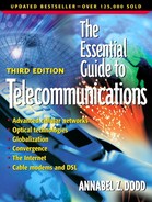
New wireless LANs work on the Ethernet 802.11b IEEE-specified standard known as Wi-Fi (short for wireless fidelity). The agreement by manufacturers to adhere to this standard has resulted in the availability of off-the-shelf, lower cost products. Network interface cards (NICs) that plug into the PCMCIA slot of laptops have dropped from $300 to $150. This is still higher than NICs for wired LANs that typically cost $50. Base stations with antennas are integrated with bridges or routers and are wired to the LAN. See Figure 2.15. The bridges and routers provide communications to corporate files and devices on the LAN. Base stations are called access points and cost about $1000. (See Chapter 1 for bridges and routers.) Wireless LAN manufacturers are: Cisco, through its purchase of Aironet, Agere Systems (formerly part of Lucent Technologies), 3Com, Nokia and Ericsson.
Figure 2.15. Conference room within range of the wireless LAN.

In addition to price, security issues hamper Wi-Fi-based LAN sales. In 2001, researchers at the University of California, Intel Corporation and the University of Maryland all reported on security flaws in the 802.11b standard. The flaw is serious and lets people eavesdrop on corporate networks and even get email addresses of legitimate users from which they can forge their own address. Products currently on the market to improve the 802.11b security also are reported to have serious flaws. A special industry task force has already begun circulating draft revisions of new security standards. Products based on new security standards are expected to be available in 2002.
The top speed on 802.11b LANs is 11 million bits per second. This is adequate for most nonmultimedia, engineering and imaging applications. However, speeds can degrade as users get farther away from base stations, and interference from metal in floors or doors can degrade service. New 802.11g and 802.11a standards are expected, which will increase the capacity and speeds of wireless LANs. 802.11g-compatible products are expected by 2002, and 802.11a-compatible products are expected by year-end 2001.
Wireless LAN Connections in Public Places
Wireless LANs based on Wi-Fi are being installed in public places, such as coffee shops (Starbucks), airports and hotels. People who sign up for this service with Internet service providers, such as Wayport, can use their laptop computer to access the Internet and email messages from these locations. The 802.11b wireless LAN installed in the coffee shop or airport is connected to the Internet via a high-speed connection, for instance, a T-1 line. Subscribers need an 802.11b wireless LAN card. They also must sign up for Internet service from an ISP who arranges for connectivity to the Internet from the airport or coffee shop. After it leaves the public place, the data is carried over landline-based networks. The traffic is not transmitted on cellular networks.
Electrical Properties of Copper Cabling
The electrical properties of copper cabling create resistance and interference. Signals weaken the farther they are transmitted on copper wires. The electrical property of copper cabling is the key factor that limits its transmission speeds.
Signals sent over copper wire are, for the most part, direct-current electrical signals. Signals near these wires can introduce interference and noise into the transmission. In particular, copiers, magnetic sources, manufacturing devices and radio stations all can introduce noise. It is not uncommon for office and residential users to complain that they can hear a nearby radio station's programming on their telephone calls. This is the result of interference.
Within homes and businesses, crosstalk is another example of “leaking” electrical transmissions. In homes with two lines, a person speaking on one line often can hear the faint conversation on the other line. Current from one pair of wires has “leaked” into the other wire. One way in which copper cabling is protected from crosstalk and noise introduced from nearby wires is by twisting each copper wire of a two-wire pair. Noise induced into each wire of the twisted pair is canceled at the twist in the wire. Twisted pair copper cabling is used from:
Telephone sets to PBX common equipment
Telephone sets to key systems common equipment
PCs to the wiring closet of a LAN
Homes to the nearest telephone company equipment
Category 5 Unshielded Twisted Pair—Cat 5
Unshielded twisted pair copper cabling is used to connect individual telephones and PCs to in-building telephone systems and local area networks. Organizations often install category 5 cabling for both voice and data rather than paying technicians to lay one set of cables for data and another set for voice.
Twisted pair cabling and connection components used inside buildings are rated by the Electronics Industry Association/Telecommunications Industry Association (EIA/TIA). In 1992, standards were published for category 5 unshielded twisted pair for data transmitted within buildings at 100 megabits per second (Mbps). Category 5 is the most common twisted pair cabling used within buildings for data. The standard refers to not only the cable but to all of the connections including jacks, plugs and cross connects in wiring closets. Cross connects in wiring closets tie all of a floor or section of a floor's cabling to cabling that runs between floors in the risers. Category 5 is commonly referred to as cat 5. Category 3 unshielded twisted pair is rated as suitable for voice transmission.
Category 6 Unshielded Twisted Pair
Category 6 cabling capable of carrying data at gigabit speed is now available. However, the International Standards Organization/International Electrotechnical Commission (ISO/IEC) has draft specifications for category 6 but has not yet approved the standards. Category 6 cabling requires cables, jacks, and wiring closet connectors to all meet the specifications for category 6 for gigabit speeds. Two problems exist with category 6 cabling: Without standards, customers cannot mix and match cabling from one manufacturer with plugs and RJ-45 jacks [registered jacks for data with connections for eight (four pairs) wires] from other manufacturers. The same applies to wiring closet connectors. The second problem is that customers who plug category 6 cabling into category 5 jacks might not even achieve category 5 performance because of electrical mismatches between the two standards.
Cable currently on the market has the same weight as category 5; however, it is manufactured under more strict guidelines. In essence, it is tested more precisely for characteristics such as near- and far-end crosstalk and jitter. Jitter is caused by uneven electrical or mechanical changes. It results in “bumpy” or disruptive transmissions.
Category 6 cable also is referred to as category 5 – level 7 cabling. Standards boards also are considering category 7 standards for even higher performance for twisted pair copper cabling.
Fiber Optic Cabling—High Capacity and High Costs
Fiber optic cabling is immune to electrical interference. Signals are transmitted in the form of off and on light pulses similar to a flashlight. No electricity is present in transmissions over fiber. Thus, signals carried on strands of fiber do not interfere with each other. Therefore, fiber can be run in areas without regard to interference from electrical equipment. Other benefits of fiber are:
Security— Fiber is resistant to taps and does not emit electromagnetic signals; therefore, to tap into fiber strands, the strands have to be physically broken and listening devices spliced into the break. These splices are easily detected.
Small size— Less duct space is required; individual strands of fiber are the diameter of a length of hair. Duct size is particularly significant under city streets where underground conduit is at capacity, filled with old copper cabling.
High bandwidth— Fiber is suitable for new high-speed transmission services such as terabit routers.
Low attenuation— There is less fading or weakening of signals over distances, which means fewer amplifiers are needed to boost the signals.
The absence of sparking hazards in flammable areas results in less danger of fire.
Single conductor fiber weighs nine times less than coaxial cable.
Disadvantages of fiber optic cabling include:
Termination, component and connector costs are higher than for copper wiring. Specialized equipment is required to terminate fiber cables within buildings, test and splice fiber and to convert electrical signals to light pulses and vice versa.
More care in handling fiber is needed. In particular, fiber is not as flexible as twisted pair in bending around corners.
When fiber is brought into buildings from telephone companies or to the curb in residential areas, local electrical power is required. This adds a point of vulnerability in the event of a power outage.
Specialized technicians, who might be paid at higher levels, often are required to work with and test fiber cabling.
According to Corning Incorporated's Just the Facts (p. 2, July 1995):
The first practical fiber systems were deployed by the telephone industry back in 1977 and consisted of multimode fiber. Single-mode fiber, a more recent development was first installed by MCI in a long-haul system that went into service in 1983.
Instead of using wide-diameter conduit (pipes) to carry fat lengths of copper or coaxial cabling between buildings or floors, organizations lay thin strands of fiber optic cabling capable of transporting vast amounts of voice and data between buildings or floors within a building.
Individual organizations often use fiber cabling:
For the riser, between floors within a building portion of their networks (see Figure 2.16.) The extra expense of laying fiber, however, is usually not justified to individual users and devices on LANs.
Figure 2.16. Unshielded twisted pair and fiber optic cabling within a building.

In campus environments, for cable runs between buildings.
Many long distance networks are completely fiber. Fiber's greater capacity and higher speeds justifies the added expense. Telephone companies use fiber because they can lay fewer strands of fiber in less space than heavier copper, which requires many more pairs to achieve the same capacity as fiber optic cabling. Moreover, signals can travel farther, in the range of 60 miles, on fiber without the use of amplifiers to strengthen a faded signal. The requirement for fewer amplifiers translates into lower maintenance costs: There are fewer amplifiers to break down.
Other places fiber is used are:
Between central offices in local telephone company networks
From local and long distance phone companies to office buildings
Between central offices and neighborhood wire centers
In Internet service provider networks
In the backbone of cellular networks
Between cellular networks and landline networks
For undersea cable runs between continents
In backbone cable TV (CATV) networks (between the cable company headbands and neighborhood coaxial cable wire centers); see Figure 2.17
Figure 2.17. Hybrid fiber coaxial (HFC) cabling for cable TV networks.
In electric utility networks
Fiber optic cabling is made of ultrapure strands of glass. It carries on and off light pulses over the central core of the fiber. The more narrow the core, the faster and farther a light signal can travel without errors and repeaters. The cladding surrounding the core keeps the light contained within the core to prevent the light signal from dispersing, that is, spreading and losing strength. Finally, there is a coating, which protects the fiber from environmental hazards such as rain, dust, scratches and snow.
Single-Mode Fiber—Smaller Is Faster and More Expensive
There are two different types of fiber: single-mode and multimode. Single-mode fiber is smaller, more expensive and supports faster speeds than multimode fiber. Single-mode fiber is the diameter of a strand of hair. Telephone companies, cable companies, ISPs and transoceanic cabling use the more expensive, higher capacity, single-mode fiber optic cabling.
The fact that single-mode fiber carries light pulses faster than multimode fiber can be explained by the geometric rule: A straight line is the shortest distance between two points.
If a person sticks to a straight line over the course of a race, she will get to the end of the race faster than if she zigzagged along the track. Similarly, the small core of the fiber keeps the light signal from bouncing across the diameter of the core of the fiber. Thus, the light signal travels faster than if it had a more “bouncy” ride through the core. Because it travels in a straighter line, the light pulses go farther without attenuation, or weakening. Thus, fewer repeaters are needed to boost the signal. Single-mode fiber can be run for 60 miles without the use of a repeater. In contrast, copper cabling needs to be repeated after approximately 1.5 miles. This is the reason telephone companies use fiber in residential areas with cable runs longer than 2 kilometers, or 1.24 miles.
The main factor in the increased expense of single-mode fiber is the cost of splicing and connecting it to patch panels and other devices. The core is so small that connections and splices need to be done in a more exacting manner than with multimode fiber. If fiber connections on single-mode fiber do not match cores exactly, the light will not be transmitted from one fiber to another. It will leak or disperse out of the core at the splice.
Multimode fiber is used mainly for LAN backbones between buildings on campuses and between floors of buildings.
Dense Wavelength Division Multiplexing (DWDM)
The importance of dense wavelength division multiplexing (DWDM), also called wavelength division multiplexing (WDM), cannot be exaggerated. It is a key technology for providing the capacity to carry traffic associated with applications such as e-commerce, multimedia email, voice over IP (VOIP) and World Wide Web browsing. It is an important part of the infrastructure for voice, high-speed data, streaming video and streaming audio. (See Chapter 1 for an explanation of streaming media.)
DWDM provides the following advantages:
Higher capacity over fewer strands of fiber
Lower costs to upgrade networks, because multiplexed speeds up to 10 gigabits per channel can be achieved by changing electronics but reusing old fiber cabling (newer fiber supports higher speeds)
Space savings in service providers' networks because less amplifying equipment is required
Lower ongoing maintenance expenses in carriers' networks because less equipment is required
DWDM technology provides long distance networks with immense improvements in capacity. It is a multiplexing technique that enables single strands of fiber to carry multiple channels of voice and data. Early implementations of wavelength division multiplexing (WDM) carried eight channels over a single strand of fiber. By the end of 1998, DWDM multiplexers carried 40 channels at 2.5 gigabits per channel. Capacity is expected to reach 200 channels at 10 gigabits per channel on a single strand of fiber by year-end 2001. This equals 2000 gigabits (billions of bits per second), or 2 terabits per second. These four-fold increases in the number of wavelengths and the speed of each wavelength cost only two and a half times as much as the previous DWDM systems. Thus the cost per unit of bandwidth decreases.
Dense wavelength division multiplexers work like prisms, separating out colors into different beams that are carried on the fiber. WDM divides the light stream into multiple frequencies called colors. Each color or shade is carried at a different frequency. (See Chapter 1 for an explanation of frequencies.) The individual wavelengths also are called lambdas.
Wavelength Division Multiplexing (WDM) Components
Connecting fiber to copper lines requires converters called transmitters and receivers to convert electrical signals to light pulses. Transmitters also are called light source transducers. Transmitters in fiber optic systems are either light-emitting diodes (LEDs), or lasers. Lasers are more expensive than LEDs but they provide more power so that the light signals need less amplification, or boosting, over long distance. One laser is required per wavelength. LEDs are commonly used with multimode fiber.
At the receiving end, the light detector transducers (receivers) that change light pulses into electrical signals are either positive intrinsic negatives (PINs) or avalanche photodiodes (APDs). LEDs and PINs are used in applications with lower bandwidth and shorter distance requirements. Once a length of fiber is in place, upgrades in multiplexing technology enable the embedded fiber to carry information at higher speeds. The multiplexers enable gigabit speeds and multiple applications to share fiber strands.
Amplifiers and Regenerators
Amplifiers and multiplexers are key components of DWDM networks. Amplifiers boost the signals and multiplexers combine light from multiple sources onto a single strand of fiber.
Optical amplifiers are spaced approximately 60 miles apart from each other. The amplifier boosts the signal, which loses strength as it travels over distances. (In a voice conversation, voice signals sound softer when they lose strength and need to be amplified.) They were first installed in 1990. Prior to that, optical signals first had to be converted back to electrical signals to be regenerated. Without optical amplifiers, both regenerators and multiplexers are required every 30 miles. This results in more expensive equipment in the network and more space needed in network-based equipment huts. Now optical amplifiers only are required every 60 miles.
Regenerators are placed approximately every 1500 miles. They multiplex (combine) and demultiplex (separate out) the optical signals. The signals are converted from optical to electrical signals for functions such as electrical clocking, noise removal, and error checking. The multiplexers concatenate the signals, a technical term for putting the signals into the correct sequence.
The increased capacity of DWDM is one factor in the bandwidth glut that now exists in carriers' backbone, city-to-city networks. The benefit is that prices on these routes are continuing to decline.