
For users working in a studio with a separate recording booth and control room, Cubase 6 provides the Control Room Mixer panel, which provides additional routing possibilities. The Control Room Mixer is fully customizable and supports up to four separate studio cue mixes, four separate monitor mixes, six external inputs, one control room headphone mix, and a talkback channel to communicate instructions to musicians from the control room without having to walk over to the booth or yell your lungs out.
For project studio producers, the Control Room Mixer and its studio connections, combined with multi-I/O audio hardware for use with Cubase, provide a flexible monitoring system without having to use an external mixer.
Creating the studio connections is discussed in Chapter 4, “Monitoring and Connecting Audio.” This chapter discusses some of the applications and benefits associated with the Control Room Mixer panel and its Control Room Overview panel.
Here’s a summary of what you will learn in this chapter:
How the Control Room Mixer settings are represented in the Control Room
Overview
How to configure and monitor external input busses
How to Control Room–monitoring options
How to use the Listen Enable bus functionality
How to use the Control Room’s Talkback functionality
How to use the Dim button and Use Reference Level button
How to display the Control Room Mixer Extended panel
How to add inserts to Control Room busses
How to use studio sends to create discrete mixes
Before I begin discussing Control Room features, here are a few beginning pointers:
If you are monitoring through an external mixer, you probably don’t need to enable the Control Room Mixer (CRM) features. You can disable the Control Room functionalities by clicking on the Disable Control Room button in the Studio tab of the VST Connections window. Settings that are in effect when the CRM is disabled will be reestablished once it is enabled again.
To avoid any routing confusion when using the Control Room Mixer, set all output busses to Not Connected or set the VST Mixer’s main stereo output to act as the main mix on the CRM. You will be controlling what you hear in the control room through the CRM instead, which will provide you with additional monitoring and routing functionalities. Cubase displays the main stereo output bus corresponding to the CRM’s main mix with a red speaker icon next to the connection’s name in the VST Connections window. Right-click (PC)/Control-click (Mac) in the right column for another bus in the Outputs tab of the VST Connections panel, and select the Set <This Output’s Name> as Main Mix option if you ever need to use that bus as the main mix.
Like Cubase’s Mixer panel, the CRM adapts itself to the connections created in the VST Connections panel. If you create a talkback connection, it will be available, but if you don’t create one, those features will not be visible.
In Cubase, the same audio ports can be used for different input and output busses, depending on your requirements at a given phase in the project. However, audio inputs and outputs used for studio connections can’t be used for anything else. Once a port has been assigned to a studio connection, consider it unavailable for other uses. That’s why you need an audio hardware device with multiple inputs and outputs to fully take advantage of the CRM features. There are a few exceptions to this rule. Using the same speakers in a stereo configuration and also in a surround configuration, with the same outputs on the audio hardware assigned to both monitor configurations is one of those exceptions. Sharing the inputs between an input bus and an external input device is another exception in which using the same ports for both purposes makes sense when creating connections.
Here’s a typical project studio example in which the CRM comes in handy. Let’s say that you’re recording guitar and vocal overdub tracks over a stereo mix of a groove a friend has sent over the Internet, and you’ve already loaded the audio mix in a track. You’re the guitarist, and you need to hear this mix along with a click track, but the vocalist wants to hear the mix without the click. The guitar is connected to an external preamp, which feeds an input on the audio interface. The lead singer’s microphone is also connected to an external preamp feeding another input.
Because this is a project studio, I’ll assume everyone is in the same room, so monitoring is done through headphones during recording. You’ll need the following connections:
Two mono input busses—one for the guitar and another for the vocals.
One monitor connection to connect two audio output (stereo) ports on your audio hardware to control room monitors in the studio. Click the Monitor switch in the Control Room Mixer, as shown in Figure 6.1, to switch between the two sets of monitors at any point in time.
One headphone connection for the guitarist/producer. (To create headphone or cue mixes for musicians in different recording booths, use the studio channels described later.)
One studio channel for an independent vocal headphone mixes. (The vocalist doesn’t want to hear the click track.)

To work with the Control Room function, you need to display both the Control Room Mixer and Control Room Overview (CRO) panels; you enable both these panels from Cubase’s Devices window. Both of these panels are shown in Figure 6.2; on the left is the CRO panel, and the CRM is on the right side of the figure.

Figure 6.2. Example of a typical project studio Control Room setup, as viewed through the CRO and CRM panels.
Let’s look at the CRO panel from top to bottom and describe what’s happening. The CRO displays all the external inputs and studio, monitor, and talkback connections available. When a connection has been created, the CRO displays it in a darker shade. The channel mixer is summed and sent to the active “studios.”
In the CRM, this channel is represented by the first channel on the left, labeled as “Studio 1.” The Mix button at the top of this channel also indicates that the signal monitored through this channel comes from the main mix. The CLIK (Activate Metronome Click) button in the center of the channel enables the metronome click for this channel. In the CRO, this is represented by the small white square below the active studios channel. You get the same result in the CRO by enabling the CLIK button in this channel or clicking to enable the corresponding small square button (labeled “click”) where the metronome line meets the studios line will offer the same result. (When the click is activated, the box turns green.)
Moving along to the headphones at the bottom of the CRO display, in the second channel to the left of the CRM (labeled Phones), you can see that it also monitors the main mix, but in this example, the CLIK button is enabled in both locations (the CRO and the CRM).
At the top of each CRM channel is the Input Selector button, which controls the source of the audio signal entering each channel. When an external input is created, an additional EXT button shows up at the top. If more than one external input is created, you can click on the Show Left Strip button to expand the CRM’s left strip, which reveals an external input selection.
There is also a similar strip on the right of the CRM that offers a number of monitoring options, which vary depending on the studio connections you have created (from top to bottom in Figure 6.3):

Click on any speaker to mute all other speakers. (In a 5.1 surround configuration, the plus sign in the center allows you to solo the LFE channel.)
Click on Cancel Speaker Solo to unmute all channels at once. There are also a number of additional solo functions, depending on the active monitoring setup.
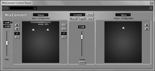
Click any down-mix preset buttons to automatically switch between different down-mix options. A down-mix option lets you hear different mixes through the same monitors. For example, clicking on a stereo mix while monitoring in surround lets you hear how your surround mix will translate to stereo; clicking on a mono mix for a stereo recording lets you hear how your stereo recording will sound in a monophonic environment. Clicking on the Open MixConvert Settings down arrow opens the settings panel for the MixConvert plug-in, shown in Figure 6.4, where you can change the down-mix configuration if necessary.
The Cycle Downmix Preset button lets you quickly cycle through all the preset down-mixes.
The CRM’s Listen mode lets you send the signal of all audio-related Mixer channels that have their Listen buttons enabled to the Control Room monitors without interrupting the signal flow, overriding the normal signal being monitored. On many hardware consoles, this is also called the Pre Fader Listen (PFL) bus, because the levels that will be heard are unaffected by that channel’s main volume fader. The Listen mode bypasses the Mixer’s Volume Level control, the studio monitoring options, and the metronome options. When enabled, the signal is routed to this bus directly after the signal enters the channel, before any phase, trim, inserts, EQ, volume, or pan controls.
The CRM’s Talkback mono connection provides a way to communicate with musicians in a different room through a studio connection by connecting a microphone to one of the input ports on your audio hardware and creating a talkback connection in the VST Connections panel. Talkback options are displayed in the CRM only when a talkback channel has been created in the Studio tab of the VST Connections panel.
The Dim button lets you quickly reduce the Control Room level by 30 dB without having to change the fader’s position, which makes it very convenient when the producer wants to comment on a recording or mixing pass, and you want to make sure you heard the comments properly. Click the Dim button again to return the control room level to where it was. You can change the actual amount of reduction applied by the Dim button in the Preferences dialog box, on the Control Room panel.
The reference level lets you set the Control Room monitoring level to a calibrated mix, essential to most film-dubbing stages. By default, this value is set to –20 dB, but you can change this value by setting the Control Room fader to a new level and holding down the Alt (PC)/Option (Mac) key when clicking on the Reference Level button. When the reference level is used, the button is lit.
You can add insert effects to all channels found in the CRM as well as display output level metering through the CRM’s extended view. Click the Show Extended Panel button, as shown in Figure 6.5, to display this panel. The Show Meters button toggles the display between inserts and output level meters.

As you can see, all channels can have up to six pre-fader inserts and, with the exception of external inserts and monitors, they also can have two additional post-fader inserts (numbers 7 and 8). By default, the external input inserts are displayed, but you also can add inserts to the talkback connection. To do so, simply enable the Talk button. Cubase displays the talkback inserts where the external input inserts are currently displayed. The talkback connection can have up to eight inserts.
You will find more on using insert effects in Chapter 13, “Using Insert Effects,” but understand that you can use dynamic inserts, such as a gate or compressor, on the talkback connection, for example, to protect your performers’ ears or to reduce the noise level leaking when talkback is enabled, or to add some reverb to the mix sent to the singer in the example I described at the beginning of this chapter.
Studio sends are intended as discrete mixes that can be used to send a customized headphone mix through a studio connection. By creating a mix using studio sends, you can make sure the bass player hears the kick drum well without forcing the singer or pianist to hear the same mix. Like many functionalities available in the CRM, the number of studio sends available is tied to the number of studio connections you created, so you can have up to four studio send mixes or four discrete headphone mixes. The way studio sends work is very similar to the way FX channels work. However, FX channels are better suited to process audio being sent from a number of audio or instrument channels (with a reverb or delay send effect on one of their inserts, for example) and can be used outside the CRM. You’ll find more on FX channel tracks in Chapter 33, “Working with FX Channel Tracks.”
Set up a discrete mix using studio sends
In the Mixer panel (F3), display the extended panel.
In the extended panel’s common area, click on the Show Studio Sends button. The studio sends controls will appear as shown in Figure 6.6.
Enable the studio sends for each channel you want to include in the mix.
Set the amount of signal sent from the channel to the studio connection by dragging the horizontal line displayed under the level value. You also can Alt-click (PC)/Option-click (Mac) on the value to use the pop-up fader.
Adjust the panning of the signal in the mix. As with the volume level, the pan value only affects the studio send mix.
By default, studio sends are set to Post-Fader, but to change the studio send level setting to Pre-Fader (so that its level will not be affected by changes to the channel’s main volume fader), enable the option.
In the CRM, set the studio connection’s source to AUX. From this point on, all signals being sent to studio sends 1 will be heard through the studio 1 connection.
