
Chapter 8. Video Displays and Graphics Cards
This chapter covers a portion of the CompTIA A+ 220-701 objectives 1.7 and 1.9, and CompTIA A+ 220-702 objectives 1.1 and 1.2.
The monitor and video card work together as the display subsystem to provide real-time notification of the computer’s activities to the user. Because you might spend all day (and sometimes all night) gazing into the display, keeping it working to full efficiency is important. This chapter helps you prepare for the A+ Certification Exams by enhancing your understanding of the major types of video cards and displays and showing you how to configure and troubleshoot them.
“Do I Know This Already?” Quiz
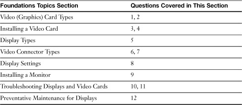
The “Do I Know This Already?” quiz allows you to assess whether you should read this entire chapter or simply jump to the “Exam Preparation Tasks” section for review. If you are in doubt, read the entire chapter. Table 8-1 outlines the major headings in this chapter and the corresponding “Do I Know This Already?” quiz questions. You can find the answers in Appendix A, “Answers to the ‘Do I Know This Already?’ Quizzes and Troubleshooting Scenarios.”
Table 8-1 “Do I Know This Already?” Foundation Topics Section-to-Question Mapping
1. Which of the following bus types are used for video cards? (Choose all that apply.)
a. PCI
b. AGP
c. DMI
d. PCI Express
2. Which of the following are used to keep the video card cool? (Choose all that apply.)
a. Passive heat sinks
b. Thermal glue
c. Cooling fans
d. Shrouds
3. When installing a new video card, there are three phases. What are they? Select the best three answers.
a. Configuring the BIOS for the video card being installed.
b. Physically installing the video card.
c. Making sure the video card is in the protective anti-static bag.
d. Installing drivers for the video card.
4. You install a new video card in your system, but are not getting all the features. What would you need to do to correct the problem?
a. Reboot the computer
b. Install the device driver
c. Take the card out and put it back in
d. Call a technician
5. What are three major types of display devices that are in use in today’s industry? (Choose all that apply.)
a. CRT monitors
b. LCD monitors
c. Data projectors
d. USB monitors
6. Identify three types of video connectors.
a. VGA type
b. DMI type
c. HDMI type
d. USB type
7. If you are installing a new LCD monitor, what current standard port will you need for digital signals?
a. LCD monitor
b. AGP slot
c. A DVI port on the video card
d. A VGA video port
8. Where would you go to set your display resolution in Windows XP?
a. My Computer
b. Display Properties
c. Screen Saver tab
d. Appearance tab
9. When installing a new monitor, what should you do first? (Choose the best answer.)
a. Determine what type of cable is compatible with your video card
b. Go to the advanced dialog screen and choose a resolution
c. Connect the cable to the video card
d. None of these options is correct
10. If the colors are flickering on your monitor, what could be the problem?
a. Refresh rate too slow
b. Refresh rate too fast
c. Loose video cable
d. The monitor is bad
11. If your monitor has low contrast and brightness, what might you do to correct the problem?
a. Change the refresh rate
b. Re-install the monitor
c. Check the connection
d. Use the OSD buttons on the front of the monitor
12. Which of the following steps should you take when maintaining monitors? (Choose all that apply.)
a. Do not block ventilation holes in CRT and LCD displays.
b. Use antistatic cleaners made for electronics to clean screens and other surfaces.
c. Do not spray cleaners directly onto screens or enclosures.
d. Use thumbscrews to hold VGA and DVI cables in place on displays, projectors, and video cards.
e. When a system is opened for upgrades or service, check the condition of the cooling features of the video card. Remove hair, dust, or dirt in or on the heat sink, cooling fan, fan shroud, or heat pipe radiator. Make sure airflow around and behind the video card is not obstructed by cables, dirt, dust, or other components.
f. Allow plenty of clearance around the video card slot. Don’t use the slot next to the video card if the card would limit airflow to the video card’s cooling features.
Foundation Topics
Video (Graphics) Card Types
The video card (also known as the graphics card or graphics accelerator card) is an add-on card (or circuit on the motherboard of portable computers and some desktop computers) that creates the image you see on the monitor. No video card means no picture.
Currently, video cards use the following bus types:
• PCI
• AGP
• PCI Express (PCIe)
Many low-cost desktop systems use integrated video instead of a video card, although many recent desktops also include a PCIe slot. For more information about these expansion slot standards, see the section “Expansion Slots,” in Chapter 3, “Motherboards, Processors, and Adapter Cards.”
In the mid 1990s, the most common type of expansion slot used for video cards was PCI. Although PCI is still the leading general-purpose expansion slot type, the advent of the Pentium II CPU led to the development of the Accelerated Graphics Port (AGP) expansion slot, which is dedicated solely to high-speed video.
AGP slots have largely been replaced in recent systems by PCI Express x16 slots. Many recent high-performance systems feature two PCI Express x16 slots that support either the NVIDIA-developed SLI or the ATI-developed CrossFire technologies for rendering 3D scenes on one video card with two (or more) graphics processing units (GPUs), or two video cards that work in unison; a GPU is the graphics processing chip on a video card. To see a typical motherboard that supports NVIDIA’s SLI, refer to Figure 3-1 in Chapter 3.
Video Card Cooling
All video cards contain a component called the graphics processing unit (GPU). The GPU is used to render information on its way to the display, and especially when performing 3D rendering, it can become very hot. Memory chips on the video card can also become very hot. Consequently both the GPU and memory require cooling.
Cooling can be provided through passive heat sinks or through cooling fans and fan shrouds as shown in Figure 8-1. Passive heat sinks on older video cards typically cover only the GPU, but newer ones provide cooling for both the GPU and memory. Video cards with passive heat sinks are good choices for home theater PCs, such as those running Windows XP Media Center Edition or Windows Vista Home Premium or Ultimate, because these PCs need to run as quietly as possible.
Figure 8-1 This AMD FireMV 2260 video card for technical workstations uses a passive heat sink to cool the GPU and memory. Photo courtesy of AMD.

![]()
Note
Some video cards use a variation of passive heat sinks known as cooling pipes. Cooling pipes use pipes to route heat from the GPU and memory to a radiator-type passive cooler on the card. A cooling pipe cooler provides better cooling than a standard passive heat sink, but requires extra space around the video card.
The video card shown in Figure 8-2 uses a fan and a fan shroud to cool the GPU and memory. Some low-performance video cards that use a fan for cooling the GPU don’t use a fan shroud, relying on case fans to cool video card memory.
Figure 8-2 This AMD ATI HD3870 video card includes a high-performance fan cooler and shroud over the GPU and memory to dissipate heat. Photo courtesy of AMD.

![]()
Installing a Video Card
The installation process for a video card includes three phases:
Step 1. Configuring the BIOS for the video card being installed
Step 2. Physically installing the video card
Step 3. Installing drivers for the video card
BIOS Configuration
The BIOS settings involving the video card might include some or all of the following, depending upon the video card type:
• AGP speed settings— Found in systems with an AGP slot. Most systems automatically detect the type of AGP card installed (2x, 4x, or 8x) and configure speed settings accordingly. However, you can override the settings if necessary. For example, enable AGP Fast Write to improve graphics performance, but disable it if the system crashes.
• Primary VGA BIOS (also known as Primary Graphics Adapter)— Set this to AGP or AGP->PCI if you use a AGP video card; PCIE or PCIE->PCI if you use a PCI Express video card. Use PCI, PCI->PCIE or PCI->AGP if you use a PCI video card. For onboard video, see the manufacturer’s recommendation (onboard video can use PCI, AGP, or PCI Express buses built into the motherboard).
• Graphics aperture size— Found in systems with an AGP slot. Use the default size, which is typically the same as the amount of memory on the AGP card.
Adjust these settings as needed.
Video Card Physical and Driver Installation
Although all video cards created since the beginning of the 1990s are based on VGA, virtually every one uses a unique chipset that requires special software drivers to control acceleration features (faster onscreen video), color depth, and resolution. So, whenever you change video cards, you must change video driver software as well. Otherwise, Windows will drop into a low-resolution, ugly 16-color mode and give you an error message because the driver doesn’t match the video card.
Here’s how to replace a video card (or upgrade from integrated video to a video card) and install the drivers in Windows 2000/XP/Vista:
Step 1. Go into Device Manager and delete the listing for the current graphics card.
Step 2. Shut down the system and unplug it.
Step 3. Turn off the monitor.
Step 4. Disconnect the data cable attached to the video card.
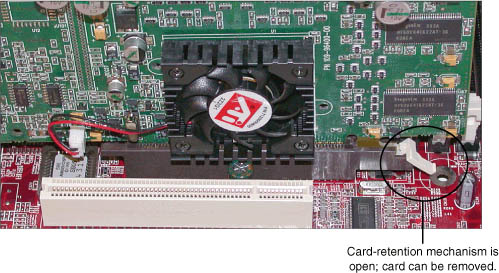
Step 5. Open the case and remove the old video card. Remove the screw holding the card bracket in place, and release the card-retention mechanism that holds an AGP or PCI Express video card in place (refer to Figure 8-3).
Figure 8-3 Releasing the card-retention mechanism before removing an AGP video card.
Note
Card-retention mechanisms vary widely from motherboard to motherboard. In addition to the design shown in Figure 8-3, some use a lever that can be pushed to one side to release the lock, while others use a knob that is pulled out to release the lock.
Step 6. Insert the new video card. Lock the card into position with the card retention mechanism (if you are installing an AGP or PCI Express card) and with the screw for the card bracket.
Step 7. Reattach the data cable from the monitor to the new video card. If you are connecting a monitor with a VGA cable to a video card that uses only DVI-I ports (refer to Figure 8-2), attach an adapter between the DVI-I port and the VGA connector (see Figure 8-4).
Figure 8-4 Using a DVI-I/VGA adapter.

Step 8. Turn on the monitor.
Step 9. Turn on the computer and press F8 to display the startup menu.
Step 10. Select Enable VGA Mode from the startup menu.
Step 11. Provide video drivers as requested; you might need to run an installer program for the drivers.
Step 12. If the monitor is not detected as a Plug and Play monitor but as a Default monitor, install a driver for the monitor. A driver disc might have been packed with the monitor, or you might need to download a driver from the monitor vendor’s website. If you do not install a driver for a monitor identified as a Default monitor, you will not be able to choose from the full range of resolutions and refresh rates the monitor actually supports.
To learn more about connector types used by monitors and video cards, see the section “Video Connector Types,” later in this chapter.
Display Types
There are three major types of displays you need to understand for the A+ Certification exams:
The following sections help you understand the common and unique features of each.
CRT Monitor
Cathode ray tube (CRT) displays are now fading in popularity but are still in widespread use on older systems. CRTs use a picture tube that is similar to the picture tube in a tube-based TV set. The narrow end of the tube contains an electron gun that projects three electron beams (red, blue, green) toward the wide end, which is coated with phosphors that glow when they are hit by the electron beams. Just before the phosphor coating, a metal plate called a shadow mask is used to divide the image created by the electron guns into red, green, and blue pixels or stripes that form the image. Shadow masks use one of three technologies:
• A phosphor triad (a group of three phosphors—red, green, and blue). The distance between each triad is called the dot pitch.
• An aperture grill, which uses vertical red, green, and blue phosphor strips. The distance between each group is called the stripe pitch.
• A slotted mask, which uses small blocks of red, green, and blue phosphor strips. The distance between each horizontal group is also called stripe pitch.
If you look closely at a CRT display, you can see the individual triads or strips. However, from normal viewing distances, they blend into a clear picture.
Figure 8-5 shows the design of a typical CRT monitor.
Figure 8-5 A cutaway of a typical CRT display.

Generally, the smaller the dot or stripe pitch, the clearer and sharper the onscreen image will be. Typical standards for CRT monitors call for a dot pitch of .28 millimeters (mm) or smaller. Generally, low-cost monitors have poorer picture quality than higher-cost monitors of the same size because of wider dot pitch, low refresh rates at their highest resolutions, and poor focus at their highest resolutions.
Typical CRT displays range in size from 15 inches (diagonal measure) to 19 inches, and feature support for a wide range of resolutions. CRTs are analog display devices that can display an unlimited range of colors, and use the 15-pin VGA connector. To learn more about VGA connectors, see the section “VGA,” later in this chapter.
LCD Monitor
LCD displays use liquid crystal cells to polarize light passing through the display to create the image shown on the monitor. In color LCD displays, liquid crystal cells are grouped into three cells for each pixel: one each for red, green, and blue light.
All LCD displays use active matrix technology, which uses a transistor to control each cell, as the basic technology. Variations in how quickly a display can refresh, how wide the viewing angle, and how bright the display help distinguish different brands and models from each other.
An LCD monitor is a digital design, but many models, particularly low-end models and older designs, use the same VGA analog interface as CRTs. In such cases, the monitor must include an analog-digital converter to change the analog signal received by the VGA cable into a digital signal. High-end LCD displays and most recent midrange models also support digital signals and use DVI-D ports. To learn more about active-matrix displays, see “LCD Screen Technologies,” in Chapter 9, “Laptops and Portable PCs and Components.” To learn more about DVI-D connectors, see the section “DVI,” later in this chapter.
Compared to CRT monitors, LCDs are much lighter, require much less power, emit less heat, and use much less desk space.
An LCD display has only one native resolution; it must scale lower resolutions to fit the panel, or, depending upon the options configured in the video card driver, might use only a portion of the display when a lower resolution is selected. When a lower resolution is scaled, the display is less sharp than when the native resolution is used.
LCD displays are found in both standard (4:3 or 1.33:1) and widescreen (16:9 or 16:10) aspect ratios, and range in size from 14 inches (diagonal measure) to 24 inches or larger.
Data Projector
Data projectors can be used in place of a primary display or can be used as a clone of the primary display to permit computer information and graphics to be displayed on a projection screen or a wall.
Data projectors use one of the following technologies:
• Liquid crystal display (LCD)
• Digital light processing (DLP)
LCD projectors use separate LCD panels for red, green, and blue light, and combine the separate images into a single RGB image for projection, using dichroic mirrors. A dichroic mirror reflects light in some wavelengths, while permitting light in other wavelengths to pass through. In Figure 8-6, red and blue dichroic mirrors are used to split the image into red, blue, and green wavelengths. After passing through the appropriate LCD, a dichroic combiner cube recombines the separate red, green, and blue images into a single RGB image for projection.
Figure 8-6 How a typical three-LCD data projector works.

LCD projectors use a relatively hot projection lamp, so LCD projectors include cooling fans that run both during projector operation and after the projector is turned off to cool down the lamp.
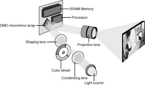
DLP projectors use a spinning wheel with red, green, and blue sections to add color data to light being reflected from an array of tiny mirrors known as a digital micromirror device (DMD). Each mirror corresponds to a pixel, and the mirrors reflect light toward or away from the projector optics. The spinning wheel might use only three segments (RGB), four segments (RGB+clear), or six segments (RGB+RGB). More segments helps improve picture quality. Figure 8-7 illustrates how a DLP projector works.
Figure 8-7 How a typical DLP projector works.
Video Connector Types
When selecting a monitor or projector for use with a particular video card or integrated video port, it’s helpful to understand the physical and feature differences between different video connector types, such as VGA, DVI, HDMI, Component/RGB, S-video, and composite.
VGA
VGA is an analog display standard. By varying the levels of red, green, or blue per dot (pixel) onscreen, a VGA port and monitor can display an unlimited number of colors. Practical color limits (if you call more than 16 million colors limiting) are based on the video card’s memory and the desired screen resolution.
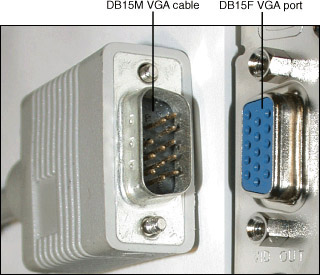
All VGA cards made for use with standard analog monitors use a DB-15F 15-pin female connector, which plugs into the DB-15M connector used by the VGA cable from the monitor. Figure 8-8 compares these connectors.
Figure 8-8 DB15M (cable) and DB15F (port) connectors used for VGA video signals.
![]()
DVI
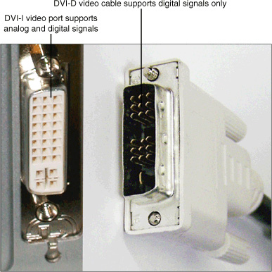
The DVI port is the current standard for digital LCD monitors. The DVI port comes in two forms: DVI-D supports only digital signals, and is found on digital LCD displays. Most of these displays also support analog video signals through separate VGA ports. However, video cards with DVI ports use the DVI-I version, which provides both digital and analog output and supports the use of a VGA/DVI-I adapter for use with analog displays (refer to Figure 8-4). Figure 8-9 illustrates a DVI-D cable and DVI-I port.
Figure 8-9 DVI-I video port and DVI-D video cable.
![]()
HDMI
Video cards and systems with integrated video that are designed for home theater use support a unique type of digital video standard known as High-Definition Multimedia Interface (HDMI). HDMI is unique in its ability to support digital audio as well as video through a single cable. HDMI ports are found on most late-model HDTVs as well as home theater hardware such as amplifiers and DVD players.
The most recent HDMI standard, version 1.3b, supports up to 1080p HDTV, 24-bit or greater color depths, and various types of uncompressed and compressed digital audio. However, all versions of HDMI use the cable shown in Figure 8-10 and the port shown in Figure 8-11.
Figure 8-10 HDMI cable (right) compared to DVI-D cable (left).
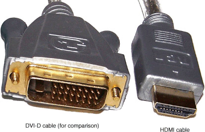
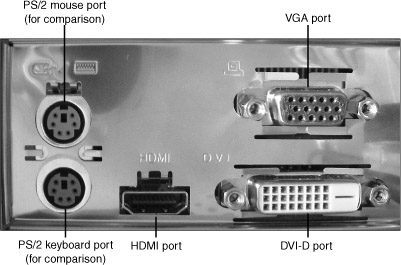
Figure 8-11 HDMI, DVI-D, and VGA ports on the rear of a typical PC built for use with Windows Media Center and home theater integration.
![]()
Systems and video cards with integrated HDMI ports might also feature DVI-I or VGA ports, as in Figure 8-11.
A converter cable with a DVI connector on one end and an HDMI connector on the other end can be used to interface a PC with an HDTV if the PC doesn’t have an HDMI port.
Component/RGB
Some data projectors and virtually all HDTVs support a high-resolution type of analog video known as component video. Component video uses separate RCA cables and ports to carry red, green, and blue signals, and can support up to 720p HDTV resolutions.
S-Video
S-video divides a video signal into separate luma and chroma signals, providing a better signal for use with standard TVs, projectors, DVD players, and VCRs than a composite signal. The so-called “TV-out” port on the back of many video cards is actually an S-video port (refer to Figure 8-1).
Composite
The lowest-quality video signal supported by PCs is composite video, which uses a single RCA cable and port to transmit a video signal. Video cards sold in Europe usually use a composite signal for their TV-out signal.
Composite video can be used by standard definition TVs (SDTVs) and VCRs. If you need to connect a PC with an S-video port to a TV or VCR that has a composite port, you can use an S-video to composite video adapter.
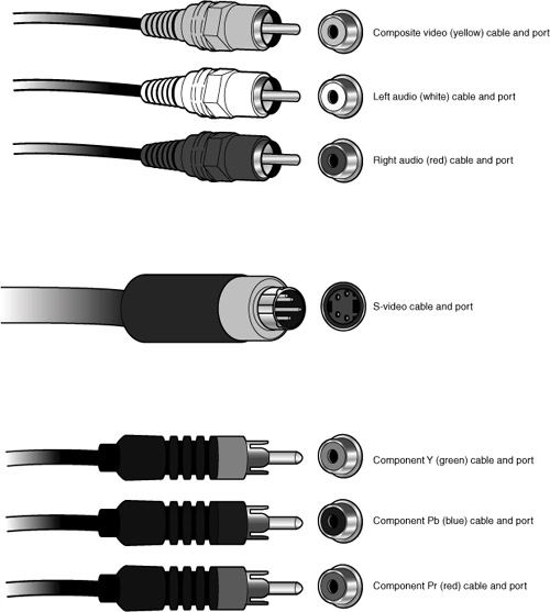
Figure 8-12 compares component, S-video, and composite video cables and ports to each other. Note that composite video cables are often bundled with stereo audio cables, but can also be purchased separately.
Figure 8-12 Composite video and stereo audio, S-video, and component video cables and ports compared.
![]()
Display Settings
Once a display is connected to your computer, it might need to be properly configured. The following sections discuss display settings issues you might encounter in A+ Certification exams.
Resolution
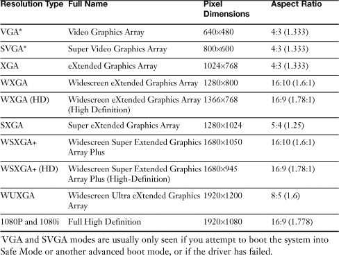
Display resolution is described as the amount of pixels (picture elements) on a screen. It is measured horizontally by vertically (HxV). The word resolution is somewhat of a misnomer, and will also be referred to as pixel dimensions. Table 8-2 shows some of the typical resolutions used in Windows. The more commonly used resolutions are in bold.
Table 8-2 List of Resolutions Used in Windows
To modify screen resolution do the following:
• In Windows Vista— Right-click the desktop and select Personalize. Then click the Display Settings link. Toward the bottom left of the window is a box called “Resolution,” which has a slider that enables you to configure the pixel dimensions.
• In Windows XP— Right-click the desktop and select Properties. Then click the Setting tab within the Display Properties window. Toward the bottom left of the window is a box called “Screen resolution,” which has a slider that enables you to configure the pixel dimensions.
These dialogs are also used to select color quality and to enable multiple displays on a system that supports two or more monitors (see Figure 8-13).
Figure 8-13 The Settings tab controls display resolution, multiple monitor support, color quality (color depth), and provides access to advanced settings.

![]()
Unless you need to select a lower resolution for specific purposes, you should select an LCD monitor’s native resolution (see the instruction manual or specification sheet for this information). For a CRT, choose a resolution that is comfortable to view and enables the monitor to run in a flicker-free refresh rate, ideally 75Hz or higher.
Color Quality (Color Depth)
Color quality (also known as color depth or bit depth) is a term used to describe the amount of bits that represent color. For example, 1-bit color is known as monochrome, those old screens with a black background and one color for the text, as in the classic movie War Games. But what is 1-bit? 1-bit in the binary numbering system means a binary number with one digit; this can be a zero or a one, a total of two values: usually black and white. This is defined in scientific notation as 21, (2 to the 1st power, which is 2). Another example would be 4-bit color, used by the ancient but awesome Commodore 64. In a 4-bit color system you can have 16 colors total. In this case 24 = 16.
Now that you know the basics, take a look at Table 8-3 which shows the different color depths used in Windows.
Table 8-3 List of Color Depths Used in Windows
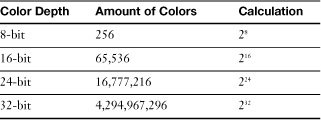
8-bit color is used in VGA mode, which is uncommon for normal use. But you might see it if you boot into Safe Mode, or other advanced modes that disable the video driver. 16-bit is usually enough for the average user who works with basic applications, however many computers are configured by default to 24-bit or 32-bit (also known as 3 bytes and 4 bytes respectively). Most users will not have a need for 32-bit color depth; in fact, it uses up video resources. If the user only works on basic applications, consider scaling them down to 24-bit or 16-bit in order to increase system performance. However, gamers, graphics artists, and other designers will probably want 32-bit color depth.
Note
Typically, only video cards or onboard video circuits that lack 3D support list 24-bit color as the best color quality option; systems and onboard video with 3D support list 32-bit color instead of 24-bit color as the best color quality option.
To modify color quality, do the following:
• In Windows Vista— Right-click the desktop and select Personalize. Then click the Display Settings link. A drop-down menu for color quality is located on the bottom right.
• In Windows XP— Right-click the desktop and select Properties. Then click the Setting tab within the Display Properties window. A drop-down menu for color quality is located on the bottom right.
Refresh Rates
The vertical refresh rate refers to how quickly the monitor redraws the screen and is measured in hertz (Hz), or times per second. Typical vertical refresh rates for CRT monitors vary from 56Hz to 85Hz or higher, with refresh rates of 75Hz causing less flicker onscreen.
Tip
Flicker-free (75Hz or higher) refresh rates are better for users running CRTs, producing less eyestrain and more comfort during long computing sessions. Note that LCD monitors never flicker, so the Windows default refresh rate of 60Hz works well with any LCD display.
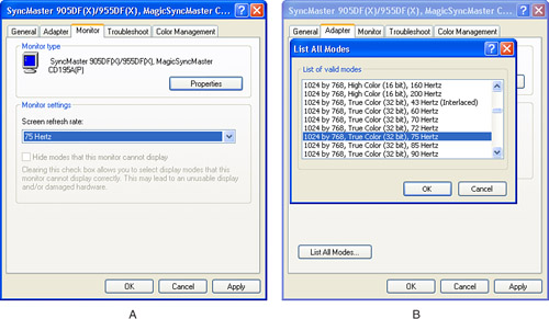
The vertical refresh in Windows can be adjusted through the Advanced portion of the Display Properties sheet. You can select a different vertical refresh rate in one of two ways:
Step 1. Select the Monitor dialog and choose a refresh rate from the Screen Refresh Rate dialog (Figure 8-14a).
Figure 8-14 Selecting the vertical refresh rate from the Monitor dialog (a) and from the Adapter dialog (b).
![]()
Step 2. Select the Adapter dialog, click List All Modes, and choose the combination of resolution, color depth, and refresh rate desired (Figure 8-14b).
Note
If your monitor is listed as Default monitor rather than Plug and Play monitor or as a specific monitor model, you will not be able to choose flicker-free refresh rates. Install a driver provided by the vendor.
Caution
Selecting a refresh rate that exceeds the monitor’s specifications can damage the monitor or cause the monitor to display a blank screen or a “signal out of range” error. If you select a refresh rate that exceeds the monitor’s specifications, press the ESC (Escape) key on the keyboard to return to the previous setting.
Installing a Monitor
To install a monitor in Windows, follow this procedure:
Step 1. Determine if the monitor is using a cable that is compatible with your video card. If you can change the cable, do so if necessary. In the case of an LCD display, you will have better picture quality if you use DVI rather than VGA interfacing.
Step 2. If the system is currently running, open the Advanced dialog and choose a resolution and refresh rate that are supported by both the current monitor and the new monitor, and then shut down the system.
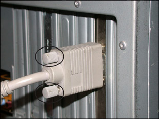
Step 3. Connect the cable between the monitor and the video card. Fasten the thumbscrews to hold the VGA or DVI cable in place (see Figure 8-15).
Figure 8-15 Fastening the video cable into place.
Step 4. Plug the monitor into an AC outlet, turn it on, and restart the computer.
Step 5. Open the Display properties sheet and select Settings (refer to Figure 8-13).
Step 6. If your monitor is listed as Plug and Play or by brand and model, adjust the resolution. If not, install a new driver for the monitor before continuing. The monitor driver might be provided on a CD, or you might need to download it.
Step 7. If you are installing a CRT display, open the Advanced dialog and choose an appropriate flicker-free refresh rate.
Troubleshooting Displays and Video Cards
Some problems with the display subsystem are caused by the video card, while others are caused by the monitor or projector, and still others might involve the Windows driver. Use the following sections to determine the causes and find solutions for common problems.
Troubleshooting Picture Quality Problems with OSD
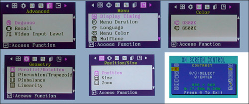
Picture quality problems of all types, ranging from barrel or pincushion distortion and color fringing on CRT monitors to picture size and centering, contrast and brightness on both CRT and LCD monitors, can be fixed by using onscreen picture controls, also known as the OSD. The OSD is controlled with push buttons on the front of both CRT and LCD displays, and provide a greater number of adjustments than older types of digital display controls.
Typical picture adjustments available on virtually all monitors include
• Horizontal picture size
• Horizontal picture centering
• Vertical picture size
• Vertical picture centering
• Contrast
• Brightness
CRT displays also offer settings for removing picture distortion, color balance, color temperature, degaussing (removes color fringing in a CRT display caused by the magnetic fields in the monitor), and options for the language and position of the onscreen display (OSD).
Figure 8-16 shows typical examples of OSDs for CRT and LCD monitors.
Figure 8-16 Typical OSD adjustments for CRT and LCD monitors. A portion of an LCD monitor’s OSD is shown in the inset at lower right; the other images are from a typical CRT’s OSD.
![]()
Figure 8-17 shows examples of barrel (outward curving image sides) and pincushion (inward curving image sides) distortion that can take place on CRT displays when different resolution settings or image-size adjustments are made. OSDs can adjust these picture geometry errors away as well.
Figure 8-17 Typical geometry errors in monitors that can be corrected with digital or OSD controls available on most monitors.

Note
Typically, once you make an adjustment to picture size, centering or geometry, a CRT display will “remember” the settings and use them again. However, if you change to a different refresh rate, you will need to reset these options so they can be stored for that refresh rate as well.
Using Advanced Display Properties for Troubleshooting
The Advanced Display properties sheet offers a variety of ways to solve various types of display problems as shown in Table 8-4.
Table 8-4 Advanced Adjustments for Display Quality and Features

Troubleshooting Video Hardware
Table 8-5 lists suggestions for troubleshooting other video hardware issues.
Table 8-5 Troubleshooting Monitors, Projectors, and Video Cards


![]()
Preventative Maintenance for Displays
The display is one of the most expensive components used by a PC, and a video card can be the biggest single expense inside a computer, so keeping them in good working order makes sense. Here’s how:
• Do not block ventilation holes in CRT and LCD displays. Blocked ventilation holes can lead to overheating and component failure.
• Use antistatic cleaners made for electronics to clean screens and other surfaces.
• Do not spray cleaners directly onto screens or enclosures; an electrical short could result if the cleaner drips inside the unit. Instead, spray the cleaner on a lint-free cloth, and use the cloth to clean the screen or enclosure.
• Use thumbscrews to hold VGA and DVI cables in place on displays, projectors, and video cards. Loose cables can cause poor-quality images and can lead to broken pins if the cable is snagged and pulled out of place. Broken pins could also cause poor-quality picture or loss of picture altogether.
• When a system is opened for upgrades or service, check the condition of the cooling features of the video card. Remove hair, dust, or dirt in or on the heat sink, cooling fan, fan shroud, or heat pipe radiator. Make sure airflow around and behind the video card is not obstructed by cables, dirt, dust, or other components.
• Allow plenty of clearance around the video card slot. Don’t use the slot next to the video card if the card would limit airflow to the video card’s cooling features.
Exam Preparation Tasks
Review All the Key Topics
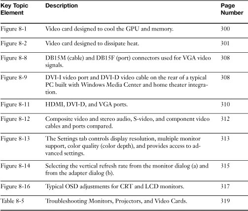
Review the most important topics in the chapter, noted with the key topics icon in the outer margin of the page. Table 8-6 lists a reference of these key topics and the page numbers on which each is found.
Table 8-6 Key Topics for Chapter 8
Complete the Tables and Lists from Memory
Print a copy of Appendix B, “Memory Tables,” (found on the CD), or at least the section for this chapter, and complete the tables and lists from memory. Appendix C, “Memory Tables Answer Key,” also on the CD, includes completed tables and lists to check your work.
Definitions of Key Terms
Define the following key terms from this chapter, and check your answers in the glossary.
CRT,
VGA,
SVGA,
DVI,
HDMI,
RGB,
Troubleshooting Scenario
Your client is experiencing problems with the display on his monitor. He informs you that the screen is blurry and will not provide a display over 800 by 600. What would you tell the client to try?
Refer to Appendix A, “Answers to the ‘Do I Know This Already?’ Quizzes and Troubleshooting Scenarios,” for the answer.