
Chapter 7. I/O and Multimedia Ports and Devices
This chapter covers a portion of the CompTIA A+ 220-701 objectives 1.1, 1.2, 1.8, and 1.9, and CompTIA A+ 220-702 objectives 1.1 and 1.2
Input/output (I/O) devices allow us to control the computer and display information in a variety of ways. There are a plethora of ports that connect these devices to the computer, for example, the well-known USB port. To fully understand how to install, configure, and troubleshoot input, output, and multimedia devices, you need to know the ports like the back of your hand. In this chapter you will learn about serial, parallel, SCSI, USB, sound, and FireWire ports; the goal is to make you proficient with the various interfaces you will see in the IT field.
“Do I Know This Already?” Quiz
The “Do I Know This Already?” quiz allows you to assess whether you should read this entire chapter or simply jump to the “Exam Preparation Tasks” section for review. If you are in doubt, read the entire chapter. Table 7-1 outlines the major headings in this chapter and the corresponding “Do I Know This Already?” quiz questions. You can find the answers in Appendix A, “Answers to the ‘Do I Know This Already?’ Quizzes and Troubleshooting Scenarios.”
Table 7-1 “Do I Know This Already?” Foundation Topics Section-to-Question Mapping
1. Which of the following can be used with the SCSI- (Small Computer Systems Interface) based technology? (Choose two.)
a. High-performance and high-capacity hard drives
b. Image scanners
c. Hubs
d. Switches
2. When daisy-chaining SCSI devices, what must each device have? (Choose two.)
a. Each device must have a unique SCSI device ID.
b. They must have a separate bus.
c. Each end of the daisy-chain must be terminated.
d. They require their own adapter.
3. A serial port can hook up devices such as external modems and label printers. What is this port usually called?
a. SCSI port
b. COM port
c. PS/2 ports
d. Parallel port
4. Which of the following devices can be used for a printer port, scanner, or removable media?
a. PS/2 port
b. Parallel port
c. NIC card
d. I/O port
5. Which device is known as IEEE 1394?
a. USB
b. Parallel port
c. FireWire
d. PS/2
6. Some desktop systems and many of the older laptop and portable systems include a port to connect a mouse or keyboard. What is this port called?
a. USB
b. FireWire
c. BIOS
d. PS/2
7. What is the standard size of the audio mini-jack used by sound cards?
a. 1 1/2 inch
b. 1/8 inch
c. 2 1/2 inch
d. 1 inch
8. There are two standards for USB ports. What are they? (Choose two.)
a. USB 1.1
b. USB 3.2
c. USB 1.0
d. USB 2.0
9. If you run out of USB ports and need more, which of the following devices are available? (Choose all that apply.)
a. Motherboard connectors
b. USB hubs
c. Add-on cards
d. Extra PCI slots
10. Which device still remains the primary method used to enter data and send commands to the computer?
a. Mouse
b. Gamepad
c. Stylus
d. Keyboard
11. Which of the following is used to transfer data into a computer by pressing on screen icons?
a. Touch screen monitors
b. CRT monitors
c. LCD monitors
d. Serial ports
12. Which of the following are considered multimedia devices? (Choose all that apply.)
a. Webcam
b. Sound card
c. Microphone
d. All of these options are correct
13. You have just attached speakers to a sound card that you know to be working. After you restart the computer you notice that no sound is coming out. Which of the following could be the problem? (Choose two.)
a. The sound card was not seated properly.
b. The sound card is defective.
c. The speakers are turned off.
d. The speakers are plugged into the wrong jack.
14. You are in the process of installing a new keyboard to a new PC. Which of the following is the most common type of connector to use?
a. Blu-ray connector
b. PS/2 connector
c. USB connector
d. PS/3 connector
15. Which of the following can cause problems with keyboards? (Choose all that apply.)
a. A damaged keyboard connector on the computer
b. A damaged keyboard cable
c. Dirt, dust, or gunk in the keyboard
d. None of these apply
16. Which of the following would you check first when troubleshooting multiple USB devices that are not recognized by Windows?
a. Disable the device in Windows
b. Reinstall the driver
c. Enable USB ports in the BIOS
d. Flash the BIOS
17. You have been informed by a user that his mouse is not working correctly. After asking some questions you have discovered that he is using a ball and roller design. Which of the following steps can you take to correct the problem? (Choose all that apply.)
a. Open the access cover to release the ball
b. Shake loose any dust
c. Turn the rollers until you see the grime or dirt
d. Wipe the rollers clean
Foundation Topics
Understanding I/O Ports
I/O ports are used to send information to and from the processor and memory. While the most important I/O port on recent systems is the USB port, you might also encounter other ports, including legacy ports such as serial and parallel. The following sections explain the major features of each port type covered by the A+ Certification exams.
USB
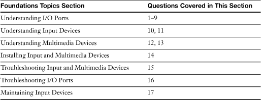
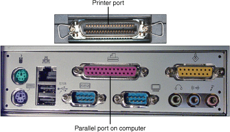
Universal Serial Bus (USB) ports have largely replaced PS/2 (mini-DIN) mouse and keyboard, serial (COM), and parallel (LPT) ports on recent systems. Most recent desktop systems have at least four USB ports, and many systems support as many as eight or more front- and rear-mounted USB ports. Figure 7-1 shows the rear panel of a typical ATX system, including USB and other port types discussed in this chapter.
Figure 7-1 A typical ATX motherboard’s I/O ports, complete with legacy (serial, parallel, PS/2 mouse and keyboard), four USB, one IEEE 1394, two Ethernet, and audio ports.
![]()
The following sections describe USB port types and how to add more USB ports.
USB Port Types, Speeds, and Technical Details
There are two standards types of USB ports you need to know for the exam:
• USB 1.1
• USB 2.0 (also called Hi-Speed USB)
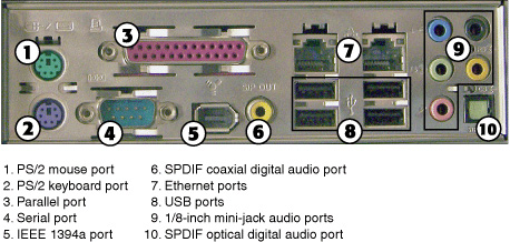
Both standards use the same cable and connector types, which are shown in Figure 7-2.
Figure 7-2 USB plugs and sockets.
![]()
USB cables use two different types of connectors: Series A (also called Type A) and Series B (also called Type B). Series A connectors are used on USB root hubs (the USB ports in the computer) and USB external hubs to support USB devices. Series B connectors are used for devices that employ a removable USB cable, such as a USB printer or a generic (external) hub. Generally, you need a Series A–to–Series B cable to attach most devices to a USB root or external hub. Cables that are Series A–to–Series A or Series B–to–Series B are used to extend standard cables, and can cause problems if the combined length of the cables exceeds recommended distances. Adapters are available to convert Series B cables into Mini-B cables, which support the Mini-B port design used on many recent USB devices.
Tip
I don’t recommend using extension cables or cables that are longer than 6 feet (especially with USB 1.1 ports or with any type of hub-powered device); I’ve seen some devices stop working when longer-than-normal cables were used. If you need a longer cable run, use a self-powered hub between the PC and the device. The self-powered hub provides the power needed for any USB device and keeps the signal at full strength.
USB 1.1 ports run at a top speed (full-speed USB) of 12 megabits per second (Mbps), low-speed USB devices such as a mouse or a keyboard run at 1.5Mbps, and USB 2.0 (Hi-Speed USB) ports run at a top speed of 480Mbps. USB 2.0 ports are backward-compatible with USB 1.1 devices and speeds, and manage multiple USB 1.1 devices better than a USB 1.1 port does.
USB packaging and device markings frequently use the official logos shown in Figure 7-3 to distinguish the two versions of USB in common use. Note that the industry is shifting from using the term “USB 2.0” to “Hi-Speed USB.”
Figure 7-3 The USB logo (left) is used for USB 1.1–compatible devices, whereas the Hi-Speed USB logo (right) is used for USB 2.0–compatible devices. Devices bearing these logos have been certified by the USB Implementers Forum, Inc.

With either version of USB, a single USB port on an add-on card or motherboard is designed to handle up to 127 devices through the use of multiport hubs and daisy-chaining hubs. Starting with Windows 98, USB devices are Plug and Play (PnP) devices that are hot swappable (can be connected and disconnected without turning off the system). The USB ports (each group of two ports is connected to a root hub) in the computer use a single IRQ and a single I/O port address, regardless of the number of physical USB ports or devices attached to those ports.
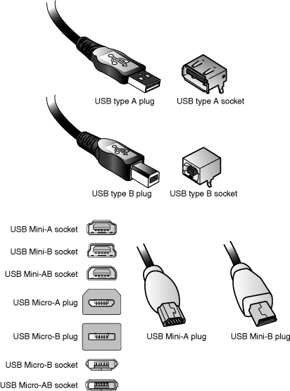
The maximum length for a cable attached to 12Mbps or 480Mbps USB devices is 5 meters, whereas the maximum length for low-speed (1.5Mbps) devices such as mice and keyboards is 3 meters. When a USB root hub is enabled in a computer running Windows, two devices will be visible in the Windows Device Manager: a USB root hub and a PCI-to-USB universal host controller (USB 1.1) or advanced host controller (USB 2.0), which uses the single IRQ and I/O port address required by USB hardware. If an external USB hub is attached to the computer, a generic hub also will be listed in the Windows Device Manager (see Figure 7-4). A root hub supports two USB ports. In Figure 7-4, there are two root hubs listed, indicating that the system has four USB ports.
Figure 7-4 The USB section of the Windows XP Device Manager on a typical system. Note the fork-shaped USB logo next to the category and each device.
![]()
Adding USB Ports
Need more USB ports? You can add USB ports with any of the following methods:
• Motherboard connectors for USB header cables
• Hubs
• Add-on cards
Some motherboards have USB header cable connectors, which enable you to make additional USB ports available on the rear or front of the computer. Some motherboard vendors include these header cables with the motherboard, whereas others require you to purchase them separately. Some recent case designs also include front-mounted USB ports, which can also be connected to the motherboard. Because of vendor-specific differences in how motherboards implement header cables, the header cable might use separate connectors for each signal instead of the more common single connector for all signals.
USB generic hubs enable you to connect multiple devices to the same USB port and to increase the distance between the device and the USB port. There are two types of generic hubs:
• Bus-powered
• Self-powered
Bus-powered hubs might be built into other devices, such as monitors and keyboards, or can be standalone devices. A bus-powered hub distributes both USB signals and power via the USB bus to other devices. Different USB devices use different amounts of power, and some devices require more power than others do. A bus-powered hub provides no more than 100 milliamps (mA) of power to each device connected to it. Thus, some devices fail when connected to a bus-powered hub.
A self-powered hub, on the other hand, has its own power source; it plugs into an AC wall outlet. It can provide up to 500mA of power to each device connected to it. A self-powered hub supports a wider range of USB devices, and I recommend using it instead of a bus-powered hub whenever possible.
SCSI
SCSI (Small Computer Systems Interface) is a very flexible interface because it can accommodate many devices in addition to hard disk drives. Currently, SCSI interfaces, either on the motherboard or as add-on cards, are found primarily in servers and are used for mass storage (hard disk, tape backup), although you might encounter workstations and PCs that use SCSI interfaces for devices such as
• High-performance and high-capacity hard drives
• Image scanners
• Removable-media drives such as Zip, Jaz, and Castlewood Orb
• High-performance laser printers
• Optical drives
• Tape backups
So-called Narrow SCSI host adapters (which use an 8-bit data channel) can accommodate up to seven devices of different varieties on a single connector. Wide SCSI host adapters use a 16-bit data channel and accommodate up to 15 devices on a single connector.
Multiple Device Support with SCSI Host Adapters
All true SCSI host adapters are designed to support multiple devices, although some low-cost SCSI host adapters made especially for scanners and Zip drives might not support multiple devices (also known as daisy-chaining). Several SCSI features permit daisy-chaining:
• External SCSI peripherals have two SCSI ports, enabling daisy-chaining of multiple devices.
• Internal SCSI ribbon cables resemble IDE data cables, only wider.
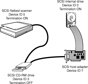
• Both internal and external SCSI peripherals enable the user to choose a unique device ID number for each device to distinguish one peripheral from another in the daisy-chain (see Figure 7-5).
Figure 7-5 When a SCSI host adapter card with internal and external connectors is used, the SCSI daisy-chain can extend through the card. Note that the devices on each end of the chain are terminated, and each device (including the host adapter) has a unique device ID number.
![]()
Multiple device support enables the different types of devices listed previously to work on a single SCSI host adapter. To determine which device IDs are in use, you can
• Physically examine each SCSI device’s device ID settings.
• Scan the SCSI bus with a software program such as Adaptec’s SCSI Interrogator or with the BIOS routines built into some SCSI host adapters.
• View the properties for each SCSI device in the Windows Device Manager.
Jumper Block and DIP Switch Settings for Device IDs
Each SCSI device must have a unique device ID to distinguish itself from other SCSI devices connected to the same SCSI channel. Narrow SCSI (50-pin data cable) devices use a set of three jumpers or DIP switches to set the device ID. Wide SCSI (68-pin data cable) devices use a set of four jumpers or DIP switches to set the device ID.
The device ID is set in binary (base 2) values in order from bit 0 (least significant bit or LSB) to the most significant bit or MSB. Table 7-2 lists the settings for narrow SCSI devices (IDs 0–7); Table 7-3 lists the settings for wide SCSI devices (IDs 0–15).
Table 7-2 Narrow SCSI LSB-to-MSB Device ID Settings
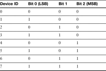
Table 7-3 Wide SCSI LSB-to-MSB Device ID Settings
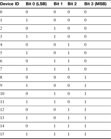
In the following tables, 1 means jumper block on or DIP switch set to ON; 0 means jumper block off or DIP switch set to OFF.
Device ID 7 is usually reserved for use by the SCSI host adapter. I’ve highlighted it in the following tables as a reminder to avoid using ID 7 for another device.
Tables 7-2 and 7-3 assume that the jumper blocks or DIP switches place bit 0 at the left. If the device places bit 0 at the right, reverse the order in the preceding list when setting the configuration.
Tip
The jumper blocks or DIP switches used to configure the device ID might be part of a larger array of jumper blocks or DIP switches used to set all drive features. Check the documentation for the drive to determine which jumper blocks or DIP switches to use.
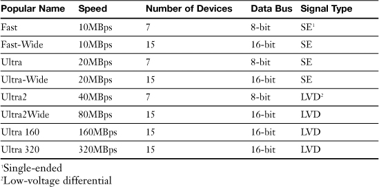
SCSI Standards
SCSI actually is the family name for a wide range of standards, which differ from each other in the speed of devices, number of devices, and other technical details. The major SCSI standards are listed in Table 7-4.
Table 7-4 Popular SCSI Standards
![]()
8-bit versions of SCSI use a 50-pin cable or a 25-pin cable; wide (16-bit) versions use a 68-pin cable.
SCSI host adapters are generally backward compatible, enabling older and newer SCSI standards to be mixed on the same host adapter. However, mixing slower and faster devices can cause the faster devices to slow down unless you use a host adapter with dual buses that can run at different speeds.
SCSI Cables
Just as no single SCSI standard exists, no single SCSI cabling standard exists. In addition to the 50-pin versus 68-pin difference between standard and wide devices, differences also appear in the Narrow SCSI external cables. Figure 7-6 compares internal SCSI cables for wide and narrow applications, and Figure 7-7 compares various types of external SCSI cables and ports.
Figure 7-6 A wide (68-pin) SCSI ribbon cable (left) compared to a narrow (50-pin) SCSI ribbon cable (right).
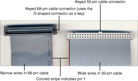
Figure 7-7 Wide (68-pin) and narrow (50-pin, 25-pin) SCSI cable connectors (left) and the corresponding SCSI port connectors (right).
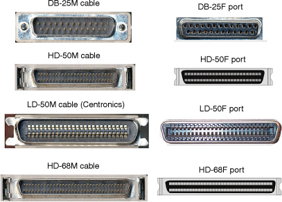
Compare Figure 7-6 to Figure 12-8 to see the resemblance between SCSI 50-pin ribbon cables and PATA (ATA/IDE) cables: SCSI 50-pin cables resemble PATA cables but are wider. However, three different types of Narrow SCSI external connectors are available (see Figure 7-7):
• 50-pin Centronics— Similar to, but wider than, the 36-pin Centronics port used for parallel printers. Also called LD50.
• 50-pin high-density connector (HD50)— The Wide SCSI 68-pin connector (HD68) uses the same design, but with 34 pins per row instead of 25 pins per row.
• 25-pin DB-25F— Physically, but not electronically, similar to the DB-25F parallel printer port.
Most recent external 8-bit (narrow) SCSI devices use the HD50 connector, whereas older models use the LD50 (Centronics) connector. However, a few low-cost SCSI devices such as the Iomega Zip-100 drive and some SCSI scanners use only the 25-pin connector, which lacks much of the grounding found on the 50-pin cable. Some SCSI devices provide two different types of SCSI connectors. Consequently, you need to determine what cable connectors are used by any external SCSI devices you wish to connect together.
SCSI Signaling Types
In Table 7-3 (previously shown), SE stands for single-ended, a SCSI signaling type that runs at speeds of up to 20MBps only. SE signaling enables relatively inexpensive SCSI devices and host adapters to be developed, but it reduces the length of cables and the top speed possible.
Ultra2, Ultra2Wide, Ultra 160, and Ultra 320 devices all use a signaling standard called low-voltage differential (LVD), which enables longer cable runs and faster, more reliable operation than the single-ended (SE) standard allows. Some LVD devices can also be used on the same bus with SE devices, but these multimode, or LVD/SE devices, will be forced to slow down to the SE maximum of 20MBps when mixed with SE devices on the same bus. Some advanced SCSI host adapters feature both an SE and an LVD bus to enable the same adapter to control both types of devices at the correct speeds.
Daisy-Chaining SCSI Devices
When you create a SCSI daisy-chain, you must keep all these factors in mind:
• Each device must have a unique SCSI device ID (refer to Table 7-2 and Table 7-3).
• Each end of the daisy-chain must be terminated. Some devices have an integral switch or jumper block for termination (see Figures 7-8 and 7-9), whereas some external devices require that you attach a terminator (which resembles the end of a SCSI cable) to the unused SCSI connector.
Figure 7-8 A SCSI-based internal CD-R drive with (left to right) well-marked jumpers for termination and device ID, power connector, data cable pin 1, and CD-audio cable.
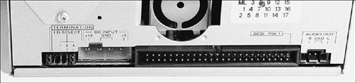
Figure 7-9 External termination and device ID selector switches on a SCSI-based scanner. This scanner has both DB25-F and Centronics-50 (also called LD50-F) SCSI ports.
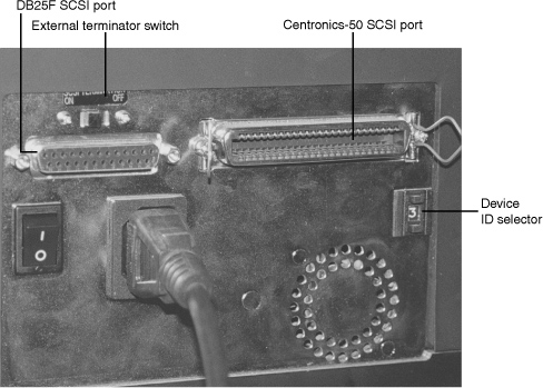
• When daisy-chaining external devices, double-check the cable connector type and purchase appropriate cables. You will often need SCSI cables that have different connectors at each end because of the different connector types used (see Figure 7-9).
SCSI Host Adapter Card Installation
Follow these steps to install a PnP SCSI host adapter card:
Step 1. Check the card’s documentation and make any required adjustments in the PnP configuration in the BIOS before installing the card. You might need to change the type of IRQ setting used or reserve a particular IRQ for the card.
Step 2. Install the card into the appropriate ISA or PCI expansion slot.
Step 3. Turn on the system.
Step 4. When the card is detected by the system, you’ll be prompted for installation software. Insert the appropriate disk or CD-ROM and follow the prompt to complete the installation.
Step 5. Reboot the system and use the Windows Device Manager to view the card’s configuration.
SCSI Daisy-Chain Maximum Length
The maximum length of a SCSI daisy-chain depends upon the speed of the devices used and the type of signaling in use.
Single-ended (SE) signaling requires a shorter bus length as transmission speed increases. See Table 7-5 for details.
Table 7-5 Single-Ended SCSI Maximum Bus Length
The now-obsolete high-voltage differential (HVD) SCSI signaling standard supports a maximum bus length of 25 meters with any number of devices.
Low-voltage differential (LVD) SCSI signaling (supported on Ultra2 SCSI and faster versions) supports cabling length of 12 meters with any number of devices.
Caution
If you mix single-ended and LVD devices on the same SCSI bus, you limit the length of the bus as shown in Table 7-5. Use separate host adapters or a multichannel adapter to avoid this problem.
Figure 7-10 shows you the standard markings used to identify SE, LVD, and LVD-SE SCSI devices. LVD-SE devices can be used with either SE or LVD devices on the same daisy-chain.
Figure 7-10 SE, LVD, and LVD-SE SCSI device markings.

SCSI Termination Methods
Both ends of a SCSI daisy-chain need to be terminated for proper operation. Although SCSI host adapters are designed to provide automatic termination, you must terminate other types of devices manually.
Low-speed external SCSI devices such as scanners and Zip drives often feature internal termination, which is configured with a switch on the unit. Some internal SCSI devices use a jumper block or DIP switch to configure termination; others use a terminating resistor pack.
Terminators are connected to the unused port on an external SCSI device or inline with the ribbon cable on an internal SCSI device if built-in termination is not available or is not used. There are two types of external termination:
• Passive
• Active
Passive terminators use no power. Passive terminators are not recommended if more than two SE devices are on a SCSI daisy-chain and are not recommended with LVD or LVD-SE devices.
Active terminators use an external power source to provide a voltage regulator for better termination. They can be used with LVD, LVD-SE, and SE-based SCSI daisy-chains.
Tip
Make sure you know the connector type, speed, and termination type appropriate for your SCSI device before you order a terminator. Ask the vendor for help if you aren’t sure what you need. There are many varieties to choose from.
Serial (COM)
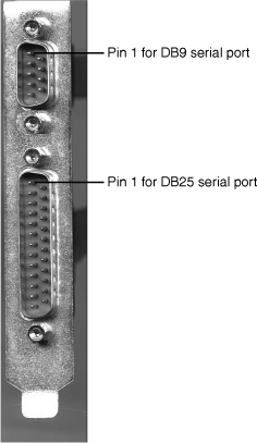
The serial port, also known as RS-232 or COM (communication) ports, historically has rivaled the parallel port in versatility (see Figure 7-11). Serial ports have been used to connect the following:
Figure 7-11 A 9-pin serial port (DB-9M connector, top) and a 25-pin serial port (DB-25M connector, bottom) on a typical extension bracket from a multi-I/O card. The ribbon cables used to connect the ports to the card can be seen in the background.
![]()
• External modems
• Serial mouse or pointing devices such as trackballs or touchpads
• Plotters
• Label printers
• Serial printers
• Digital cameras
• PC-to-PC connections used by file transfer programs such as Direct Cable Connection, LapLink, and Interlink
Note
The DB-9 is actually a DE-9 connector, but is colloquially known as “DB-9” and will most likely be referred to as such on the exam. The smaller the D-sub connector, the higher the letter.
How do serial ports compare in speed with parallel ports? Serial ports transmit data one bit at a time (parallel ports send and receive data eight bits at a time), and their maximum speeds are far lower than parallel ports. However, serial cables can carry data reliably at far greater distances than parallel cables. Serial ports, unlike parallel ports, have no provision for daisy-chaining; only one device can be connected to a serial port. Because USB ports provide greater speed than both serial and parallel ports and support multiple devices connected to a single port via hubs, it’s no wonder that a lot of devices that formerly plugged into the serial port are now calling the USB port “home port.”
Serial ports come in two forms:
• DB-9M (male)
• DB-25M (male)
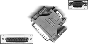
Either type can be adapted to the other connector type with a low-cost adapter (see Figure 7-12). The difference is possible because serial communications need only a few wires. Unlike parallel printers, which use a standard cable, each type of serial device uses a specially wired cable. DB-9M connectors are used on all but the oldest systems.
Figure 7-12 A typical DB-25F to DB-9M serial port converter. The DB-25F connector (lower left) connects to the 25-pin serial port and converts its signals for use by devices attaching to the DB-9M port at the other end (upper right).
Serial Port Pinouts
At a minimum, a serial cable must use at least three wires, plus ground:
• A transmit data wire
• A receive data wire
• A signal wire
Tables 7-6 and 7-7 can be used to determine the correct pinout for any specified serial cable configuration. Unlike parallel devices, which all use the same standard cable wiring, serial devices use differently wired cables. A modem cable, for example, will be wired much differently than a serial printer cable. And different serial printers might each use a unique pinout.
Table 7-6 9-Pin Serial Port Pinout
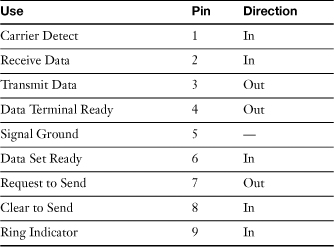
Table 7-7 25-Pin Serial Port Pinout
Note
The DB-9 (9-pin male) connector is the more common of the two serial port connector types. The 25-pin serial port has many additional pins but is seldom used today. The major difference between it and the 9-pin serial interface is the 25-pin port’s support for current loop data, a type of serial communications primarily used for data collection in industrial uses.
Table 7-7 lists the pinouts for the 25-pin connector; unused pins are omitted.
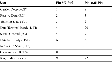
When a 9-pin to 25-pin serial port adapter is used (see Figure 7-12), the pins are converted to the more common 25-pin connector (see Table 7-8).
Table 7-8 9-Pin to 25-Pin Serial Port Converter/Serial Modem Pinout
Serial ports assume that one end of the connection transmits and the other end receives.
Types of Serial Cables
Serial cables, unlike parallel cables, can be constructed in many different ways. In fact, cables for serial devices are usually specified by device type rather than port type. This is because different devices use different pinouts.
Some of the most common examples of serial cables include
• Null-modem (data transfer) cable
• Modem cable
A null-modem cable enables two computers to communicate directly with each other by crossing the receive and transmit wires (meaning that two computers can send and receive data, much like a computer network, though much slower). The best known of these programs is LapLink, but the Windows Direct Cable Connection/Direct Serial Connection utilities can also use this type of cable. Although these programs support serial cable transfers, parallel port transfers are much faster and USB transfers are much faster than parallel; these methods for direct connection are recommended for most versions of Windows. However, Windows NT 4.0 and earlier do not support using the parallel port for file transfers, so you must use a null-modem cable such as the one shown in Figure 7-13.
Figure 7-13 A LapLink serial cable with connectors for either 25-pin or 9-pin serial ports. Only three wires are needed, enabling the cable to be much thinner than the 9-pin serial extension cable also shown.

A modem cable is used to connect an external modem to a serial port. Some modems include a built-in cable, but others require you to use a DB-9F to DB-25M cable from the 9-pin connector on the serial port to the 25-pin port on the modem. This cable typically uses the same pinout shown in Table 7-8.
What about serial printers? These printers are used primarily with older terminals rather than with PCs, and because different printers use different pinouts, their cables must be custom-made. In fact, I’ve built a few myself. Fortunately, most recent terminals use parallel or USB printers.
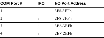
Standard IRQ and I/O Port Addresses
Serial ports require two hardware resources: IRQ and I/O port address. Table 7-9 lists the standard IRQ and I/O port addresses used for COM ports 1–4. Some systems and add-on cards enable alternative IRQs to be used, either through jumper blocks (older cards) or via software/Device Manager configuration (newer cards).
Table 7-9 Standard Settings for COM (Serial) Ports 1–4
![]()
Note that serial ports never require a DMA channel (and thus can’t have DMA conflicts with other devices). However, there’s another way to stumble when working with serial ports: IRQ conflicts. IRQ 4 is shared by default between COM 1 and COM 3; IRQ 3 is shared by default between COM 2 and COM 4. However, with serial ports that use the same IRQ, sharing does not mean that both serial ports can be used at the same time. If a device on COM 1 and a device on COM 3 that share the same IRQ are used at the same time, both devices will stop working and they might shut down the system.
How to Configure or Disable Serial Ports
Depending on the location of the serial port, there are several ways to configure the port settings to select different IRQ and I/O port addresses for a serial port, or to disable the serial port. These include
• BIOS setup program for built-in ports
• PnP mode for use with Windows
To adjust the configuration of a serial port built into the system’s motherboard, follow these steps:
Step 1. Start the BIOS setup program.
Step 2. Go to the peripherals configuration screen.
Step 3. Select the serial port you want to adjust.
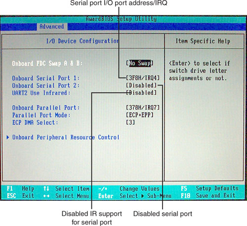
Step 4. To change the port’s configuration, choose the IRQ and I/O port address you want to use, or select Disabled to prevent the system from detecting and using the serial port (see Figure 7-14).
Figure 7-14 A typical BIOS I/O device configuration screen with the first serial port enabled, the second port disabled, and IR (infrared) support disabled.
Step 5. Save changes and exit; the system reboots.
Serial ports on PCI or PCI Express cards are configured by the PnP BIOS. In some cases, you can use the Windows Device Manager to change the port configuration (see Chapter 15, “Troubleshooting and Mainaining Windows,” for details).
Serial Port Software Configuration
Unlike parallel ports, serial ports have many different configuration options, making successful setup more challenging. Through software settings at the computer end, and by hardware or software settings at the device end, serial devices can use
• A wide variety of transmission speeds, from as low as 300 bps to as high as 115,200 bps or faster
• Different word lengths (7 bit or 8 bit)
• Different methods of flow control (XON/XOFF or DTR/DSR)
• Different methods of ensuring reliable data transmission (even parity, odd parity, no parity, 1-bit or 2-bit parity length)
Although simple devices such as a mouse or a label printer don’t require that these settings be made manually (the software drivers do it), serial printers used with PCs running terminal-emulation software, PCs communicating with mainframe computers, serial pen plotters, serial printers, and PCs using modems often do require that these options be set correctly. Both ends of a serial connection must have these configurations set to identical values, or the communications between your computer and the other device will fail.
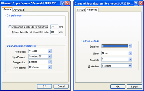
Figure 7-15 illustrates how Windows XP configures the port speed, flow control, and hardware settings for a serial port connected to an external modem.
Figure 7-15 General (left) and Advanced (right) dialog boxes used in Windows XP to configure a serial port connected to an external modem.
![]()
Adding Additional Serial Ports
You can add additional serial ports to a system with any of the following:
• PCI-based serial or multi-I/O card
• PCI Express-based serial or multi-I/O card
• USB-to-serial-port adapter
Parallel (LPT)
The parallel port, also known as the LPT (Line Printer) port, was originally designed for use with parallel printers. However, don’t let the name “LPT port” fool you. Historically, the parallel port has been among the most versatile of I/O ports in the system because it was also used by a variety of devices, including tape backups, external CD-ROM and optical drives, scanners, and removable-media drives such as Zip drives. Although newer devices in these categories are now designed to use USB or IEEE 1394 ports, the parallel port continues to be an important external I/O device for older systems.
Caution
Devices other than printers that plug into the parallel (LPT) port have two connectors: one for the cable that runs from the device to the parallel port, and another for the cable that runs from the device to the printer. Although it’s theoretically possible to create a long daisy-chain of devices ending with a printer, in practice you should have no more than one device plus a printer plugged into a parallel port. If you use more than one device, you could have problems getting the devices (not to mention the printer) to work reliably.
The parallel (LPT) port is unusual because it uses two completely different connector types:
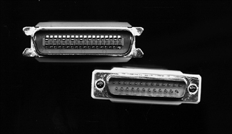
• Since the first IBM PC of 1981, all IBM and compatible computers with parallel ports have used the DB-25F port shown in Figure 7-16, with pins 1–13 on the top and pins 14–25 on the bottom. This is also referred to as the type IEEE-1284-A connector. (IEEE 1284 is an international standard for parallel port connectors, cabling, and signaling.)
Figure 7-16 Parallel devices use the Centronics port (top) for printers and some other types of parallel devices, whereas the DB-25F port (bottom) is used for the computer’s parallel port. Some external devices also use a DB-25F port.
![]()
• The port used by parallel printers of all types, however, is the same Centronics 36-pin port used since the days of the Apple II and other early microcomputers of the late 1970s, as seen in Figure 7-16. This port is also referred to as the IEEE-1284-B port. It is an edge connector with 36 connectors, 18 per side.
Some Hewlett-Packard LaserJet printers also use a miniature version of the Centronics connector known as the IEEE-1284-C, which is also a 36-pin edge connector. The 1284-C connector doesn’t use wire clips.
Accordingly, a parallel printer cable also has different connectors at each end, as seen in Figure 7-17.
Figure 7-17 The ends of a typical IBM-style parallel cable. The Centronics 36-pin connector (upper left) connects to the printer; the DB-25M connector (lower right) connects to the computer’s DB-25F parallel port.
Parallel cables have the pinout described in Table 7-10.
Table 7-10 Parallel Port Pinout (DB-25F Connector)

Note
Note that the parallel designation for the LPT port comes from its use of eight data lines (pins 2–9) and that the port has provisions for printer status messages (pins 10–12).
Parallel Port Configuration
The configuration of the LPT port consists of the following:
• Selecting the port’s operating mode
• Selecting the IRQ, I/O port address, and DMA channel (for certain modes)
The LPT port can be configured for a variety of operating modes. The options available for a particular port depend on the capabilities of the system. Most systems you’re likely to work with should offer all of these modes, although a few digital dinosaurs still kicking around in some offices might not have the IEEE-1284 modes.
These modes differ in several ways, including port performance, whether the port is configured for output only or for bidirectional (input-output) operation, and the types of hardware resources such as IRQ, DMA, and I/O port addresses used.
Standard Mode The standard mode of the LPT port is the configuration first used on PCs, and it is the only mode available on very old systems. On some systems, this is also known as compatible mode. Although configuration for this mode typically includes both the IRQ and I/O port address, only the I/O port address is actually used for printing. If the parallel port is used in standard/compatible mode, IRQ 7 can be used for another device. The standard mode is the slowest mode (150 kilobytes per second [KBps] output/50KBps input), but it is the most suitable mode for very old printers. In this mode, eight lines are used for output, but only four lines are used for input. The port can send or receive, but only in one direction at a time.
This mode will work with any parallel cable.
PS/2—Bidirectional The next mode available on most systems is the PS/2 or bidirectional mode. This mode was pioneered by the old IBM PS/2 computers and is the simplest mode available on some computer models.
Bidirectional mode is more suitable for use with devices other than printers because eight lines are used for both input and output, and it uses only I/O port addresses. This mode is no faster than compatible mode for printing but accepts incoming data at a faster rate than compatible mode; the port sends and transmits data at 150KBps.
This mode requires a bidirectional printer cable or IEEE-1284 printer cable.
IEEE-1284 High-Speed Bidirectional Modes Three modes that are fully bidirectional (able to send and receive data 8 bits at a time) and are also much faster than the original PS/2-style bidirectional port include
• EPP (Enhanced Parallel Port)— Uses both an IRQ and an I/O port address. This is the mode supported by most high-speed printers and drives attached to the parallel port.
• ECP (Enhanced Capabilities Port)— Designed for daisy-chaining different devices (such as printers and scanners) to a single port. It uses an IRQ, an I/O port address, and a DMA channel, making it the most resource hungry of all the different parallel port modes.
• EPP/ECP— Many recent systems support a combined EPP/ECP mode, making it possible to run devices preferring either mode on a single port.
These modes, which transmit data at up to 2 megabytes per second (MBps) and receive data at 500KBps, have all been incorporated into the IEEE-1284 parallel port standard. Most Pentium-based and newer systems have ports that comply with at least one of these standards. All of these require an IEEE-1284–compliant parallel cable.
These modes are suitable for use with
• High-speed laser and inkjet printers
• External tape-backup drives, optical drives, and Zip drives
• Scanners
• Data-transfer programs such as Direct Cable Connection, Direct Parallel Connection, LapLink, Interlink, and others
Basically, the list includes all of the most recent printers and peripherals that plug into the parallel port.
Types of Parallel Cables There are three major types of parallel cables:
• Printer— Uses the DB-25M connector on one end, and the Centronics connector on the other.
• Switchbox/Device— Most use the DB-25M connector on both ends.
• Data transfer— Uses the DB-25M connector at both ends and crosses the transmit and receive wires at one end (meaning that two computers can send and receive data, much like a computer network, though much slower).
Caution
If you use a switchbox or device cable in place of a data transfer cable, or vice-versa, your device or your data transfer process won’t work. Fortunately, data transfer cables are usually thinner than switchbox or device cables because only a few of the wire pairs are required for data transfer. However, you might want to label the different types of cables to avoid mixing them up.
Printer and switchbox/device cables can support the IEEE-1284 or earlier bidirectional standards. Here’s how they differ internally:
• IEEE-1284 cables feature several types of shielding in both the cable and at the printer end of the cable. This shielding is designed to minimize interference from outside sources. Normal cables have minimal shielding.
• IEEE-1284 cables use a twisted wire-pair construction internally, running 18 wire pairs to the printer. The wire pairs help minimize crosstalk (interference between different wires in the cable). Standard (compatible) cables don’t use as many wire pairs, and bidirectional cables use less shielding. As a result, IEEE-1284 cables are both a good deal thicker and more expensive than ordinary or bidirectional printer cables.
Tip
When purchasing or selecting parallel cables, IEEE-1284–compatible cables can be used with any parallel port mode and provide superior signal quality. New cables are clearly marked as IEEE-1284 compliant on the package. Existing cables often have IEEE-1284 marked on the rubberized outer shield of the cable.
Standard and Optional Parallel Port Settings Parallel ports can be configured as LPT1, LPT2, and LPT3. When a single parallel port is found in the system, regardless of its configuration, it is always designated as LPT1. The configurations for LPT2 and LPT3, shown in Table 7-11, apply when you have a computer with more than one parallel port.
Table 7-11 Typical Parallel Port Hardware Configuration Settings

![]()
If one of the ports is an ECP or EPP/ECP port, DMA 3 is normally used on most systems along with the IRQ and I/O port address ranges listed here. Some computers default to DMA 1 for an ECP or EPP/ECP parallel port, but DMA 1 will conflict with most sound cards running in Sound Blaster emulation mode.
PCI or PCI Express-based multi-I/O cards can place the parallel port at any available IRQ. PCI parallel port or multi-I/O (parallel and serial ports and possibly others on the same card) cards can share IRQs with other PCI cards. However, ISA parallel ports, including those built into the motherboard, cannot share IRQs when used in EPP, ECP, or EPP/ECP mode (these modes use an IRQ).
How to Configure or Disable Parallel Ports Depending on the location of the parallel port, there are a couple of ways to configure the port settings in recent systems. These include
• BIOS setup program for built-in ports
• PnP mode for use with Windows
Follow these steps to adjust the configuration of a parallel port built into the system’s motherboard:
Step 1. Start the BIOS setup program.
Step 2. Change to the I/O device or peripheral configuration screen (see Figure 7-18).
Figure 7-18 A typical BIOS I/O device configuration screen with the parallel port configured for EPP/ECP mode with default settings.

Step 3. Select the mode, IRQ, I/O port address, and DMA channel if required.
Step 4. Save changes and exit; the system reboots.
PCI-based parallel ports are configured by the PnP BIOS. In some cases, you can adjust the settings used by a PnP parallel port or a motherboard-based parallel port with Windows Device Manager. See Chapter 15 for details.
Adding Parallel Ports Although you can daisy-chain a printer and another parallel-port device to a single parallel port, you can’t connect two printers to the same port unless you use a switchbox. If you want to have two parallel printers that can be used at the same time, or if you want to provide different parallel-port devices with their own ports, you need to add a parallel port. What are your options?
You can add additional parallel ports to a system with any of the following:
• PCI-based parallel or multi-I/O card
• PCI Express-based parallel or multi-I/O card
• USB-to-parallel-port adapter
Tip
A USB-to-parallel-port adapter has a USB Type A connection at one end and a Centronics connection at the other end. This adapter enables you to connect a parallel printer to your USB port so you can use the parallel port for other devices. However, this type of adapter isn’t designed to support other types of parallel port devices. If you want to connect a parallel port drive or scanner, you must use a real parallel port.
IEEE 1394 (FireWire)
IEEE 1394 is a family of high-speed bidirectional serial transmission ports that can connect PCs to each other, digital devices to PCs, or digital devices to each other.
The most common version of IEEE 1394 is known as IEEE 1394a, and is also known as FireWire 400. Sony’s version is known as i.LINK. At 400Mbps, IEEE 1394a is one of the fastest and most flexible ports used on personal computers. IEEE 1394a can be implemented either as a built-in port on the motherboard (refer to Figure 7-1) or as part of an add-on card (see Figure 7-19).
Figure 7-19 A typical IEEE 1394a host adapter card with three external and one internal ports.

![]()
IEEE 1394 Ports and Cables
Standard IEEE 1394a ports and cables use a 6-pin interface (four pins for data, two for power), but some digital camcorders and all i.LINK ports use the alternative 4-pin interface, which supplies data and signals but no power to the device. Six-wire to four-wire cables enable these devices to communicate with each other.
A faster version of the IEEE 1394 standard, IEEE 1394b (also known as FireWire 800), runs at 800Mbps. IEEE 1394b ports use a 9-pin interface. There are two versions of the IEEE 1394b port: The Beta port and cable are used only for 1394b-to-1394b connections, whereas the Bilingual cable and port are used for 1394b-to-1394a or 1394b-to-1394b connections. Beta cables and ports have a wide notch at the top of the cable and port, whereas Bilingual cables and ports have a narrow notch at the 1394b end, and use either the 4-pin or 6-pin 1394a connection at the other end of the cable. All four cable types are shown in Figure 7-20.
Figure 7-20 1394b and 1394a cable connectors compared.

IEEE 1394–Compatible Devices and Technical Requirements
IEEE 1394–compatible devices include internal and external hard drives, digital camcorders (also referred to as DV camcorders), web cameras, MP3 players (such as older models of Apple’s iPod) and high-performance scanners and printers, as well as hubs, repeaters, and SCSI to IEEE 1394 converters. IEEE 1394 ports support hot-swapping, enabling you to add or remove a device from an IEEE 1394 port without shutting down the system. 1394 ports can also be used for networking with Windows XP (but not Vista).
Up to 16 IEEE 1394 devices can be connected to a single IEEE 1394 port through daisy-chaining. Most external IEEE 1394 devices have two ports to enable daisy-chaining.
Windows 98 was the first version of Windows to include IEEE 1394 support. IEEE 1394 cards can use PCI or PCI Express buses (versions for laptops use ExpressCard or CardBus designs) and require the following hardware resources:
• One IRQ (it can be shared on systems that support IRQ sharing by PCI devices)
• One memory address range (must be unique)
The exact IRQ and memory address range used by a particular IEEE 1394 card can be determined by using the Windows Device Manager. When an IEEE 1394 card is installed, a device category called 1394 Bus Controller is added to the Device Manager, and the particular card installed is listed beneath that category.
Installing an IEEE 1394 Card
To install and configure an IEEE 1394 card, follow this procedure:
Step 1. Turn off the computer and remove the case cover.
Step 2. Locate an available PCI or PCI Express expansion slot.
Step 3. Remove the slot cover and insert the card into the slot. Secure the card in the slot.
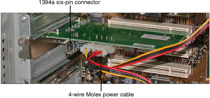
Step 4. Some IEEE 1394 cards are powered by the expansion slot, whereas others require a 4-pin connector for power. Connect a power lead if the card requires it; you can use a Y-splitter to free up a power lead if necessary (see Figure 7-21).
Figure 7-21 A typical IEEE 1394a card after installation. This card requires a four-wire power cable and also includes an internal port.
Step 5. Close the system, restart it, and provide the driver disk or CD-ROM when requested by the system.
Step 6. The IRQ and memory address required by the card will be assigned automatically.
PS/2 (Mini-DIN)
PS/2 ports (also referred to as Mini-DIN ports) are used by PS/2 keyboards, mice, and pointing devices. Most desktop systems, and many older laptop and portable systems, include PS/2 ports.
In a typical ATX/BTX port cluster, the bottom PS/2 port is used for keyboards, and the top PS/2 port is used for mice and pointing devices. On systems and devices that use the standard PC99 color coding for ports, PS/2 keyboard ports (and cables) are purple, and PS/2 mouse ports (and cables) are green. Refer to Figure 7-1 for the location of these ports.
Centronics
Centronics ports are used by parallel (LPT) printers and by some older narrow SCSI devices. Centronics parallel ports use a 36-pin edge connector (refer to Figure 7-17), while Centronics SCSI ports use a 50-pin edge connector (refer to Figure 7-7).
For more information about parallel (LPT) ports, see the section “Parallel (LPT),” earlier in this chapter. For more information about SCSI ports, see the section “SCSI,” earlier in this chapter.
1/8-inch Audio Mini-Jack
The 1/8-inch audio mini-jack is used by sound cards and motherboard-integrated sound for speakers, microphone, and line-in jacks, as shown in Figure 7-1.
To avoid confusion, most recent systems and sound cards use the PC99 color coding listed as follows:
• Pink— Microphone in
• Light Blue— Line in
• Lime Green— Stereo/headphone out
• Brown— Left to right speaker
• Orange— Subwoofer
SPDIF Digital Audio
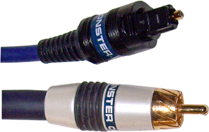
Many systems include both analog audio (delivered through 1/8-inch audio minijacks) and digital audio. Sony/Philips Digital Interconnect Format (SPDIF) ports output digital audio signals to amplifiers, such as those used in home theater systems, and come in two forms: optical and coaxial.
Optical SPDIF uses a fiber optic cable, while coaxial SPDIF uses a shielded cable with an RCA connector. The cables are shown in Figure 7-22. To see SPDIF ports, refer to Figure 7-1.
Figure 7-22 SPDIF optical (top) and coaxial (bottom) cables.
Sound cards might incorporate SPDIF ports into the card itself or into drive bay or external extension modules.
Tip
By default, systems with both analog and digital output use analog output. To enable digital output, use the Sounds and Audio Devices dialog in Windows Control Panel or the proprietary mixer provided with some sound cards or onboard audio devices.
MIDI Port
Some sound cards feature MIDI ports. MIDI ports are used to communicate with MIDI keyboards. Older devices with MIDI support use MIDI ports that use a five-pin DIN design similar to the original IBM PC keyboard jack, while newer devices use the smaller Mini-DIN design, but with five pins instead of the six pins used by PS/2 keyboards and mice.
Figure 7-23 illustrates a drive bay-mounted module that contains MIDI ports. Note that some older sound cards use adapters that connect to the joystick port.
Figure 7-23 MIDI ports in a Creative Labs add-on module for sound cards.

RG-6 Coaxial
RG-6 coaxial connections are used by TV and FM radio tuners to receive signals from broadcast and cable TV and radio. Figure 7-24 illustrates a typical TV tuner card with an F-connector and an RG-6 cable.
Figure 7-24 TV tuner cards use RG-6 cables for video sources such as broadcast and cable TV.
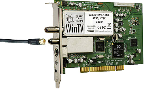
To enjoy TV broadcasts on your PC, you must also use software that can tune in the appropriate station, display the video, and play back the audio. To enjoy FM radio broadcasts on your PC, you must also use software that can tune in the appropriate station and play back the audio. Most recent TV and radio tuner cards and devices are bundled with suitable software and drivers for Windows Media Center.
Understanding Input Devices
Modern PCs use many different types of input devices, including keyboards and mice, bar code readers, biometric devices, and touch screens. The following sections cover the important characteristics of each of these devices.
Keyboard
The keyboard remains the primary method used to send commands to the computer and enter data. You can even use it to maneuver around the Windows Desktop if your mouse or other pointing device stops working.
Keyboards can be connected through dedicated keyboard connectors or through the USB port. Extremely old systems use the 5-pin DIN connector, whereas newer systems use the smaller 6-pin mini-DIN connector (also called the PS/2 keyboard connector) shown in Figure 7-1.
Some recent systems use the USB port for the keyboard, and any system with USB ports can be equipped with a USB keyboard if the system BIOS supports USB Legacy mode and if the system runs an operating system that supports USB ports (Windows 98 or newer).
Most recent systems use the 104-key keyboard layout, which includes Windows keys on each side of the space bar and a right-click key next to the right Ctrl key. Otherwise, the 104-key keyboard’s layout is the same as the older 101-key keyboard.
Mouse and Pointing Devices
Next to the keyboard, the mouse is the most important device used to send commands to the computer. For Windows users who don’t perform data entry, the mouse is even more important than the keyboard. Mouse alternatives, such as trackballs or touchpads, are considered mouse devices because they install and are configured the same way.
Current mice and pointing devices use the USB 1.1 or USB 2.0 port, but older models used the 6-pin PS/2 (mini-DIN), serial (COM) ports, or 8–pin bus mouse port.
Some mice sold at retail work with either the USB port or the PS/2 port and include a PS/2 adapter. This adapter and others are shown in Figure 7-25.
Figure 7-25 A USB keyboard–to–PS/2 keyboard port adapter (top) compared to a USB mouse–to–PS/2 mouse port adapter (middle) and serial mouse–to–PS/2 mouse port adapter (bottom).
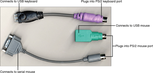
Note
Adapters cannot be used successfully unless the mouse (or keyboard) is designed to use an adapter. A mouse designed to use an adapter is sometimes called a hybrid mouse.
Mouse Resource Usage
A USB mouse uses the IRQ and I/O port address of the USB port to which it is connected. Because a single USB port can support up to 127 devices through the use of hubs, a USB mouse doesn’t tie up hardware resources the way other mouse types do.
A PS/2 mouse uses IRQ 12; if IRQ 12 is not available, the device using that IRQ must be moved to another IRQ to enable IRQ 12 to be used by the mouse. A serial mouse uses the IRQ and I/O port address of the serial port to which it is connected.
Bar Code Reader
Bar code readers are used in a variety of point-of-sale retail, library, industrial, medical, and other environments to track inventory.
Bar code readers use one of the following technologies:
• Pen-based readers use a pen-shaped device that includes a light source and photo diode in the tip. The point of the pen is dragged across the bar code to read the varying thicknesses and positions of the bars in the bar code and translate them into a digitized code that is transmitted to the POS or inventory system.
• Laser scanners are commonly used in grocery and mass-market stores. They use a horizontal-mounted or vertical-mounted prism or mirror and laser beam protected by a transparent glass cover to read bar codes.
• CCD or CMOS readers use a hand-held gun-shaped device to hold an array of light sensors mounted in a row. The reader emits light that is reflected off the bar code and is detected by the light sensors.
• Camera-based readers contain many rows of CCD sensors that generate an image of the sensor that is processed to decode the barcode information.
Biometric Devices
A biometric device is used to prevent access to a computer or other electronic device by anyone other than the authorized user. It does so by comparing the fingerprint or other biometric marker of the prospective user to the information stored by the authorized user during initial setup. Some keyboards and laptop computers include built-in fingerprint readers, and some vendors also produce USB-based fingerprint readers.
To learn more about fingerprint readers and other biometric devices, see Chapter 10, “Security.”
Touch Screens
Touch screen (or touchscreen) monitors enable the user to transfer data into the computer by pressing onscreen icons. Touch screen monitors are very popular in public-access and point-of-sale installations.
Touch screen monitors use CRT or LCD technology and also incorporate one of the following surface treatments to make the monitor touch sensitive:
• Four-wire resistive technology— Uses a glass panel coated with multiple layers that conduct and resist electricity. A flexible polyester cover sheet fits over the glass panel and is separated from the panel with insulating separator dots. The outer side of the cover has a durable coating; the inner side has a conductive coating. When the cover is pressed, an electrical signal is generated and is sent through the interface to the computer. The lowest-cost touchscreen technology, this type of screen is designed for public use.
• Five-wire resistive technology— A more sensitive and more accurate version of four-wire resistive technology suitable for use by trained personnel (offices, point-of-sale, and so on).
• Surface wave— Uses horizontal and vertical piezoelectric transducers to create ultrasonic waves. Touching the screen overlay disrupts the waves and the coordinates of the touch determine what signal is sent to the computer. It’s a durable surface able to compensate for surface damage and dirt and is suitable for self-service applications such as banking or information kiosks.
• Touch-on-tube— Combines surface wave technology with direct touch contact to the CRT; no overlay is necessary. LCDs use an overlay with a simple air gap between the overlay and the panel surface. Suitable for self-service applications.
• Scanning infrared— A light grid created by infrared (IR) signals is used to sense touches. Works with plasma as well as other types of displays.
Touch screens are available in freestanding versions similar to normal desktop CRT and LCD displays as well as in kiosk and built-in designs.
Touch Screen Interfacing to the Computer
Touch screens, like ordinary LCD and CRT monitors, use standard VGA analog or DVI digital interfaces to the video card. However, the touch signals are transmitted to the computer through a separate interface known as the touch screen controller. Touch screen controllers can use either of the following interfaces:
• Serial (RS-232)— Some touch screen monitors have an internal serial controller; others use an external serial controller. The internal serial controller might use a standard 9-pin serial cable or a special PS/2–to–9-pin serial cable to connect the controller to a serial (COM) port on the computer, depending upon the monitor model. The external serial controller uses a controller with a built-in serial cable.
• USB— A touch screen monitor with an internal USB interface uses a standard USB cable to connect to a USB port on the computer.
Understanding Multimedia Devices
Multimedia devices such as webcams, digital cameras, MIDI ports, microphones, sound cards, and video capture cards are used by both home and business-oriented PCs. The following sections discuss the characteristics of each of these devices.
Webcam
A webcam is a simple digital camera capable of taking video or still images for transmission over the Internet. Unlike digital cameras (next section), webcams don’t include storage capabilities.
Most webcams plug into a USB port, but a few have used IEEE 1394 or parallel ports.
Webcams are generally used in live chat situations, such as with AOL Instant Messenger or other IM clients. They offer resolutions ranging from sub-VGA to as high as 2 million pixels (2 megapixels). Some offer autofocus and zoom features for better image clarity, and some have built-in microphones.
Digital Camera
Digital cameras have largely replaced film cameras for both amateur and professional photography. They use CMOS or CCD image sensors to record images onto internal or card-based flash memory form factors such as Compact Flash, SD, Memory Stick, xD-Picture Card, and Smart Media.
Digital cameras transfer images to computers for emailing, printing, or storage via either flash memory card readers or direct USB port connections.
MIDI Music and MIDI Ports
Musical instrument digital interface (MIDI) music is created from digitized samples of musical instruments that are stored in the ROM or RAM of a MIDI device (such as a sound card) and played under the command of a MIDI sequencer. MIDI sequences can be stored as files for future playback, and can be transferred between sound cards and MIDI-enabled devices such as keyboards via the MIDI port. To learn more about MIDI ports, see the section “MIDI Port,” earlier in this chapter.
Sound Card
Sound cards are used to record and play back analog audio, and most can also play back digital audio sources as well. When recording analog audio sources such as CDs, line in or microphone in, sound cards digitize the audio at varying sample rates and store files in either uncompressed forms such as WAV or compressed forms such as WMA or MP3.
Most recent sound cards support 5.1 or 7.1 surround audio, and many sound cards also support digital stereo or surround audio playback standards via SPDIF ports. In recent years, sound cards have become less popular due to the popularity of onboard audio, but sound cards are preferred by users who create audio recordings.
Figure 7-26 illustrates a typical soundcard.
Figure 7-26 Typical input and output jacks on a typical sound card (the Creative Labs X-Fi Xtreme Gamer).
Microphone
Microphones plug into the 1/8-inch mini-jack microphone jack on a sound card or integrated motherboard audio. The most common microphones used on PCs include those built into headsets (Figure 7-27) or those which use a stand.
Figure 7-27 A typical PC stereo headset with microphone.

Microphone volume is controlled by the Windows Sounds and Audio Devices applet’s mixer control. Open the Recording tab to adjust volume, to mute or unmute the microphone, or to adjust microphone boost.
Note
The microphone jack is monaural, whereas the line-in jack supports stereo. Be sure to use the line-in jack to record from a stereo audio source.
Video Capture Card
As the name suggests, video capture cards are used to capture live video from various sources, including analog camcorders, VCRs, analog output from DV camcorders, broadcast TV, and cable TV. Most recent cards with video capture capabilities are actually multi-purpose cards that include other functions. These include ATI’s All-in-Wonder series of video (graphics) cards with onboard TV tuner and video capture functions, video (graphics) cards with VIVO (video-in/video-out) S-video or composite video ports, and TV tuner cards and USB devices. Video can be stored in a variety of formats, including MPEG, AVI, and others for use in video productions.
Installing Input and Multimedia Devices
The installation processes for the most common input and multimedia devices are covered in the following sections.
Installing a Keyboard
To install the keyboard using a DIN or mini-DIN jack, turn off the power and insert the connector end of the keyboard cable into the keyboard connector (usually on the back of the computer). No special drivers are required unless the keyboard has special keys, a programmable feature, or is a wireless model that uses a receiver. Note that systems with a PS/2 keyboard port usually also have a PS/2 mouse port. Be sure to use the PS/2 keyboard port; check the color code or the keyboard icon next to the port to verify you are using the correct port. To remove the keyboard, turn off the power before removing the connector end of the keyboard cable from the keyboard connector.
To install a USB keyboard, enable USB Legacy mode in the system BIOS (see Chapter 4, “BIOS,” for details); then plug the keyboard into a USB port built into the computer, or into a USB hub plugged into a USB port built into the computer. With Windows 98 Second Edition and newer versions of Windows, the keyboard can be plugged and unplugged as desired without shutting down the system. Note that some USB keyboards include an adapter that enables them to connect to PS/2 keyboard ports (refer to Figure 7-25). USB keyboards are part of the HID (human interface device) device category, and Windows installs HID drivers after the keyboard is connected.
Installing a Mouse or Other Pointing Device
The physical installation of a serial or PS/2 mouse or other point devices such as a touchpad is extremely simple. Turn off the computer and plug the mouse into the appropriate connector. Then, restart the computer. That’s it!
To install a USB mouse or other pointing device (such as a touchpad), plug it into any USB port on a system running Windows 98 or newer versions. Install any software drivers required.
Unlike keyboards, mouse devices require software drivers. Windows includes support for standard mice from Microsoft and other vendors. However, if you are installing a mouse that includes zooming, tilt-wheel, or additional buttons, you might need to install the drivers provided with the mouse or updated versions provided by the vendor to assure full support for additional features.
Installing a Bar Code Reader
Wired bar code readers typically interface through the USB port, PS/2 keyboard port, or the serial (COM, RS-232) port. Bar code readers that plug into the PS/2 keyboard port use a device known as a keyboard wedge to enable a keyboard and bar code reader to be plugged into the keyboard port at the same time. Serial interface bar code readers use a software program to convert serial data into keystrokes or to perform dynamic data exchange (DDE) to applications. USB-based bar code readers emulate either the PS/2 or Serial interface, depending upon the software used to interface the reader.
See the documentation for the reader to determine if you install the driver before or after connecting the reader. If the reader plugs into a PS/2 keyboard or serial port, you must shut down the computer before connecting the reader. If the reader plugs into a USB port, you can connect the reader while the system is running.
Note
Some bar code readers use Bluetooth to make a wireless connection between the reader and the computer or other data-acquisition device.
Installing a Webcam
Webcams connect to the PC’s USB port, and can thus be connected while the computer is running. However, before connecting the webcam, check the documentation to determine if you need to install drivers and application software before or after connecting the webcam.
Most webcams work with modern instant messaging (IM) software to provide live video chat capabilities, but some might also include proprietary software. Check the documentation to determine compatible software.
Installing a Digital Camera
To connect a digital camera to your PC, follow these steps:
Step 1. Connect the USB cable provided with the camera to the camera’s USB port and the computer’s USB port.
Step 2. Turn on the camera.
Step 3. If the camera is not recognized after a few seconds, select the picture playback option on the camera. If the camera is still not recognized, install drivers for the camera.
Some digital cameras are assigned a drive letter, while others show up as an imaging device in My Computer. If the camera is assigned a drive letter, you can drag and drop photos from the camera to other storage locations just as you would with any other disk drive. If the camera is detected as an imaging device, you should install the software drivers and utilities included with your camera to provide the necessary support for transferring and converting photos.
Installing a MIDI Port
Many sound cards include MIDI interfacing as part of the card’s standard features. However, it is usually necessary to connect MIDI ports to the card. If the card’s MIDI ports are not connected, follow this procedure:
Step 1. Shut down the computer and disconnect it from AC power.
Step 2. Connect the MIDI ports to the sound card. If the game port is also used for MIDI interfacing and the game port is already connected to the sound card, connect the MIDI adapter cable to the game port. However, if the game port is not connected, or if the MIDI ports are built into a separate adapter, connect the game port or adapter to the sound card.
Step 3. Restore AC power and restart the system.
Step 4. Provide drivers as prompted.
Installing a Microphone
To install a microphone on a PC with a sound card or integrated audio, follow this procedure:
Step 1. Plug the microphone into the microphone jack, which is marked with a pink ring or a microphone icon.
Step 2. Systems that support AC’97 version 2.3 audio might pop up a dialog that asks you to confirm the device you have plugged into the microphone jack. Select Microphone from the list of devices.
To verify that the microphone is working:
Step 1. Open the Sounds and Audio Devices icon in Control Panel.
Step 2. Click Test Hardware.
Step 3. Click Next.
Step 4. If prompted by Windows Firewall, unblock the test program (you might see more than one prompt).
Step 5. Speak into the microphone when prompted to test your microphone and then click Next.
Step 6. Speak into the microphone when prompted to test your speakers and then click Next.
Step 7. Click Finish.
If you do not hear any output from the microphone, open the Audio tab, click the Volume button in the Sound Recording section of the dialog, and make sure the Mic volume control is not muted. Adjust the volume level as desired.
Installing a Biometric Device
The most common biometric device used with PCs is a fingerprint reader. Fingerprint readers plug into a computer’s USB port, and the driver software should be installed before the reader is connected:
Step 1. Install the software provided with the reader. This might include a driver program and a password-management program.
Step 2. After the programs are installed, connect the reader to a USB port built into the PC.
Step 3. Run the configuration program to set up the reader to recognize the user. This will require the user to press or wipe his or her finger against the reader and save the results for comparison during later attempts to start the system or access secure websites.
Installing a Touch Screen
To install a touch screen monitor, follow these steps:
Step 1. Shut down the computer and disconnect it from AC power.
Step 2. Connect the monitor to the appropriate VGA or DVI port on your computer.
Step 3. Connect the serial or USB cable to the touch screen and to the appropriate port on the computer.
Step 4. Restart the computer.
Step 5. Install the serial or USB driver for the touch screen interface.
Installing a Sound Card
To install a sound card, follow these steps:
Step 1. Shut down the computer and disconnect it from AC power.
Step 2. Open the case to gain access to the PC’s expansion slots.
Step 3. Determine the type of slot needed for the sound card. Some use PCI slots, while others use PCI Express x1 slots.
Step 4. Locate an empty PCI or PCI Express expansion slot as needed.
Step 5. Remove the corresponding bracket from the back of the case.
Step 6. Slide the card into the slot.
Step 7. Fasten the card bracket into place, using the screw or locking mechanism you removed or released in Step 5.
Step 8. Close the system.
Step 9. Restore AC power and restart the system.
Step 10. Install the drivers provided with the sound card, or updated versions provided by the vendor.
Step 11. Connect speakers, microphone, line-in and line-out cables as needed to support your audio or home theater subsystem.
Step 12. Open the Sound and Audio Devices icon in Control Panel and configure volume and speaker settings to match your configuration.
Installing a Video Capture Card
The process of installing a video capture card includes the following steps.
Step 1. Shut down the computer and disconnect it from AC power.
Step 2. Open the case to gain access to the PC’s expansion slots.
Step 3. Determine the type of slot needed for the sound card. Some use PCI slots, while others use PCI Express x1 slots.
Step 4. Locate an empty PCI or PCI Express expansion slot as needed.
Step 5. Remove the corresponding bracket from the back of the case.
Step 6. Slide the card into the slot.
Step 7. Fasten the card bracket into place, using the screw or locking mechanism you removed or released in Step 5.
Step 8. Close the system.
Step 9. Restore AC power and restart the system.
Step 10. Install the drivers provided with the video capture card, or updated versions provided by the vendor.
Step 11. Connect the cables needed for video sources, such as composite or S-video (to capture video from VCRs, TV-out ports, or analog camcorders) or RG-6 coaxial (to capture video from TV sources such as antennas or cable TV).
Step 12. Set up the video capture software to work with the video source(s) you are using.
Troubleshooting Input and Multimedia Devices
The following sections tell you how to troubleshoot the most common input and multimedia devices. For more information about using Windows Device Manager, see the section “Device Manager,” in Chapter 13.
Troubleshooting Keyboards
Keyboard problems usually result from a few simple causes:
• A damaged keyboard connector on the computer
• A damaged keyboard cable
• Dirt, dust, or gunk in the keyboard
To learn how to clean a keyboard, see the section “Maintaining Keyboards,” later in this chapter.
The following are some ways to avoid these problems:
• Don’t plug a PS/2 keyboard into a system that’s powered up. This is an excellent way to destroy the motherboard!
• Don’t plug a PS/2 keyboard into a system at an angle. This tends to break the solder joints that attach the keyboard connector to the motherboard.
To determine whether a keyboard has failed, plug it into another system. A defective keyboard will not work in any system. However, if every keyboard plugged into a keyboard port fails to work, the keyboard port is defective. Use a USB keyboard or replace the motherboard.
If the normal keys on the keyboard work but multimedia or other special keys do not work, reinstall the drivers made for that keyboard.
Troubleshooting Mice and Pointing Devices
Although Windows supports keyboard shortcuts for some operations, a mouse is required for maximum utility. Use this section to prepare for troubleshooting questions on the A+ Certification Exam and day-to-day mouse problems.
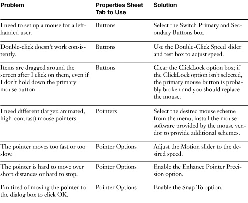
Table 7-12 shows you how to use the Mouse Properties sheet for Windows XP to solve common pointing device problems. Other versions of Windows offer similar features, although some advanced options might not be present. All Properties sheet tabs are shown in Figure 7-28.
Table 7-12 Using the Pointing Device Properties Sheet

![]()
Figure 7-28 The Mouse Properties sheet for a wheel mouse used on a system running Windows XP.
Mouse Pointer Won’t Move
If the mouse pointer won’t move when the mouse is moved, check the following:
• Check the mouse software driver— Use the Mouse icon in the Control Panel to verify that the correct mouse driver has been selected under Windows. Using the wrong mouse driver can cause the mouse pointer to freeze.
• Check the mouse connection to the system— If a PS/2 mouse isn’t plugged in tightly, the system must be shut down, the mouse reconnected to the PS/2 mouse port, and the system restarted to enable the mouse to work. USB mouse devices can be hot-swapped at any time with Windows 98 Second Edition and newer versions. If a serial mouse is used on the system and it is not detected during Windows startup, Windows normally will display a message instructing you to plug in the mouse.
• Check for hardware conflicts— Serial and PS/2 mouse devices must have exclusive access to the IRQ used by the port to which the mouse is connected. If you use another device that uses the same IRQ, the mouse pointer will freeze onscreen and the system can lock up. Use the Windows Device Manager to verify that there are no IRQ conflicts between the port used by the mouse and other devices. If necessary, use the PnP configuration in the system BIOS setup to select IRQ 12 (used for PS/2 mouse devices) as excluded or as an ISA IRQ.
• Make sure the port used by the mouse is enabled in the system BIOS— If the PS/2 mouse port is disabled, a PS/2 mouse won’t work. If the USB ports are disabled, a USB mouse won’t work. Recent systems with four or more USB ports sometimes provide an option for enabling only some of the USB ports. Check the system BIOS and make any changes needed. (See Chapter 4 for details.)
• Make sure the mouse can work with a port adapter— Many mouse devices sold at retail can be used with either a serial port or PS/2 port, or with either a USB port or PS/2 mouse port. The mouse has one port type built in and uses an adapter supplied with the mouse to attach to the other port type with which it is compatible. These mouse devices also contain special circuitry to enable them to work with either port type. Don’t mix up the adapters used by different brands and models of mouse devices; mismatches might not work. Mouse devices bundled with systems typically don’t have the extra circuitry needed to work with an adapter; they’re built to attach to one port type only. Mouse devices that can work with adapters are sometimes referred to as hybrid mouse devices.
Jerky Mouse Pointer Movement
The most common causes of jerky mouse pointer movement include
• Dirt or dust on the mouse or trackball rollers which are used to transmit movement signals to the computer—Applies to mechanical mice.
• Low battery power—Applies to wireless mice.
• Unsuitable mousing surface—Applies to wired and wireless mice with optical sensors.
• Interference from other wireless devices—Applies to wireless mice.
• Obstructions between mouse and receiver—Applies to wireless mice.
Mice with optical (non-laser) sensors cannot use surfaces with no detail (such as a mirror) or repetitive detail. Mice with laser sensors can use these surfaces.
If a wireless mouse uses a manual frequency control, try alternative frequencies to avoid interference. If a wireless mouse relies upon IR signaling, make sure there are no obstacles between the IR transmitter in the mouse and the IR receiver plugged into the PC. For details on how to clean a mouse or other pointing device, see the section “Maintaining Mice and Pointing Devices,” later in this chapter.
The speed of the mouse pointer can also be adjusted with the Mouse icon in the Windows Control Panel. Select the Movement tab and adjust the Cursor Speed and Acceleration tab to make the mouse pointer move faster or slower across the screen.
User Can’t Double-Click Icons
Damaged mouse buttons can prevent a user from double-clicking on icons in Windows. Turn off the system if necessary, substitute an identical mouse, and restart the system to see if the mouse is the problem. If changing mouse devices doesn’t solve the problem, use the Mouse icon in the Windows Control Panel to adjust the double-click speed to the user’s preference.
Troubleshooting Touch Screen
Touch Screens can malfunction for several reasons, including
• Display problems common to any monitor (loss of signal, incorrect colors, and so on).
• Software problems such as corrupted or incorrectly configured drivers or applications.
• Video alignment problems (you touch the screen but the wrong menu item or action takes place or the cursor moves in the opposite direction of your finger or stylus).
• Hardware problems caused by the touchscreen itself, the controller, cabling, or power.
To troubleshoot hardware or software problems, use the diagnostic programs supplied with the touchscreen to verify that the hardware is working. If the hardware is working correctly, the driver software used to interface the operating system and the touchscreen must be checked. See the documentation for the touchscreen monitor for details.
To solve problems caused by misalignment, realign the video using the utilities provided with the touchscreen.
To troubleshoot hardware problems, use the diagnostic features provided with the touchscreen controller to determine if it is working correctly. The controller might use LEDs or onscreen messages to indicate problems. Next, use utilities provided by the touchscreen vendor to determine if the controller is transmitting touch data.
If constant touch data is being sent by the controller when you aren’t touching the screen, the controller might be defective, the monitor bezel might be touching the screen, or the touchscreen or cable has a short. If no touch data is being sent by the controller when you touch the screen, check the controller, cable, power supply, or controller setup.
Troubleshooting Sound Card
Sound cards can be difficult to troubleshoot because of their complex hardware requirements, software driver requirements, need to use add-on speakers for output, and potential for conflicts. Use this section to prepare for sound card troubleshooting questions that might appear on the A+ Certification exams or in your day-to-day work.
Sound Card Plays Sounds But Can’t Record CD-Quality Sound
Older sound cards that emulate the ISA Sound Blaster use two different DMA channels, typically DMA 1 for 8-bit sounds and DMA 5 for 16-bit sounds. If your sound card plays Windows startup and event sounds but you can’t record sounds in CD quality (44KHz, stereo), check for conflicts between the sound card’s DMA channels and another device that uses DMA. Verify that a 16-bit DMA (5, 6, or 7) is being used by the card’s configuration by checking the sound card’s configuration with the Windows Device Manager. Move any conflicting device to a different DMA channel.
Sound Card Works in Some Systems But Not in Others
Motherboards with onboard audio will conflict with add-on sound cards unless the motherboard-based sound is disabled before the sound card is installed.
Sound Playback Is Distorted or Choppy
Out-of-date drivers are the most common cause for distorted or choppy sound. Download and install the latest drivers for the sound card. Use a different expansion slot to help avoid resource sharing with other devices.
No Sound at All from Sound Card
A sound card that doesn’t play sound might not be defective; instead, the cause could be volume controls or speaker problems. Check the following:
• On-card volume controls— Some very old sound cards use an external rotary volume control; make sure this is set to at least the midway point.
• Windows mixer controls— When a sound card is installed on a Windows system, a volume control for playback and recording features is normally installed in the system tray. Double-click the speaker icon to view the volume controls. If the play control is muted or set to minimum volume, you will not hear anything from the sound card. If individual features are muted or set to minimum volume, the sound card will play some types of sounds but not others.
• Incorrect jack used for speakers— As seen in Figure 7-1, the 1/8 inch minijacks used for speaker, microphone, and line-in are identical in shape. They are not always color coded with the PC99 standard discussed in the section “1/8-inch Audio Mini-Jack” earlier in this chapter. If the speakers are plugged into the wrong jack, you will hear nothing from the sound card. Verify you are using the correct jack for the speakers.
• No power to speakers— Most speakers used for computers can be powered by an AC adapter (some speakers also use batteries). Many low-cost speakers can play sounds at a low volume without power, but the speakers’ built-in amplification is turned off if the speaker is turned on but no power is present. Leave the speaker power off if no external power is present, and use the Windows volume control to control the speaker volume.
• Windows Device Manager— If the sound card is not visible in the Windows Device Manager, install it with the Add/Remove Hardware icon in Control Panel. If one or more components are listed with the yellow ! symbol indicating a problem, view the component properties and make sure that the proper drivers are installed and that there are no conflicts with other devices. Install new drivers or correct conflicts as needed, and restart the system if prompted to restore proper sound card operation.
Sound Card Can’t Play MIDI Files
MIDI files are special types of sound files that store an instrumental music score that is played by the sound card using either FM-based simulation of different musical instruments or stored samples of different musical instruments. If the sound card can’t play MIDI files, check the following:
• MIDI port (also called the MPU-401 port) might be disabled in the sound card configuration or have a conflict with another device— Use the Windows Device Manager to choose a configuration that enables the MIDI port or prevents a conflict with another device.
• MIDI samples might not be loaded into RAM or have been corrupted— MIDI instrumentation is built into some sound cards, but most use a so-called soft wavetable feature that stores the samples on the hard disk and loads them into RAM. Reload the samples from the original sound card driver disks or CD-ROM and verify that they are being loaded into RAM.
Tip
Many sound cards come with a diagnostic routine that will
• Play digitized sounds through each speaker (left and right) and both (stereo)
• Play MIDI tracks
Use the sound card’s diagnostics to check proper operation.
Troubleshooting SCSI Devices
SCSI problems can usually be traced to incorrect device ID, termination, or cabling.
External SCSI Device Isn’t Available
External SCSI devices might not be available for any of the following reasons:
• Device not powered on when the system was turned on
• Incorrect termination
• Excess cable length or excessive daisy-chain length
If an external SCSI device isn’t turned on a few seconds before the system is turned on, it might not initialize properly. If an external SCSI device is not turned on and the system has booted, it might be possible to use the Device Manager to activate the device by following this procedure:
Step 1. Turn on the device.
Step 2. Open Windows Device Manager.
Step 3. Click Refresh and wait for the system to recheck all connected devices.
Step 4. If the SCSI device now appears in Device Manager, you should be able to use it normally.
Step 5. If the device doesn’t appear, restart the system.
SCSI is a daisy-chained interface; both ends of the daisy-chain must be terminated. Make sure that the terminator switch or external terminator is located at the end of the external daisy-chain (the external terminator is plugged into the SCSI port not used by the SCSI cable attached to the device). If a new device has been added to the end of the daisy-chain, you must disable termination of the old device and add termination to the new device.
Faster SCSI standards support shorter maximum cable lengths than slower standards. Check the overall length of the daisy-chain if some external devices are unavailable and use the shortest cable lengths possible to avoid exceeding standards.
External or Internal SCSI Device Isn’t Available
If a new external or internal SCSI device is not available, two common reasons include
• Duplicate device ID numbers
• Failure to install drivers for device
If multiple SCSI devices have the same device ID number, the devices will interfere with each other. To solve this problem, power down all SCSI devices and the system and make sure each device has a unique device ID number before restarting.
Both the SCSI host adapter card and the SCSI devices attached to the card need operating system–compatible drivers to operate. With Windows 9x and newer Windows versions, SCSI devices are typically PnP, prompting you to install the driver the first time the device is found in the system. If the drivers are not loaded, use the Device Manager’s Properties sheet for each device to install a new driver.
If you need to install multiple SCSI devices, you should install one device and its device drivers before installing another device.
Troubleshooting I/O Ports
A multimedia or input device might appear to fail because of problems with the port the device is connected to. Use the following sections to diagnose port-specific problems.
Troubleshooting USB Ports and Devices
USB ports are the most common type of I/O port used on current systems. Use the following sections to solve problems with USB ports.
USB Devices Not Recognized
The following are several reasons why a USB device won’t be recognized when it is installed:
• USB port not enabled in system BIOS— USB ports can be disabled in the system BIOS. To re-enable USB ports, follow these steps:
Step 1. Restart the system.
Step 2. Start the BIOS setup program.
Step 3. Locate the correct menu for the USB ports (might be Advanced Chipset, Peripherals, or others, depending on the system).
Step 4. Enable USB function.
Step 5. Save the changes.
Step 6. Exit the system and reboot.
Step 7. Windows will install drivers for USB ports if they are not already installed.
• USB port not properly designed on older systems— Some of the early USB ports do not conform to current USB 1.1 or 2.0 standards and will not work with some or all USB peripherals, even using a supported version of Windows. Disable these ports and replace them with an add-on card containing USB ports.
• Drivers for device not properly installed— Windows 2000, Windows XP, and Windows Vista contain drivers for USB mass storage and input devices, but other types of USB devices, such as printers, scanners, digital cameras, and network adapters, require manufacturer-specific drivers that must be installed first. See the documentation for the device for details.
USB Port Problems
Problems with the USB port after operating system and driver issues have been resolved might be caused by the following issues:
• Not enough power for the device— If a device that uses more power than a bus-powered generic hub can provide is connected to a bus-powered generic hub, the device will fail. In some cases, you might see a warning displayed in the Windows system tray (see Figure 7-29). However, in all cases, the Power tab in the Generic USB Hub Properties sheet in Device Manager indicates the power usage per connected device and the per-port power available.
Figure 7-29 The Power tab in the Generic USB Hub Properties sheet in Windows XP indicates the Intel PC Camera Pro requires more power than the (bus-powered) hub can provide. In some cases, a pop-up warning appears to indicate this problem.
• USB controller displays yellow exclamation point (!) sign in Windows Device Manager— The USB PCI to USB controller (which runs the USB ports in the computer) might require a unique IRQ and I/O port address range on some older systems, unless IRQ sharing has been enabled in the system BIOS. Select nonconflicting IRQ and I/O port address ranges in the Properties sheet (Resources tab) for the USB controller, and restart the system if necessary.
• Too many full-speed (12Mbps) USB devices attached to a single USB 1.1 port— If the speed of existing devices drops after attaching a new device to the same USB hub, connect the new device to another USB port. If your system has USB 1.1 ports only, use a new hub connected to a separate USB port if needed to separate full-speed from low-speed USB devices. If your system has both USB 1.1 and USB 2.0 ports, attach a USB 2.0–compatible hub to a USB 2.0 port and attach all low-speed USB 1.1 devices to it.
• USB 2.0 devices do not operate at full (480Mbps) speed— Some systems can be configured to run USB ports in USB 1.1 or USB 2.0 modes. If USB ports are configured to run in USB 1.1 mode only, USB 2.0 devices will run very slowly, and a few might not work at all. Make sure USB ports are configured to run in USB 2.0 mode. Upgrade Windows XP to Service Pack 1 or greater to obtain USB 2.0 support. Upgrade Windows 2000 to Service Pack 4 to obtain USB 2.0 support.
Troubleshooting IEEE 1394 Ports and Devices
The following sections discuss the most common problems and solutions that apply to IEEE 1394 ports.
System Can’t Detect the IEEE 1394 Card or Port
So, you put the card in the system, turned it on, and Windows ignored it? If an IEEE 1394 card can’t be detected after it is physically installed in the system, check the following (be sure to turn off the system if you need to open it up again!):
• The card’s position in the slot— If the card is not properly seated in the expansion slot, reseat it.
• Power lead on cards that require an external power source— Some IEEE 1394 cards require additional power from a 4-pin power connector. If the power connector isn’t connected to the card, the card will not work when the system is turned on. Connect the power to the card and restart the system.
Caution
If you need to use a power splitter or extender to reach the card, make sure it’s connected to the power supply.
• IRQ conflict—Systems that use the advanced peripheral interrupt controller (APIC) can assign IRQs above 15 to PCI devices, and these devices can share IRQs. However, on older systems that do not support APIC, or have APIC disabled in the system BIOS, IRQ conflicts can take place. If the IEEE 1394 card listing in Windows Device Manager indicates a problem, use one of the following solutions: Restart the system and use the system BIOS setup program to select an unused IRQ for a particular PCI expansion slot; use the Windows Device Manager to reset either the IEEE 1394 card or the conflicting device to a different IRQ; move the card to a different slot.
• Port not enabled in system BIOS— If the 1394 ports built into the system don’t work, chances are they’re not enabled in the system BIOS. Restart the computer, enter the BIOS setup program, and enable them. Save the changes and exit.
Incorrect Driver for IEEE 1394 Card or Device
Several different chipsets are used on IEEE 1394 cards and devices. If drivers for the wrong chipset are installed, the card or device will not function. If an IEEE 1394 card or device displays the yellow ! sign in Windows Device Manager, check the properties for the card or device. If an IRQ or memory address conflict is not present, use the Driver tab to manually update to the correct driver. Download an updated driver from the vendor’s website.
Troubleshooting Parallel (LPT) Ports and Devices
If you are unable to use devices connected to parallel ports (such as printers), check the following:
• Parallel port mode not compatible with devices attached to the parallel port
• Incorrect order of devices when daisy-chaining multiple devices
• Cabling problems, including inadequate cabling for the parallel port mode selected, cabling too long for reliable printing, damage to port or cable, and incorrect cabling of parallel port header cable on multi-I/O cards
• Inadequate printer sharing device for mode selected
Parallel Port Mode Problems
If a parallel device designed to use an IEEE-1284 mode, such as EPP, ECP, or EPP/ECP, is attached to a parallel port that has the wrong mode selected or is set to slower modes, such as PS/2 bidirectional or standard/compatible, the device will work very slowly, or it might not work at all. Use the correct parallel port mode for the devices you need to attach to the port, and use an IEEE-1284–compatible cable to provide support for all parallel port modes.
Problems with Daisy-Chained Devices
Some systems daisy-chain devices such as Zip or other types of removable media drives or scanners to the same port as their printer. In many cases, the printer and any other single device can share the printer port. However, trying to use two or more devices along with the printer can cause slow performance or device failure.
To achieve success in using multiple parallel devices
Step 1. Check the device documentation for suggestions on which devices can be installed and in what order—in many cases, a printer and scanner or printer and removable-media drive will work, but other combinations might not work. Note that the printer is always at the end of the daisy-chain.
Step 2. Use the correct parallel port mode for the devices.
Step 3. Consider adding a second parallel port for some devices, switch to USB devices that can be connected to a USB hub, or connect the printer to a USB port with a USB-to-parallel-port adapter.
Cabling and Port Problems
Cables are always the weak point in any computer peripheral. Printers and other parallel devices are no exception. Parallel cables can cause several problems with printers and other devices. Low-quality cables that are longer than 10 feet can cause garbled printing, and cables that don’t support the port mode will prevent the port from reaching its maximum speed.
To avoid cabling problems, use a high-quality printer cable. Cables that meet the IEEE-1284 standard are recommended and will work well with any parallel port mode. IEEE-1284 cables provide the shielding necessary to ensure reliable printing beyond the 10-foot distance limitation of low-quality cables.
If you need to print at very long distances away from your computer, consider attaching the printer to a network or use a line converter (which changes parallel to serial signals).
Damaged cables will cause printing problems. If the printer will not print at all or prints garbage output, replace the cable with a known-working cable and retry the print job. Damaged ports will cause problems with any cable.
If a device connected to a parallel port that uses a header cable from a motherboard or add-on card doesn’t work, make sure the header cable is properly attached to the motherboard or add-on card. If the header cable is not connected properly, devices connected to the header cable will not work.
Testing Parallel Ports
To determine whether a parallel port is damaged, first make sure there are no IRQ conflicts and that the header cable (if any) is properly attached to the motherboard. Then, use a diagnostic program such as AMIDIAG, CheckIt, or others and attach the appropriate loopback plug to the port. If the port is unable to pass a loopback test, the port is damaged and you should replace it. Figure 7-30 illustrates the use of loopback plugs to test parallel and serial ports.
Figure 7-30 An ATX motherboard’s serial and parallel ports before and after loopback plugs (middle) are installed for testing.
Tip
Parallel and serial port loopback plugs resemble the connectors at the ends of parallel or serial cables, but they don’t have cables, and internally they’re very different. Each loopback plug routes the transmit pins to the receive pins in the connector. The testing software used with the loopback plug sends data and compares the sent data to the data received. If the data doesn’t match, the port is defective. Different programs used for loopback testing use different pin combinations for testing, so make sure you get the loopback plugs that are made especially for the testing software you use. You can purchase them in a bundle with the software, or you can purchase them separately.
Switchbox Problems
A switchbox is a popular way to help two or more printers or other parallel devices share a single port. However, inexpensive switchboxes that use a rotary switch can damage the sensitive parallel ports on laser printers. Also, non-IEEE-1284–compliant switchboxes will prevent bidirectional operation of printers. Without a bidirectional connection to the printer, some printers can’t be configured or send status reports back to the computer. To determine whether the switchbox is the problem, connect the printer or other device directly to the computer. If the device functions properly when connected directly but has problems when connected through a switchbox, the switchbox is not properly transmitting all the signals.
Note
With any combination of parallel devices (printers, drives, scanners, and so on), use IEEE-1284–compatible switchboxes that can be switched electronically and IEEE-1284–compatible switchboxes.
Troubleshooting Serial Ports and Devices
Use the following sections to help diagnose problems with serial ports.
COM 4 I/O Port Conflicts
Some video cards use an I/O port range that conflicts with the default I/O port range used by COM 4 (2E8-2EF). To prevent conflicts, you will need to choose one of the following solutions:
• Change the I/O port address used by COM 4.
• Disable COM 4.
• Change the video card’s I/O port address range to a nonconflicting option with Windows Device Manager.
Check the documentation for your system, serial port, multi-I/O card, or video card to determine which of these methods to use.
Serial Port Drops Characters When Multitasking
The first-in/first-out (FIFO) buffers used in the 16550AF and higher series of UART chips enable a computer to reliably multitask while receiving or sending data through a serial port or internal modem. If characters are being dropped when data is sent or received through the serial ports, check the UART type present in the system. If the UART is an 8250 series or 16450 series device (which lack FIFO buffers), you should replace the internal modem or serial port with a device containing a 16550AF or better UART.
If characters are being dropped on a system with the correct UART, you can use the Control Panel options in Windows to adjust the connection.
To adjust the connection in Windows 2000/XP/Vista for an external modem connected to a serial port or for a modem with a hardware UART, follow these steps:
Step 1. Click Start and alternate-click My Computer. This will open the System Properties window.
Step 2. Access Device Manager. In Windows 2000/XP click the hardware tab and then the Device Manager button. In Windows Vista, simply click the link for Device Manager on the left-side under Tasks.
Step 3. Click the plus (+) sign next to the Ports.
Step 4. Double-click the serial (communications) port used by the modem.
Step 5. Click Port Settings, Advanced.
Step 6. To solve problems with receiving data, adjust the Receive buffer toward Low. To solve problems with sending data, adjust the Transmit buffer toward High.
Step 7. Make sure that Use FIFO Buffers is checked if your modem or serial port has a 16550AF or faster UART.
Step 8. Click OK until all dialog boxes are closed; then close the Device Manager.
Step 9. Click OK to close the System Properties sheet.
Can’t Connect Serial Devices to Port Because of Mismatched Connectors
Some older systems might use a 25-pin serial port (the original design used by the IBM PC) instead of the now-standard 9-pin connector. Occasionally, some serial devices using one type of connector must be connected to serial ports that use the other type of connector. Use the appropriate 9-pin to 25-pin adapter to allow a 9-pin port to use a 25-pin device, or vice versa.
Serial Cabling and Port Problems
Damaged or incorrectly wired serial cables can cause several problems with any serial device. To avoid cabling problems, verify that you are using the correct serial cable with any given device. For serial port external modems, purchase a modem cable; for serial printers, buy a cable made especially for that printer, and so forth.
Damaged cables will cause device problems. If an external serial device will not work at all or produces garbage input or output, first check the communications parameters for the port and the devices. If these are correct, replace the cable with a cable that you know to be working and retry the device. Damaged ports will cause problems with any cable.
If the serial port is connected to the motherboard or add-on card with a header cable, make sure the header cable is properly connected to the motherboard or add-on card.
Serial Configuration Problems
The serial port or modem connected to a serial port must be configured correctly to communicate properly with devices such as serial printers or remote computers. If gibberish output from a printer or gibberish screen display during a remote communications session occurs, make sure the baud rate, parity, and word length are set correctly. For more information about these settings, refer to the section “Serial Port Software Configuration,” earlier in this chapter.
Testing Serial Ports
To determine whether a serial port is damaged, first make sure there are no IRQ conflicts (use the Windows Device Manager as described in Chapter 13) and that the header cable (if any) is properly attached to the motherboard. Then, use a diagnostic program, such as AMIDIAG, CheckIt, or others, and attach the appropriate loopback plug to the port. If the port is unable to pass a loopback test, the port is damaged and you should replace it. For more information about using loopback plugs, see the section “Testing Parallel Ports,” earlier in this chapter.
Maintaining Input Devices
Input devices such as mice, pointing devices, and keyboards can become dirty over time, and can fail to operate properly if not cleaned periodically. The following sections discuss how to maintain these devices.
Maintaining Mice and Pointing Devices
There are three types of motion sensors that have been used in mouse devices: mechanical, optical, and laser, as seen in Figure 7-31.
Figure 7-31 A mechanical mouse (left) with the retaining ring and ball removed for cleaning compared to an optical mouse (center) and a laser mouse (right).
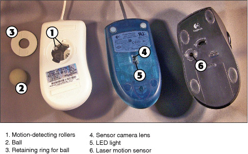
Most mice with mechanical sensors use a ball and roller design. The motion of the mouse ball against a mouse pad, desk, or tabletop can pick up dust and dirt that can cause erratic mouse-pointer movement. The ball and the rollers should be cleaned periodically. Clean the mouse with a specially designed mouse cleaning kit or use a nonabrasive damp cloth to remove gunk from the rollers and the ball.
To remove the mouse ball as shown in Figure 7-1 for access to the rollers, follow these steps
Step 1. Turn over the mouse; an access cover on the bottom of the mouse holds the ball in place.
Step 2. Follow the arrows on the access cover to turn or slide the cover to one side; lift the plate out of the way to release the ball.
Step 3. Turn the rollers until you see dirt or grit; wipe them clean and clean the ball.
Step 4. Shake loose dust and gunk out of the mouse.
Step 5. When you’ve finished the cleaning process, replace the ball and access panel.
Optical mice and laser mice do not require disassembly. To keep an optical mouse in proper working order, wipe dust and dirt away from the LED light and sensor camera lens. To keep a laser mouse working properly, wipe dust and dirt away from the laser.
For wireless mice, be sure to check batteries periodically for leakage, and replace batteries when the cursor action becomes erratic. For mice that use rechargeable batteries, be sure to use approved types and charge the batteries as recommended by the battery vendor.
To maintain trackballs, remove the trackball and clean the rollers to keep the trackball working properly.
To maintain touchpads, periodically wipe the surface with a dampened cloth to remove skin oils that can prevent proper sensing of finger movements.
Maintaining Keyboards
Keyboards can become unresponsive or erratic due to dust, dirt, and debris under the keytops, and the keytops can become dirty and sticky. Here’s how (and how not) to clean them:
Step 1. Don’t use sprays to clean a keyboard; use a cloth dampened with an antistatic surface cleaner to wipe off grime while the system is turned off.
Step 2. Use compressed air or a data-grade vacuum cleaner to remove dirt and dust under the keys, or remove the keys if possible for cleaning with compressed air or a data-grade vacuum cleaner.
Tip
If you’re not certain if the keytops can be removed, check with the keyboard vendor.
To remove the keytops from the keyboard, I recommend you use a chip puller, a U-shaped tool included with many computer toolkits. Grasp two sides of the keytop with the chip puller and lift it from the keyboard. If you don’t have a chip puller, use a pair of flat-bladed screwdrivers to carefully lift the keytop from opposite sides at once.
Exam Preparation Tasks
Review All the Key Topics
Review the most important topics in the chapter, noted with the key topics icon in the outer margin of the page. Table 7-13 lists a reference of these key topics and the page numbers on which each is found.
Table 7-13 Key Topics for Chapter 7

Complete the Tables and Lists from Memory
Print a copy of Appendix B, “Memory Tables,” (found on the CD), or at least the section for this chapter, and complete the tables and lists from memory. Appendix C, “Memory Tables Answer Key,” also on the CD, includes completed tables and lists to check your work.
Definitions of Key Terms
Define the following key terms from this chapter, and check your answers in the glossary.
USB,
SCSI,
LPT,
PS/2,
Troubleshooting Scenario
You have been asked about a printing issue on a specific computer. You have looked in the Windows Control Panel Printers and Faxes folder and determined that the printer is installed correctly. What procedure would you use to try to fix the problem?
Refer to Appendix A, “Answers to the ‘Do I Know This Already?’ Quizzes and Troubleshooting Scenarios,” for the answer.