
Chapter 3. Motherboards, Processors, and Adapter Cards
This chapter covers a portion of CompTIA A+ 220-701 objectives 1.2, 1.4, and 1.5, and CompTIA A+ 220-702 objectives 1.1 and 1.2.
In this chapter we’ll talk about some of the core components of the computer—the guts of the computer—including the motherboard, processor, and adapter cards. Everything connects to the motherboard, so it stands to reason that proper planning and design of a PC, to a certain degree, starts with this component. Just as important is the processor. The processor (or CPU) is the “brain” of the computer and takes care of the bulk of the PC’s calculations. Deciding on a CPU and motherboard should be the first tasks at hand when building a PC. Adapter cards are vital because they allow video, audio, and network capabilities. It is important to know how many and what type of adapter card slots are available on your motherboard before selecting specific adapter cards.
Within these pages you will learn how to install and troubleshoot motherboards, processors, and adapter cards and discover some of the considerations to take into account when building the core of a PC.
“Do I Know This Already?” Quiz
The “Do I Know This Already?” quiz allows you to assess whether you should read this entire chapter or simply jump to the “Exam Preparation Tasks” section for review. If you are in doubt, read the entire chapter. Table 3-1 outlines the major headings in this chapter and the corresponding “Do I Know This Already?” quiz questions. You can find the answers in Appendix A, “Answers to the ‘Do I Know This Already?’ Quizzes and Troubleshooting Scenarios.”
Table 3-1 “Do I Know This Already?” Foundation Topics Section-to-Question Mapping

1. The system bus and I/O bus carry four different types of signals throughout the computer. Which of the following are the signals? (Choose all that apply.)
a. Data
b. Power
c. Control
d. Adapters
e. Address
2. Which of the following are considered expansion slots? (Choose all that apply.)
a. PCI
b. FireWire
c. AGP
d. USB
3. Which of the following can you use with SCSI (Small Computer Systems Interface)? (Choose all that apply.)
a. Hard drives
b. Scanners
c. Laser printers
d. DVD-ROMs
e. A dot-matrix printer
4. Which of the following are in the ATX family of motherboards? (Choose all that apply.)
a. ATX
b. Mini-ATX
c. FlexATX
d. ATX and Mini-ATX only
e. None of the options provided is correct
5. Which of the following are considered integrated I/O ports?
a. Serial port
b. Parallel port
c. USB port
d. PS/2 mouse and keyboard
e. Audio port
f. Ethernet port
g. All of these options are correct
6. Which one of the listed processors was the last slot-based processor designed by Intel?
a. Celeron
b. Core 2 Duo
c. Pentium D
d. Pentium III
7. Which of the following processors was the first dual-core design by AMD?
a. Athlon 64 X2
b. Athlon
c. Duron
d. Sempron
8. Which of the following best describes hyperthreading?
a. Overclocking your CPU
b. Processing two execution threads simultaneously
c. Having more than one processor
d. None of these options is correct
9. Before you remove the processor from the motherboard, what device should you remove first?
a. Power supply
b. RAM chip
c. Heat sink
d. Thermal compound
10. You have been dispatched to a client’s computer. You have decided that the processor is overheating. Which of the following steps can you take to help with the air flow around the processor?
a. Blow it out with compressed air
b. Remove the heat sink from the CPU
c. Place it on a surface covered with old newspapers or waste paper
d. Clean off the old thermal paste and reapply a small amount to the processor
e. All of these options are correct
11. Which of the following are causes of overheating? (Choose all that apply.)
a. Fan failure
b. The power supply fan is too large
c. Incorrect heat sink
d. Incorrect processor
12. To connect speakers to the sound card, which of the following must you use?
a. 1/2-inch jack
b. 1 1/4-inch jack cable
c. 2/3-inch jack cable
d. 1/8-inch mini-jack cable
e. None of these options is correct
Foundation Topics
Motherboards and Their Components
The motherboard represents the logical foundation of the computer. In other words, everything that makes a computer a computer must be attached to the motherboard. From the CPU to storage devices, from RAM to printer ports, the motherboard provides the connections that help them work together.
Figure 3-1 A typical ATX motherboard with support for Nvidia’s scalable link interface (SLI) technology.
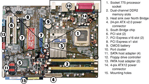
![]()
The motherboard is essential to computer operation in large part because of the two major buses it contains: the system bus and the I/O bus. Together, these buses carry all the information between the different parts of the computer.
The System Bus and I/O Bus
The system bus carries four different types of signals throughout the computer:
• Data
• Power
• Control
• Address
To help you understand this concept, let’s take an imaginary trip to Chicago and compare the city to a typical motherboard. If you were on the Willis Tower observation deck overlooking downtown Chicago one evening, you would first notice the endless stream of cars, trucks, and trains carrying people and goods from everywhere to everywhere else along well-defined surface routes (the expressways and tollways, commuter railroads, Amtrak, and airports). You can compare these routes to the data bus portion of the system bus, which carries information between RAM and the CPU. If you’ve ever listened to the traffic reports on a radio station such as Chicago’s WBBM (760 AM), you’ve heard how traffic slows down when expressway lanes are blocked by construction or stalled traffic. In your computer, wider data buses that enable more “lanes” of data to flow at the same time promote faster system performance.
Now, imagine that you’ve descended to street level, and you’ve met with a local utility worker for a tour of underground Chicago. On your tour, you will find an elaborate network of electric and gas lines beneath the street carrying the energy needed to power the city. You can compare these to the power lines in the system bus, which transfer power from the motherboard’s connection to the power supply to the integrated circuits (ICs or chips) and expansion boards connected to the motherboard.
Go back to street level, and notice the traffic lights used both on city streets and on the entrance ramps to busy expressways, such as the Eisenhower and the Dan Ryan. Traffic stops and starts in response to the signals. Look at the elevated trains or at the Metra commuter trains and Amtrak intercity trains; they also move as directed by signal lights. These signals, which control the movement of road and rail traffic, can be compared to the control lines in the system bus, which control the transmission and movement of information between devices connected to the motherboard.
Finally, as you look around downtown, take a close look at the men and women toting blue bags around their shoulders or driving electric vans and Jeeps around the city. As these mail carriers deliver parcels and letters, they must verify the correct street and suite addresses for the mail they deliver. They correspond to the address bus, which is used to “pick up” information from the correct memory location among the gigabytes of RAM in computer systems and “deliver” new programs and changes back to the correct memory locations.
The I/O bus connects storage devices to the system bus and can be compared to the daily flow of commuters and travelers into the city in the morning, and out again in the evening. Between them, the system and I/O buses carry every signal throughout the motherboard and to every component connected to the motherboard.
Form Factors
Although all motherboards have some features in common, their layout and size varies a great deal. The most common motherboard designs in current use include ATX, Micro ATX, BTX, and NLX. Some of these designs feature riser cards and daughterboards. The following sections cover the details of these designs.
ATX and Micro ATX
The ATX family of motherboards has dominated desktop computer designs since the late 1990s. ATX stands for “Advanced Technology Extended,” and it replaced the AT and Baby-AT form factors developed in the mid 1980s for the IBM PC AT and its rivals. ATX motherboards have the following characteristics:
• A rear port cluster for I/O ports
• Expansion slots that run parallel to the short side of the motherboard
• Left side case opening (as viewed from the front of a tower PC)
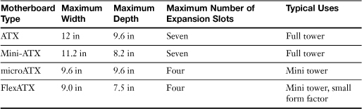
There are four members of the ATX family, listed in Table 3-2. In practice, though, the Mini-ATX design is not widely used.
Table 3-2 ATX Motherboard Family Comparison
BTX
One problem with the ATX design has been the issue of system cooling. Because ATX was designed more than a decade ago, well before the development of today’s faster components, it’s been difficult to properly cool the hottest-running components in a typical system: the processor, memory modules, and the processor’s voltage regulator circuits.
To enable better cooling for these devices, and to promote better system stability, the BTX family of motherboard designs was introduced in 2004. Compared to ATX motherboards, BTX motherboards have the following:
• Heat-producing components such as the process, memory, chipset, and voltage regulator are relocated to provide straight-through airflow from front to back for better cooling.
• The processor socket is mounted at a 45-degree angle to the front of the motherboard to improve cooling.
• A thermal module with a horizontal fan fits over the processor for cooling.
• The port cluster is moved to the rear left corner of the motherboard.
• BTX cases include multiple rear and side air vents for better cooling.
• Because of the standardization of processor and memory locations, it’s easy to use the same basic design for various sizes of BTX motherboards; the designer can just add slots.
• BTX tower cases use a right-opening design as viewed from the front.
Although BTX designs are easier to cool than ATX designs, the development of cooler-running processors has enabled system designers to continue to favor ATX. There are relatively few BTX-based motherboards and systems currently on the market.
Figure 3-2 compares typical ATX and BTX motherboard layouts to each other.
Figure 3-2 The ATX motherboard family includes ATX (largest), microATX, and flexATX (smallest). The BTX motherboard family includes BTX, microBTX, nanoBTX, and picoBTX (smallest).
Note
The motherboard examples shown in Figure 3-2 are simplified examples of actual motherboards. Onboard ports, port headers, and additional motherboard power connectors are not shown. Also, motherboards using a particular design might have components in slightly different positions than shown here.
NLX
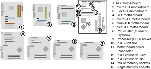
NLX motherboards are designed for quick replacement in corporate environments. They use a riser card that provides power and expansion slots that connect to the right edge of the motherboard (as viewed from the front). NLX motherboards have a two-row cluster of ports along the rear edge of the motherboard.
Most systems that use NLX motherboards are considered obsolete. Figure 3-3 illustrates a typical NLX motherboard and riser card.
Figure 3-3 A typical NLX motherboard and riser card.
Riser Cards and Daughterboards
Riser cards and daughterboards provide two different methods for providing access to motherboard–based resources. In current slimline or rackmounted systems based on ATX or BTX technologies, riser cards are used to make expansion slots usable that would otherwise not be available because of clearances inside the case. Riser card designs can include one or more expansion slots, and are available in PCI, PCI-X (used primarily in workstation and server designs), and PCI-Express designs. Figure 3-4 shows two typical implementations of riser card designs.
Figure 3-4 Examples of single-slot and multi-slot riser cards.

The term daughterboard is sometimes used to refer to riser cards, but daughterboard can also refer to a circuit board that plugs into another board to provide extra functionality. For example, some small form factor motherboards support daughterboards that add additional serial or Ethernet ports, and some standard-size motherboards use daughterboards for their voltage regulators.
Integrated I/O Ports
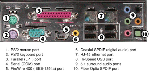
Motherboards in both the ATX and BTX families feature a variety of integrated I/O ports. These are found in as many as three locations: all motherboards feature a rear port cluster (see Figure 3-5 for a typical example), and many motherboards also have additional ports on the top of the motherboard that are routed to header cables accessible from the front and rear of the system.
Figure 3-5 A port cluster on a late-model ATX system.
![]()
Most recent motherboards include the following ports in their port cluster:
• Serial (COM)
• PS/2 mouse
• PS/2 keyboard
• USB 2.0 (Hi-Speed USB)
• 10/100 or 10/100/1000 Ethernet (RJ-45)
• Audio
So-called “legacy-free” motherboards might omit some or all of the legacy ports (serial, parallel, PS/2 mouse and keyboard), a trend that will continue as devices using these ports have been replaced by devices that plug into USB ports.
Some high-end systems might also include one or more FireWire (IEEE-1394a) ports, and systems with integrated video include a VGA or DVI-I video port and an S-Video or HDMI port for TV and home theater use.
Figure 3-5 illustrates a port cluster from a typical ATX system, but note that BTX systems use similar designs.
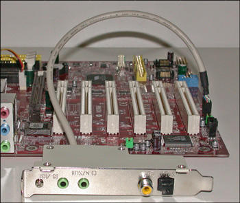
Some integrated ports use header cables to provide output. Figure 3-6 shows an example of 5.1 surround audio ports on a header cable. The header cable plugs into the motherboard and occupies an empty expansion slot.
Figure 3-6 This header cable provides support for 5.1 surround analog audio and digital audio.
Memory Slots
Modern motherboards include two or more memory slots, as seen in Figures 3-1 and 3-2. At least one memory slot must contain a memory module, or the system cannot start or function.
Memory slots vary in design according to the type of memory the system supports. Older systems that use SDRAM use three-section memory slots designed for 168-pin memory modules. Systems that use DDR SDRAM use two-section memory slots designed for 184-pin modules. Systems that use DDR2 SDRAM use two-section memory slots designed for 240-pin modules.
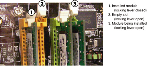
Each memory slot includes locking levers that secure memory in place. When memory is properly installed, the levers automatically swivel into place (see Figure 3-7).
Figure 3-7 Installing memory modules.
To learn more about memory types and slots, see Chapter 6, “RAM.”
Expansion Slots
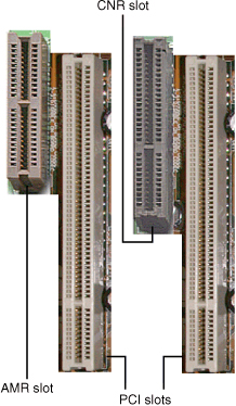
Motherboards use expansion slots to provide support for additional I/O devices and high-speed video/graphics cards. The most common expansion slots on recent systems include peripheral component interconnect (PCI), advanced graphics port (AGP), and PCI-Express (also known as PCIe). Some systems also feature audio modem riser (AMR) or communications network riser (CNR) slots for specific purposes.
PCI Slots
The PCI slot can be used for many types of add-on cards, including network, video, audio, I/O and storage host adapters for SCSI, PATA, and SATA drives. There are several types of PCI slots, but the one found in desktop computers is the 32-bit slot running at 33MHz (refer to Figure 3-8 in the next section).
Figure 3-8 PCI slots compared to an AGP 1x/2x slot (top), an AGP 4x/8x slot (middle), and an AGP Pro/Universal slot (bottom).

![]()
AGP
The AGP slot was introduced as a dedicated slot for high-speed video (3D graphics display) in 1996. Since 2005, the PCI Express x16 slot (described in the next section) has replaced it in most new systems. There have been several versions of the AGP slot, reflecting changes in the AGP standard, as shown in Figure 3-8. Note that all types of AGP slots can temporarily “borrow” system memory when creating 3D textures.
Note that the AGP 1x/2x and AGP 4x/8x slots have their keys in different positions. This prevents installing the wrong type of AGP card into the slot. AGP 1x/2x cards use 3.3V, whereas most AGP 4x cards use 1.5V. AGP 8x cards use 0.8 or 1.5V. The AGP Pro/Universal slot is longer than a normal AGP slot to support the greater electrical requirements of AGP Pro cards (which are used in technical workstations). The protective cover over a part of the slot is intended to prevent normal AGP cards from being inserted into the wrong part of the slot. The slot is referred to as a universal slot because it supports both 3.3V and 1.5V AGP cards.
Caution
An AGP Pro slot cover might be removed after a system has been in service for awhile, even if an AGP Pro card wasn’t inserted in a computer. If you see an AGP Pro slot without a cover and you’re preparing to install an AGP card, cover the extension with a sticker to prevent damaging a standard AGP card by inserting it improperly.
PCIe (PCI-Express) Slots
PCI Express (often abbreviated as PCIe or PCIE) began to replace both PCI and AGP slots in new system designs starting in 2005. PCI Express slots are available in four types:
• x1
• x4
• x8
• x16
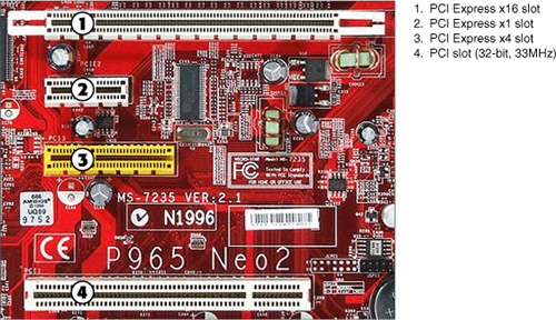
The most common versions include the x1, x4, and x16 designs, as shown in Figure 3-9.
Figure 3-9 PCI Express slots compared to a PCI slot.
![]()
PCI Express x1 and x4 slots are designed to replace the PCI slot, and x8 and x16 are designed to replace the AGP slot. Table 3-3 compares the performance of PCI, AGP, and PCI Express slots.
Table 3-3 Technical Information About Expansion Slot Types

Note
At the time of publication of this book, there are three versions of PCI Express. V1.0 is rated at 250MB/s per lane, V2.0 at 500 MB/s, and V3.0 at 1GB/s with a maximum of 32 lanes.
*The data rates listed in Table 3-3 are the bidirectional (simultaneous send/receive) throughput amounts you should know for the exam. Unidirectional data rates (send or receive) are one-half of the bidirectional data rates.
SLI is the NVIDIA method for using two or more graphics cards to render 3D game graphics
CrossFire is the ATI/AMD method for using two or more graphics cards to render 3D game graphics.
AMR and CNR Slots
Some motherboards have one of two specialized expansion slots in addition to the standard PCI, PCI Express, or AGP slots. The audio modem riser (AMR) slot (see Figure 3-10) enables motherboard designers to place analog modem and audio connectors and the codec chip used to translate between analog and digital signals on a small riser card. AMR slots are frequently found on older systems with chipsets that integrate software modems (see Figure 3-11) and audio functions.
Figure 3-10 An AMR slot and PCI slot (left) compared to a CNR slot and PCI slot (right). Very few AMR riser cards were ever sold, but some motherboard vendors have bundled CNR riser cards with their motherboards to provide six-channel audio output and other features.
![]()
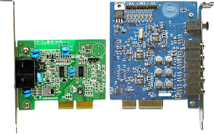
Figure 3-11 An AMR riser card used for soft modem support (left) and a CNR riser card used for six-channel (5.1) analog and digital audio support (right).
![]()
The AMR was replaced by the communications network riser (CNR) slot (see Figure 3-10), a longer design that can support up to six-channel audio, S/PDIF digital audio, and home networking functions. Some vendors have used the CNR slot to implement high-quality integrated audio as shown in Figure 3-11.
The AMR or CNR slot, when present, is usually located on the edge of the motherboard. The AMR slot was often found on Pentium III or AMD Athlon-based systems, while the CNR slot was used by some Pentium 4-based systems. Current systems integrate network and audio features directly into the motherboard and its port cluster, making both types of slots obsolete.
Note
AMR and CNR riser cards were generally provided by motherboard makers because they are customized to the design of particular motherboards. Although some parts suppliers have sold AMR and CNR cards separately, it’s best to get the riser card from the same vendor as the motherboard to ensure proper hardware compatibility and driver support.
To learn more about PCI, PCIe, and AGP slots when used for graphics cards, see Chapter 8, “Video Displays and Graphics Cards.” To learn more about installing adapter cards, see “Installing Adapter Cards,” later in this chapter.
Mass Storage Interfaces
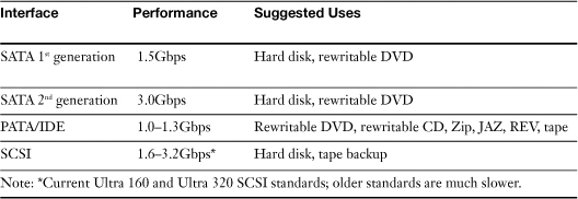
Motherboards also include mass storage interfaces such as EIDE/PATA, SATA, and SCSI. The following sections compare and contrast the appearance and functionality of these interfaces. Table 3-4 provides a quick overview of technical information about these interfaces.
Table 3-4 Technical Information About Mass Storage Interfaces
![]()
EIDE/PATA
Until recently, most motherboards included two or more EIDE/PATA (also known as ATA/IDE) host adapters for PATA devices such as hard disks, CD or DVD drives, tape backups, and removable-media drives. Each host adapter uses a 40-pin interface similar to the one shown in Figure 3-12, and can control up to two drives.
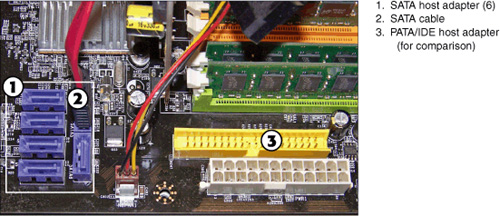
Figure 3-12 PATA and SATA host adapters on a typical motherboard.
![]()
Most recent systems use a plastic skirt around the PATA connector with a notch on one side. This prevents improper insertion of a keyed PATA (ATA/IDE) cable. However, keep in mind that some older systems have unskirted connectors and some older ATA/IDE cables are not keyed. To avoid incorrect cable connections, be sure to match pin 1 on the PATA host adapter to the red-striped edge of the PATA ribbon cable.
On systems with a third EIDE/PATA host adapter, the additional host adapter is typically used for a RAID 0 or RAID 1 drive array. See your system or motherboard documentation for details. Most current systems now have only one EIDE/PATA host adapter, as the industry is transitioning away from EIDE/PATA to SATA interfaces for both hard disk and DVD drives.
SATA
Most recent systems have anywhere from two to as many as eight Serial ATA (SATA) host adapters. Each host adapter controls a single SATA drive, such as a hard disk or rewritable DVD drive.
The original SATA host adapter design did not have a skirt around the connector, making it easy for the cable to become loose. Many late-model systems now use a skirted design for the host adapter (see Figure 3-13).
Figure 3-13 Most late model systems include multiple SATA host adapters with skirted connectors.
SCSI
SCSI (Small Computer Systems Interface) is a more flexible drive interface than PATA (ATA/IDE) because it can accommodate many devices that are not hard disk drives. The following have been common uses for SCSI:
• High-performance and high-capacity hard drives
• Image scanners
• Removable-media drives such as Zip, Jaz, and Castlewood Orb
• High-performance laser printers
• High-performance optical drives, including CD-ROM, CD-R, CD-RW, DVD-ROM, and others
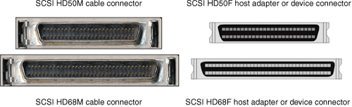
So-called Narrow SCSI host adapters (which use an 8-bit data channel) can accommodate up to seven devices of different varieties on a single connector on the host adapter through daisy-chaining. Wide SCSI host adapters use a 16-bit data channel and accommodate up to 15 devices on a single connector on the host adapter through daisy-chaining. Narrow SCSI devices and host adapters use a 50-pin or (rarely) a 25-pin cable and connector, while Wide SCSI devices use a 68-pin cable and connector.
Several years ago, SCSI host adapters were found on some high-end desktop and workstation motherboards. However, most recent systems use SATA in place of SCSI, and SCSI host adapters and devices are now primarily used by servers. Currently, SCSI is used primarily for high-performance hard disks and tape backups.
Systems with onboard SCSI host adapters might have one or more 50-pin or 68-pin female connectors similar to those shown in Figure 3-14.
Figure 3-14 SCSI HD50 and HD68 cables and connectors are typically used on systems with onboard SCSI host adapters.
To learn more about storage devices, see Chapter 12, “Storage Devices.”
Choosing the Best Motherboard for the Job
So, how do you go about choosing the best motherboard for the job? Follow this process:
Step 1. Decide what you want the motherboard (system) to do. Because most of a computer’s capabilities and features are based on the motherboard, you need to decide this first.
Some examples:
If you need high CPU performance, you must choose a motherboard that supports the fastest dual-core or multi-core processors available. If you want to run a 64-bit (x64) operating system, you need a motherboard that supports 64-bit processors and more than 4GB of RAM. If you want to run fast 3D gaming graphics, you need a motherboard that supports NVIDIA’s SLI or ATI’s CrossFire multi-GPU technologies. If you want to support multimedia uses such as video editing, you’ll prefer a motherboard with onboard IEEE-1394a (FireWire 400). If you are building a system for use as a home theater, a system with HDMI graphics might be your preferred choice.
Step 2. Decide what form factor you need to use. If you are replacing an existing motherboard, the new motherboard must fit into the case (chassis) being vacated by the old motherboard and (ideally) be powered by the existing power supply. If you are building a new system, though, you can choose the form factor needed.
Some examples:
Full-size ATX or BTX motherboards provide the most room for expansion but require mid-size or full-size tower cases. If no more than three expansion slots are needed, micro ATX or micro BTX systems fit into mini-tower cases that require less space and can use smaller, less-expensive power supplies. If only one slot (or no slots) are needed, picoATX or picoBTX systems that fit into small form factor cases require very little space.
Installing Motherboards
What keeps a motherboard from sliding around inside the case? If you look at an unmounted motherboard from the top, you can see that motherboards have several holes around the edges and one or two holes toward the middle of the motherboard. Most ATX-family and BTX-family motherboards are held in place by screws that are fastened to brass spacers that are threaded into holes in the case or a removable motherboard tray. Before you start working with motherboards or other static-sensitive parts, see the section “Electrostatic Discharge (ESD),” in Chapter 17, “Safety and Environmental Issues,” for ESD and other precautions you should follow.
Step-by-Step Motherboard Removal (ATX and BTX)
Removing the motherboard is an important task for the computer technician. For safety’s sake, you should remove the motherboard before you install a processor upgrade as well as if you need to perform a motherboard upgrade.
To remove ATX or BTX-family motherboards from standard cases, follow these steps:
Step 1. Turn off the power switch and disconnect the AC power cable from the power supply.
Step 2. Disconnect all external and internal cables attached to add-on cards after labeling them for easy reconnection.
Step 3. Disconnect all ribbon cables attached to built-in ports on the motherboard (I/O, storage, and so on) after labeling them for easy reconnection.
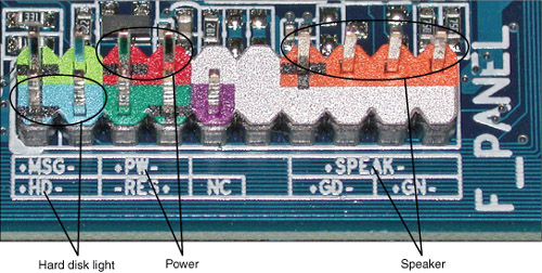
Step 4. Disconnect all cables leading to internal speakers, key locks, speed switches, and other front-panel cables. Most recent systems use clearly marked cables as shown in Figure 3-15, but if the cables are not marked, mark them before you disconnect them so you can easily reconnect them later.
Figure 3-15 Front-panel cables attached to a typical motherboard, which control system power to the motherboard, case speaker, drive and power lights, and so on.

Tip
You can purchase premade labels for common types of cables, but if these are not available, you can use a label maker or blank address labels to custom-make your own labels.
Step 5. Remove all add-on cards and place them on an antistatic mat or in (not on top of) antistatic bags.
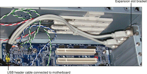
Step 6. Disconnect header cables from front- or rear-mounted ports and remove them from the system (see Figure 3-16).
Figure 3-16 A typical dual-USB header cable that uses an expansion slot bracket.
Step 7. Disconnect the power-supply leads from the motherboard. The new motherboard must use the same power-supply connections as the current motherboard. See Chapter 5, “Power Supplies and System Cooling,” for details about power supply connections.
Step 8. Remove the heat sink and the processor before you remove the motherboard and place them on an anti-static mat. Removing these items before you remove the motherboard helps prevent excessive flexing of the motherboard and makes it easier to slip the motherboard out of the case. However, skip this step if the heat sink requires a lot of downward pressure to remove and if the motherboard is not well supported around the heat sink/processor area.
Step 9. Unscrew the motherboard mounting screws (refer to Figure 3-1) and store for reuse; verify that all screws have been removed.
Caution
Easy does it with the screwdriver! Whether you’re removing screws or putting them back in, skip the electric model and do it the old-fashioned way to avoid damaging the motherboard. If your motherboard is held in place with hex screws, use a hex driver instead of a screwdriver to be even more careful.
Step 10. Lift the motherboard and plastic stand-off spacers out of the case and place them on an antistatic mat. Remove the I/O shield (the metal plate on the rear of the system which has cutouts for the built-in ports; refer to Figure 3-17) and store it with the old motherboard.
Figure 3-17 An ATX I/O shield and motherboard during installation.

Step-by-Step Motherboard Removal (NLX)
NLX motherboards are designed for fast, easy removal. Follow this procedure:
Step 1. As described earlier, disconnect cables from any installed add-on cards.
Step 2. Remove any add-on cards, remembering to handle the cards by their edges.
Step 3. Pull the motherboard release lever to disconnect the motherboard from the NLX riser.
Step 4. Slide the motherboard out of the case.
Preparing the Motherboard for Installation (ATX/BTX)
Before you install the new motherboard into the computer, perform the following steps:
Step 1. Review the manual supplied with the new motherboard to determine correct sizes of memory supported, processor types supported, and configuration information.
Step 2. Install the desired amount of memory. See Chapter 6, “RAM,” for details.
Step 3. Install the processor (CPU) and heat sink as described later in this chapter.
Step 4. Configure CPU speed, multiplier, type, and voltage settings on the motherboard if the motherboard uses jumpers or DIP (Dual Inline Pin) switches. Note that many recent motherboards use BIOS configuration options instead.
To learn more about configuring the motherboard for a particular CPU, see the section “Processors and CPUs” later in this chapter.
Making these changes after the motherboard is installed in the computer is normally very difficult.
Step-by-Step Motherboard Installation (ATX/Baby-AT)
After you have prepared the motherboard for installation, follow these steps to install the motherboard:
Step 1. Place the new motherboard over the old motherboard to determine which mounting holes should be used for standoffs (if needed) and which should be used for brass spacers. Matching the motherboards helps you determine that the new motherboard will fit correctly in the system.
Step 2. Move brass spacers as needed to accommodate the mounting holes in the motherboard.
Step 3. Place the I/O shield and connector at the back of the case. The I/O shield is marked to help you determine the port types on the rear of the motherboard. If the port cutouts on some I/O shields are not completely removed, remove them before you install the shield.
Step 4. Determine which holes in the motherboard have brass stand-off spacers beneath them and secure the motherboard using the screws removed from the old motherboard (see Figure 3-17).
Step 5. Reattach the wires to the speaker, reset switch, IDE host adapter, and power lights.
Step 6. Reattach the ribbon cables from the drives to the motherboard’s IDE and floppy disk drive interfaces. Match the ribbon cable’s colored side to pin 1 on the interfaces.
Step 7. Reattach cables from the SATA drives to the SATA ports on the motherboard. Use SATA port 1 for the first SATA drive, and so on.
Step 8. Reattach the power supply connectors to the motherboard.
Step 9. Insert the add-on cards you removed from the old motherboard; make sure your existing cards don’t duplicate any features found on the new motherboard (such as sound, ATA/IDE host adapters, and so on). If they do, and you want to continue to use the card, you must disable the corresponding feature on the motherboard.
Step 10. Mount header cables that use expansion card slot brackets into empty slots and connect the header cables to the appropriate ports on the motherboard.
Step 11. Attach any cables used by front-mounted ports such as USB, serial, or IEEE-1394 ports to the motherboard and case.
Step-by-Step Motherboard Installation (NLX)
After you have prepared the motherboard for installation, follow these steps to install the motherboard:
Step 1. Line up the replacement motherboard with the motherboard rails located at the bottom of the case.
Step 2. Slowly push the motherboard into place. After the motherboard is connected to the riser card, it stops moving.
Step 3. Lift and push the motherboard release lever to lock the motherboard into place.
Step 4. Replace the side panel. If the side panel cannot be replaced properly, the motherboard is not installed properly.
Troubleshooting Motherboards
When you’re troubleshooting a computer, there is no shortage of places to look for problems. However, because the motherboard is the “home” for the most essential system resources, it’s often the source of many problems. If you see the following problems, consider the motherboard as a likely place to look for the cause:
• System will not start— When you push the power button on an ATX or BTX system, the computer should start immediately. If it doesn’t, the problem could be motherboard–related.
• Devices connected to the port cluster don’t work— If ports in the port cluster are damaged or disabled in the system BIOS configuration (CMOS setup), any devices connected to the port cluster will not work.
• Devices connected to header cables don’t work— If ports connected to the header are not plugged into the motherboard, are damaged, or are disabled in the system BIOS configuration (CMOS setup), any devices connected to these ports will not work.
• Mass storage drives are not recognized or do not work— If mass storage ports on the motherboard are not properly connected to devices, are disabled, or are not configured properly, drives connected to these ports will not work.
• Memory failures— Memory failures could be caused by the modules themselves, or they could be caused by the motherboard.
• Problems installing aftermarket processor heat sinks or replacement cards— You cannot assume that every device fits every system.
The following sections help you deal with these common problems.
System Will Not Start
If the computer will not start, check the following:
• Incorrect front panel wiring connections to the motherboard
• Loose or missing power leads from power supply
• Loose or missing memory modules
• Loose BIOS chips
• Incorrect connection of PATA/IDE cables to onboard host adapter
• Dead short in system
• Incorrect positioning of a standoff
• Loose screws or slot covers
The following sections describe each of these possible problems.
Incorrect Front Panel Wiring Connections to the Motherboard
The power switch is wired to the motherboard, which in turn signals the power supply to start. If the power lead is plugged into the wrong pins on the motherboard, or has been disconnected from the motherboard, the system will not start and you will not see an error message.
Check the markings on the front panel connectors, the motherboard, or the motherboard/system manual to determine the correct pinouts and installation. Figure 3-18 shows typical motherboard markings for front panel connectors (refer to Figure 3-15 for typical markings on front-panel wires).
Figure 3-18 A typical two-row front panel connector on a motherboard.
Loose or Missing Power Leads from Power Supply
Modern power supplies often have both a 20- or 24-pin connection and a four- or eight-pin connection to the motherboard. If either or both connections are loose or not present, the system cannot start and you will not see an error message.
For details, see Chapter 5, “Power Supplies and System Cooling.”
Loose or Missing Memory Modules
If the motherboard is unable to recognize any system memory, it will not start properly. Unlike the other problems, you will see a memory error message.
Make sure memory modules are properly locked into place, and that there is no corrosion on the memory contacts on the motherboard or on the memory modules themselves. To remove corrosion from memory module contacts, remove the memory modules from the motherboard and gently wipe the contacts off to remove any built-up film or corrosion. An Artgum eraser (but not the conventional rubber or highly abrasive ink eraser) can be used for stubborn cases. Be sure to rub in a direction away from the memory chips to avoid damage. Reinsert the modules and lock them into place.
Caution
Never mix tin memory sockets and gold memory module connectors, or vice versa. Using different metals for memory socket and module connectors has been a leading cause of corrosion with SIMM-based systems.
Loose BIOS Chips
Socketed motherboard chips that don’t have retaining mechanisms, such as BIOS chips, can cause system failures if the chips work loose from their sockets. The motherboard BIOS chip (see Figure 3-19) is responsible for displaying boot errors, and if it is not properly mounted in its socket, the system cannot start and no error messages will be produced (note that many recent systems have surface-mounted BIOS chips).
Figure 3-19 If a socketed BIOS chip like this one becomes loose, the system will not boot.

The cycle of heating (during operation) and cooling (after the power is shut down) can lead to chip creep, in which socketed chips gradually loosen in the sockets. To cure chip creep, push the chips back into their sockets. Use even force to press a square BIOS chip into place. On older systems that use rectangular BIOS chips, alternately push on each end of the chip until the chip is securely mounted.
Note
Check your system or motherboard documentation to determine the location of the BIOS chip.
Incorrect Connection of PATA/IDE Cables to Onboard Host Adapter
Many systems are designed to wait for a response from a device connected to a PATA/IDE host adapter on the motherboard before continuing to boot. If the PATA/IDE cable is plugged in incorrectly, the system will never get the needed response, and some systems will not display an error message.
Make sure pin 1 on the cable is connected to pin 1 on the PATA/IDE device and the corresponding host adapter on the system. Check the motherboard manual for the position of pin 1 on the motherboard’s host adapter if the host adapter is not marked properly.
Dead Short (Short Circuit) in System
A dead short (short circuit) in your system will prevent a computer from showing any signs of life when you turn it on. Some of the main causes for dead shorts that involve motherboards include
• Incorrect positioning of a standoff
• Loose screws or slot covers
The following sections describe both possible causes.
Incorrect positioning of a standoff
Brass standoffs should be lined up with the mounting holes in the motherboard (refer to Figure 3-1 for typical locations). Some motherboards have two types of holes: plain holes that are not intended for use with brass standoffs (they might be used for heat sink mounting or for plastic standoffs) and reinforced holes used for brass standoffs. Figure 3.20 compares these hole types.
Figure 3-20 Mounting holes compared to other holes on a typical motherboard.
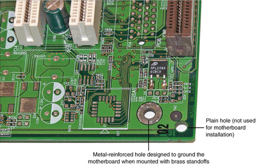
If a brass standoff is under a part of the motherboard not meant for mounting, such as under a plain hole or under the solder connections, the standoff could cause a dead short that prevents the system from starting.
Loose screws or slot covers
Leaving a loose screw inside the system and failing to fasten a slot cover or card in place are two common causes for dead shorts, because if these metal parts touch live components on the motherboard, your system will short out and stop working.
The solution is to open the case and remove or secure any loose metal parts inside the system. Dead shorts also can be caused by power supply–related problems.
For more about the power supply and dead shorts, see “Troubleshooting Power Problems” in Chapter 5.
Devices Connected to the Port Cluster Don’t Work
The port cluster (refer to Figure 3-5) provides a “one–stop shop” for most I/O devices, but if devices plugged into these ports fail, check the disabled ports and possible damage to a port in the port cluster, as described in the following sections.
Disabled Port
If a port hasn’t been used before, and a device connected to it doesn’t work, be sure to check the system’s BIOS configuration to determine if the port is disabled. This is a particularly good idea if the port is a legacy port (serial/COM, parallel/LPT) or is the second network port. Ports can also be disabled using Windows Device Manager.
To learn how to manage integrated ports using the system BIOS setup, see Chapter 4. To learn how to manage hardware using Windows Device Manager, see Chapter 15, “Troubleshooting and Maintaining Windows.”
Damage to a Port in the Port Cluster
If a port in the port cluster has missing or bent pins, it’s obvious that the port is damaged, but don’t expect all types of damage to be obvious. The easiest way to see if a port in the port cluster is damaged is to follow these steps:
Step 1. Verify that the port is enabled in the system BIOS and Windows Device Manager.
Step 2. Make sure the device cable is connected tightly to the appropriate port. Use the thumbscrews provided with serial/COM, parallel/LPT, and VGA or DVI video cables to assure a proper connection.
Step 3. If the device fails, try the device on another port or another system. If the device works, the port is defective. If the device doesn’t work, the device or the device’s cable is defective.
To solve the problem of a defective port, use one of these solutions:
• Replace the motherboard with an identical model— This is the best solution for long-term use. Note that if you replace the motherboard with a different model you might need to reinstall Windows, or, at a minimum, reinstall drivers and reactivate Windows and some applications.
• Install an add-on card to replace the damaged port— This is quicker than replacing the motherboard, but if you are replacing a legacy port such as serial/COM or parallel/LPT, it can be expensive. If the device that plugged into a legacy port can also use a USB port, use a USB port instead.
• Use a USB/legacy port adapter— Port adapters can be used to convert serial/COM or parallel/LPT devices to work on USB ports. However, note that some limitations might be present. Generally, this is the least desirable solution.
Devices Connected to Header Cables Don’t Work
Before assuming that a port that uses a header cable is defective or disabled, make sure the header cable is properly connected to the motherboard. If the system has just been assembled, or if the system has recently undergone internal upgrades or servicing, it’s possible the header cable is loose or disconnected.
If the header cable is properly connected to the motherboard, follow the steps in the previous section to determine the problem and solution.
Note
Check system or motherboard documentation to determine how to properly connect header cables to the motherboard.
Mass Storage Devices Do Not Work Properly
Mass storage devices that connect to SATA, PATA/IDE, or SCSI host adapters on the motherboard will not work if either of the following are true, as described in the next sections:
• Mass storage ports are disabled in system BIOS or Windows
• Data cables are not properly connected to the motherboard or drives
Mass Storage Ports Disabled in System BIOS or Windows
Before assuming a mass storage device is defective, be sure to verify whether the port has been disabled in the system BIOS configuration (CMOS setup or in Windows Device Manager). If you cannot connect the device to another port, enable the port and retry the device. To learn how to manage integrated ports using the system BIOS setup, see Chapter 4. To learn how to manage hardware using the Windows Device Manager, see Chapter 15.
Data or Power Cables Are Not Properly Connected to the Motherboard or Drives
If internal upgrades or servicing has taken place recently, it’s possible that data or power cables have become loose or disconnected from the mass storage host adapters on the motherboard or the drives themselves. Before reconnecting the cables, shut down the computer and disconnect it from AC power.
For more about mass storage devices and cabling, see Chapter 12.
Memory Failures
Memory failures could be caused by the modules themselves, or they could be caused by the motherboard. For more information on memory problems and motherboards, see the section “Loose or Missing Memory Modules,” earlier in this chapter.
Card, Memory, or Heat Sink Blocked by Motherboard Layout
Internal clearances in late-model systems are very tight, and if you attempt to install some types of hardware in some systems, such as an oversized processor heat sink or a very large video card, it might not be possible because of the motherboard’s layout.
Before purchasing an aftermarket heat sink, check the clearances around the processor. Be especially aware of the location of capacitors and the voltage regulator; if the heat sink is too large, it could damage these components during installation. To help verify that an aftermarket heat sink will fit properly, remove the original heat sink from the processor and take it with you to compare its size to the aftermarket models you are considering.
Before purchasing an expansion card, check the slot clearance to be sure the card will fit into the desired expansion slot. In some cases, you might need to move a card from a neighboring slot to make room for the cooling fan shroud on some high-performance graphics cards.
Processors and CPUs
To do well on A+ Certification exams, you must understand the major types of processors available for recent systems, their technologies, how to install them, and how to troubleshoot them.
Overview of Processor Differences
Although Intel and AMD processors share two common architectures, x86 (used for 32-bit processors and for 64-bit processors running in 32-bit mode) and x64 (an extension of x86 that enables larger files, larger memory sizes, and more complex programs), these processor families differ in many ways from each other, including:
• Different processor sockets
• Different types of microcode
• Differences in dual-core and multi-core designs
• Cache sizes
• Performance versus clock speed
Intel Processors
Intel processors developed from 2000 to the present include the following product families:
• Pentium III
• Pentium 4
• Pentium D
• Celeron
• Core 2 Duo
• Core 2 Quad
Note
Intel’s Centrino technology refers to a combination of the Core 2 Duo and certain Intel chipsets made for mobile computers.
The Pentium III processor was the last Intel processor produced in both a slot-based and socket-based design. Slot-based versions use Slot 1, the same slot design used by the Pentium II and slot-based Celeron processors. Socketed versions use Socket 370, which is mechanically the same as the socket used by the first socketed Celeron processors. However, some early Socket 370 motherboards are not electrically compatible with the Pentium III.
The Pentium 4 replaced the Pentium III and ran at much higher clock speeds. Early versions used Socket 423, a socket used by no other Intel processor. Most Pentium 4 designs used Socket 478, while late-model Pentium 4 designs used Socket 775, which is also used by current Intel processors. The different sockets used by the Pentium 4 were necessary because of substantial design changes throughout the processor’s lifespan, including the introduction of 64-bit extensions (x64).
The Pentium 4’s successor was the Pentium D, which is essentially two Pentium 4 processor cores built into a single physical processor. Although it used the same Socket 775 as late-model Pentium 4 processors, it required support from different chipsets because data was transferred between processor cores via the Memory Controller Hub (North Bridge) component. The Pentium D was Intel’s first dual-core processor. The Pentium Extreme Edition is a faster version of the Pentium D designed for gaming or other high-performance tasks. The Pentium D and Pentium Extreme Edition both support x64 extensions, as does the Core 2 Duo.
The Pentium D was replaced by the Core 2 family of processors, which is the most recent Intel processor family covered on the A+ Certification exams. The Core 2 family switched to a new processor architecture that emphasizes real-world performance over clock speed. The first Core 2 processors were the Core 2 Duo (featuring two processor cores), followed by the Core 2 Quad models with four processor cores. Although Core 2 processors run at much slower clock speeds than the fastest Pentium 4 or Pentium D processors, they perform much better in real-world operations.
Celeron is actually a brand name rather than a specific processor design. Celeron processors have been based on the Pentium II, Pentium III, Pentium 4, and Core 2 processors. However, they feature lower clock speeds, slower front side bus speeds (the clock speed of the memory bus), and smaller L2 caches, making them less powerful (and less expensive) processors than the designs they’re based on. Very few Celeron models support x64 extensions.
Because most Intel processor families have gone through many changes during their lifespans, specific models are sometimes referred to by their code names. In an attempt to make it easier to understand the performance and feature differences of models in a particular processor family, Intel has assigned processor numbers to recent versions of the Pentium 4, as well as all models of the Celeron D, Pentium D, Pentium 4 Extreme Edition, Pentium Extreme Edition, Core 2 Duo, and Core 2 Quad.
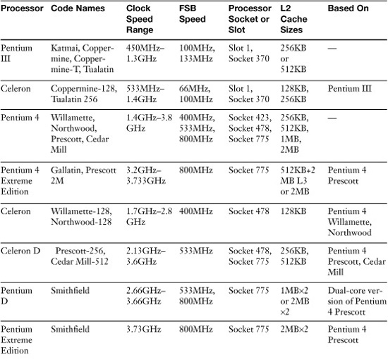
Table 3-5 provides a brief summary of Intel desktop processors produced from 1998 to mid 2008. For additional details, see Upgrading and Repairing PCs, 18th Edition.
Table 3-5 Intel Desktop Processors from Pentium III through Core 2 Extreme

AMD Processors
AMD processors contemporary with the Intel Pentium III and its successors include the following processor families as of mid 2008:
• Athlon
• Duron
• Athlon XP
• Sempron
• Athlon 64
• Athlon 64 FX
• Athlon 64 X2
• Phenom X4
The Athlon processor was the first (and last) AMD processor produced in a slot-based design. It uses Slot A, which physically resembled Slot 1 used by Intel Pentium II and Pentium III models, but was completely different in its pinout. Later versions of the Athlon switched to Socket A, a 462-pin socket, which was also used by the Duron, Athlon XP, and Socket A versions of the Sempron.
The Athlon XP replaced the Athlon, and featured higher clock speeds and larger L2 cache. The lower-performance counterpart of the Athlon and Athlon XP was the Duron, which featured a smaller L2 cache and slower FSB speed.
The Athlon XP design was used for the Socket A versions of the Sempron when AMD moved to 64-bit processing with the introduction of the Athlon 64, AMD’s first x64 64-bit desktop processor.
The Athlon 64 family initially used Socket 754, but because the memory controller is built into the processor, rather than into the North Bridge as on conventional processors, it was necessary to develop a new Socket 939 to support dual-channel memory.
The Athlon 64 FX is a faster performance–oriented version of the Athlon 64. Initial versions were based on the Opteron workstation and server processor, and thus used Socket 940. Later versions used Socket 939 and its successor, Socket AM2.
AMD’s first dual-core processor was the Athlon 64 X2, which uses a design that permits both processor cores to communicate directly with each other, rather than using the North Bridge (Memory Controller Hub) as in the Intel Pentium D. This enabled upgrades from Socket 939 Athlon 64 to the X2 version after performing a BIOS upgrade.
AMD’s economy version of the Athlon 64 is also called the Sempron, various versions of which have used Socket 754 and Socket 939.
AMD’s Phenom series is based on the AMD K10 processor architecture, and all Phenoms include multiple processor cores that are built as a single unit. The first two Phenom processors are the quad-core Phenom X4 and the three-core Phenom X3.
Because most AMD processor families have gone through many changes during their lifespans, specific models are sometimes referred to by their code names.
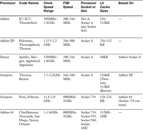
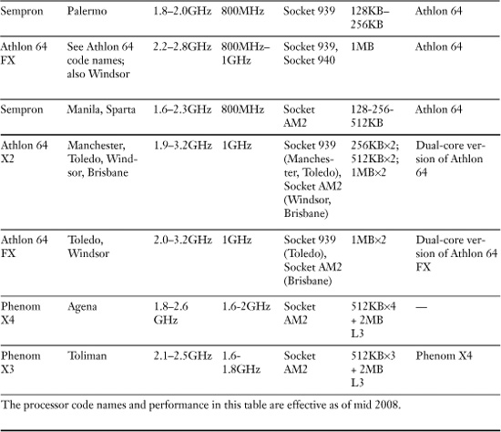
Table 3-6 provides a brief summary of AMD desktop processors produced over the last decade. For additional details, see Upgrading and Repairing PCs, 18th Edition.
Table 3-6 AMD Desktop Processors from Athlon through Phenom
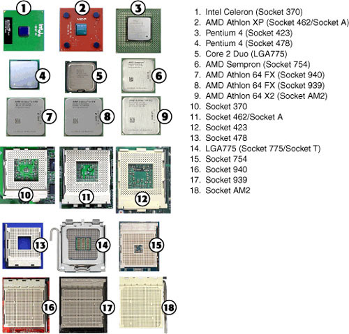
Processor Sockets and Packaging
Most processors listed in the previous sections use some form of the pin grid array (PGA) package, in which pins on the bottom of the processor plug into holes in the processor socket. The exceptions include slot-mounted processors (Slot 1 and Slot A) and the current LGA771 and LGA775 sockets, which uses a different type of processor package called the land grid array (LGA). LGA packaging uses gold pads on the bottom of the processor package to connect with raised leads in the processor socket.
Figure 3-21 compares processor packages and sockets to each other.
Figure 3-21 Intel and AMD processors and sockets.
CPU Technologies
Processor technologies in the following sections might be used by AMD only, by Intel only, or by both vendors. These technologies are used to help distinguish different processors from each other in terms of performance or features.
Hyperthreading (HT Technology)
Hyperthreading (HT Technology) is a technology developed by Intel for processing two execution threads within a single processor. Essentially, when HT Technology is enabled in the system BIOS and the processor is running a multithreaded application, the processor is emulating two physical processors. The Pentium 4 was the first desktop processor to support HT Technology, which Intel first developed for its Xeon workstation and server processor family.
Pentium 4 processors with processor numbers all support HT Technology, as do older models with 800MHz FSB and a clock speed of 3.06GHz or higher. HT Technology is not needed (and is therefore not present) in dual-core, three-core, and quad-core processors because each processor core is capable of handling separate execution threads in a multithreaded application.
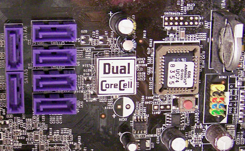
Dual-Core and Multi-Core
Two or more physical processors in a system enable it to perform much faster when multitasking or running multithreaded applications. However, systems with multiple processors are very expensive to produce and some operating systems cannot work with multiple processors. Dual core processors, which combine two processor cores into a single physical processor, provide virtually all of the benefits of two physical processors, and are lower in cost and work with any operating system that supports traditional single-core processors.
The first dual-core desktop processors were introduced by Intel (Pentium D) and AMD (Athlon 64 X2) in 2005. Athlon 64 X2’s processor cores communicate directly with each other, enabling systems running single-core Athlon 64 processors to swap processors after a simple BIOS upgrade. The Pentium D, on the other hand, required new chipsets to support it. The Core 2 Duo is Intel’s current dual-core processor, and, like the AMD Athlon 64 X2, the Core 2 Duo’s processor cores communicate directly with each other.
Both Intel and AMD have released processors that include more than two cores. Intel’s Core 2 Quad and some versions of the Core 2 Extreme contain four processor cores, while AMD’s Phenom x4 contains four processor cores and the Phenom x3 contains three.
Processor Throttling
Processors do not need to run at full speed when they have little, or no, work to perform. By slowing down—or throttling—the processor’s clock speed when the workload is light, the processor runs cooler, the system uses less energy, and—in the case of mobile systems—the computer enjoys a longer battery life. Throttling, sometimes referred to as thermal throttling, can also take place when a processor gets too hot for the computer’s cooling system to work properly.
Intel uses the terms SpeedStep or Enhanced SpeedStep for its throttling technologies. AMD uses the term Cool’n’Quiet for its throttling technology.
Microcode (MMX)
All Intel and AMD processors in current use include various types of microcode instructions for boosting multimedia performance. The first processor to include this type of microcode was the Pentium MMX, which included 57 new instructions (known as MMX) for working with multimedia. MMX was the first example of what is known as single instruction, multiple data (SIMD) capability.
Later Intel processors included enhanced versions of MMX known as SSE (MMX+70 additional instructions, introduced with the Pentium III), SSE2 (MMX+SSE+144 new instructions, introduced with the Pentium 4), SSE3 (MMX+SSE+SSE2+13 new instructions, introduced with the Pentium 4 Prescott), and, most recently, SSSE3 (MMX+SSE+SSE2+SSE3+32 new instructions, introduced with the Core 2 Duo).
AMD also provides multimedia-optimized microcode in its processors, starting with 3DNow! (introduced by the K6, which was roughly equivalent to the Pentium MMX). However, AMD’s version differs in details from Intel’s, offering 21 new instructions. The AMD Athlon introduced 3DNow! Enhanced (3DNow!+24 new instructions), while the Athlon XP introduced 3DNow! Professional (3DNow!+Enhanced+51). 3DNow! Professional is equivalent to Intel’s SSE. Starting with the Athlon 64 family, AMD now supports SSE2, and added SSE3 support to the Athlon 64 X2 and newer versions of the Athlon 64 family.
Overclocking
Overclocking refers to the practice of running a processor or other components, such as memory or the video card’s graphics processing unit (GPU) at speeds higher than normal. Overclocking methods used for processors include increasing the clock multiplier or running the front side bus (FSB) at faster speeds than normal. These changes are performed by altering the normal settings in the system BIOS setup for the processor’s configuration. Figure 3-22 is a typical BIOS processor configuration screen.
Figure 3-22 Preparing to overclock a system running an AMD Athlon 64×2 processor.

Most processors feature locked clock multipliers. That is, the clock multiplier frequency cannot be changed. In such cases, the only way to overclock the processor is to increase the front side bus speed, which is the speed at which the processor communicates with system memory. Increasing the FSB speed can lead to greater system instability than changing the clock multipliers.
Some processors from Intel and AMD feature unlocked clock multipliers, so that the user can choose the best method for overclocking the system. Overclocked processors and other components run hotter than normal, so techniques such as using additional cooling fans, replacing standard active heat sinks with models that feature greater cooling, and adjusting processor voltages are often used to help maintain system stability at faster speeds.
Cache
Cache memory, as mentioned previously, improves system performance by enabling the processor to reuse recently retrieved memory locations without needing to fetch them from main memory. Processors from AMD and Intel feature at least two levels of cache:
• Level 1 (L1) cache is built into the processor core. L1 cache is relatively small (8KB–64KB). When the processor needs to access memory it checks the contents of L1 cache first.
• Level 2 (L2) cache is also built into the processor. On older slot-mounted processors, L2 cache was external to the processor die, and ran at slower speeds than the processor. On socketed processors, L2 cache is built into the processor die. If the processor does not find the desired memory locations in L1 cache, it checks L2 cache next.
• Level 3 (L3) cache is found on a few very high-performance processors and is also built into the processor die. On systems with L3 cache, the processor checks L3 cache after checking L1 and L2 caches.
If cache memory does not contain the desired information, the processor retrieves the desired information from main memory, and stores copies of that information in its cache memory (L1 and L2, or L1, L2, and L3). Processors with larger L2 caches (or L2 and L3 caches) perform most tasks much more quickly than processors that have smaller L2 caches for two reasons. Cache memory is faster than main memory, and the processor checks cache memory for needed information before checking main memory.
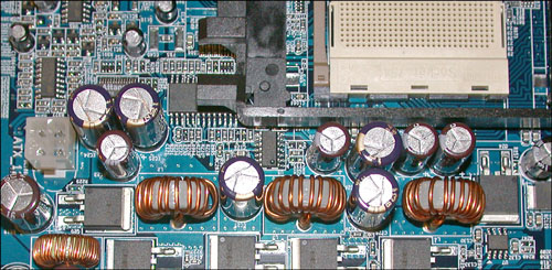
VRM
Starting with Socket 7 versions of the Intel Pentium, processors have not received their power directly from the power supply. Instead, a device called a voltage regulator module (VRM) has been used to reduce 5V or 12V DC power from the power supply to the appropriate power requested by the processor through its voltage identification (VID) logic.
Although some motherboards feature a removable VRM, most motherboards use a built-in VRM that is located next to the processor socket, as shown in Figure 3-23.
Figure 3-23 A portion of the VRM on an Athlon 64 motherboard.
Note
Be sure to determine the free space around a processor before ordering or installing a third-party active heat sink. Some motherboards have VRM components located so close to the processor that some heat sinks will not fit.
Speed (Real Versus Actual) Clock Speed Versus Performance
A common measurement of processor performance has been clock speed. However, clock speed can be misleading. For example, the Intel Core 2 Duo and AMD Athlon 64 x2 processors perform computing tasks much more quickly than the Pentium D, even though the Pentium D runs at a much higher clock speed.
To determine the actual performance of a processor, you should use benchmark tests such as Futuremark’s SYSmark, PCMark, and 3DMark.
32-bit Versus 64-bit
Processors developed before the AMD Athlon 64 were designed for 32-bit operating systems and applications. 32-bit software cannot access more than 4GB of RAM (in fact, 32-bit Windows programs can use only 3.25GB of RAM), which makes working with large data files difficult, as only a portion of a file larger than the maximum memory size can be loaded into memory at one time.
The Athlon 64 was the first desktop processor to support 64-bit extensions to the 32-bit x86 architecture. These 64-bit extensions, commonly known as x64, enable processors to use more than 4GB of RAM and run 64-bit operating systems, but maintain full compatibility with 32-bit operating systems and applications.
Late-model Pentium 4 processors from Intel also support x64, as do subsequent processors such as the Pentium 4 Extreme Edition, Pentium D, Pentium Extreme Edition, Core 2 Duo, Core 2 Quad, Core 2 Extreme, Phenom x4, and Phenom x2. Most processors made today support x64 operation.
Note
To learn more about a particular processor’s support for x64 operation, hardware virtualization, and other features, look up the processor specifications at the manufacturer’s website.
Choosing the Best Processor for the Job
If you are buying or building a new system, you have free rein in the choice of a processor to build the system around. This section describes important considerations.
Performance
If you need a system that can handle high-resolution graphics and video, and can perform heavy-duty number crunching, get the fastest dual-core or multi-core processor you can afford. However, if your requirements are less extreme, you can save money for your clients by opting for a processor from the same family with slower clock speed or less cache memory.
Thermal Issues
Many processor models are available in two or more versions that differ in their thermal requirements; that is, the type of active heat sink necessary to cool them and the amount of power (in watts) needed to operate them. In a mid-tower or full tower system, these considerations might be less important than in a micro-tower or small form factor system, or a system that might need to run as quietly as possible.
32-bit Versus 64-bit (x64) Compatibility
Unless you are trying to build the least-expensive system possible, you will find it difficult to find 32-bit only processors today. However, if you are repurposing existing systems, you might need to determine which systems include processors with support for 64-bit operation, and which support only 32-bit operation.
Other Processor Features
Processor features such as NX (no execute, which provides hardware-based protection against some types of viruses and malware) and hardware-based virtualization (which enables a single processor to be split into multiple virtual machines with little or no slowdown) are also important to consider in business environments. Check the specification sheets provided by processor vendors to determine the exact features supported by a particular processor.
Tip
To help determine detailed information for current and late-model installed Intel processors (Pentium 4, Celerons based on the Pentium 4 and newer), use the Intel Processor Identification Utility available from the Intel website (www.intel.com).
For older Intel processors, use the Intel Processor Frequency ID Utility, also available from the Intel website.
To help determine detailed information for installed AMD processors, download and install CPUInfo from the AMD website (www.amd.com).
Installing Processors
Processors are one of the most expensive components found in any computer. Because a processor can fail, or more likely, might need to be replaced with a faster model, knowing how to install and remove processors is important. On the A+ Certification exams, you should be prepared to answer questions related to the safe removal and replacement of Pentium III-class or newer processors.
The methods used for CPU removal vary according to two factors: the processor type and the socket/slot type.
As you saw in Tables 3-5 and 3-6, most recent processors are socketed. Before the development of the ZIF socket, the processor was held in place by tension on the chip’s legs, pins, or leads. Thus, to remove these chips, you must pull the chip out of the socket. Because the chip’s legs, pins, or leads are fragile, special tools are strongly recommended for removing chips that are not mounted in ZIF sockets. Before removing and installing any CPU or other internal component, be sure to review and follow the ESD precautions discussed in Chapter 17.
Removing the Heat Sink
ZIF sockets are used on almost all desktop systems using Pentium III-class or newer socketed processors (except for processors using LGA 771 or 775). They allow easy installation and removal of the processor.
What makes ZIF sockets easy to work with? They have a lever that, when released, loosens a clamp that holds the processor in place.
If the processor has a removable heat sink, fan, or thermal duct that is attached to the motherboard, you must remove these components before you can remove the processor.
Heat sinks used on Socket 370 and Socket A processors have a spring-loaded clip on one side and a fixed lug on the other side. To release this clip, press down on it using a screwdriver, as shown in Figure 3-24.
Figure 3-24 Releasing the spring clip on a Socket A processor’s heat sink.

Most newer processors use heat sinks that are attached to a frame around the processor or are mounted through the motherboard. To release these heat sinks, you might need to flip up a lever on one side of the heat sink or release the locking pins. Figure 3-25 illustrates a typical installation on an Athlon 64 processor, and Figure 3-26 illustrates the components of a typical heat sink for LGA 775 processors.
Figure 3-25 Typical heat sink assembly on Athlon 64 processor.

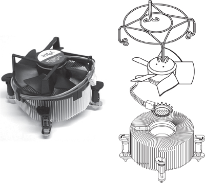
Figure 3-26 Stock heat sink assembly for Intel Core 2 Duo LGA 775 processor.
BTX systems use a horizontally mounted thermal module that is equipped with a fan. The thermal module also helps cool other components such as the motherboard chipset and memory. Figure 3-27 illustrates a typical thermal module installed on a motherboard. Note that the front of the thermal module extends below the edge of the motherboard to provide cooling for both top and bottom.
Figure 3-27 Thermal module placement on a typical BTX motherboard. Figure courtesy of Formfactors.org.

To remove a thermal module from a BTX motherboard, follow these steps:
Step 1. Remove the screws that attach the module to the retention bracket on the underside of the motherboard.
Step 2. Disconnect the thermal module’s fan power lead.
Step 3. Lift the thermal module off the processor.
Removing the Processor
After removing the heat sink, follow these instructions to complete the processor removal process.
Step 1. Disconnect the active heat sink (if included) from its power source and lift the assembly away.
Step 2. Push the lever on the ZIF socket slightly to the outside of the socket to release it.
Step 3. Lift the end of the lever until it is vertical (see Figure 3-28). This releases the clamping mechanism on the processor’s pins.
Figure 3-28 After the heat sink fan is disconnected from power (left) to reveal the processor (center), the lever on the ZIF socket (right) can be lifted to release the processor.
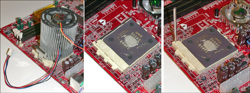
Step 4. Grasp the processor on opposite sides, making sure not to touch the pins, and remove it from the socket. Put it into antistatic packaging.
The process of removing an LGA 775 processor is a bit different:
Step 1. Disconnect the active heat sink (if included) from its power source and lift the assembly away.
Step 2. Lift the locking lever to release the load plate, which holds the processor in place.
Step 3. Carefully lift the processor away and place in into antistatic packaging.
Installing a New Processor
Before installing a new processor, verify that the processor you plan to install is supported by the motherboard. Even though a particular combination of processor and motherboard might use the same socket, issues such as BIOS, voltage, or chipset considerations can prevent some processors from working on particular motherboards. You can destroy a processor or motherboard if you install a processor not suitable for a particular motherboard.
After verifying compatibility by checking the system or processor manual (and installing any BIOS updates required for processor compatibility), check a PGA-type processor for bent pins, and the socket of an LGA775 processor for bent leads. Correct these problems before continuing.
To insert a PGA-type CPU into a ZIF socket, find the corner of the chip that is marked as pin 1 (usually with a dot or triangle). The underside of some chips might be marked with a line pointing toward pin 1. Then follow these steps:
Step 1. Line up the pin 1 corner with the corner of the socket also indicated as pin 1 (look for an arrow or other marking on the motherboard). If you put the chip in with pin 1 aligned with the wrong corner and apply the power, you will destroy the chip.
Step 2. Make sure the lever on the ZIF socket is vertical; insert the CPU into the socket and verify that the pins are fitting into the correct socket holes.
Step 3. Lower the lever to the horizontal position and snap it into place to secure the CPU.
Step 4. Before attaching the heat sink or fan, determine if the heat sink has a thermal pad (also called a phase-change pad) or if you need to apply thermal compound to the processor core (refer to Figure 3-27). Remove the protective tape from the thermal pad or apply thermal compound as needed. Attach the heat sink or fan. You must use some type of thermal compound between the processor and the bottom of the heat sink.
Step 5. Attach the heat sink to the processor as directed by the processor vendor (for heat sinks supplied with the processor) or heat sink vendor (for aftermarket heat sinks). In some cases, you might need to attach mounting hardware to the motherboard before you can attach the heat sink.
Step 6. If you are installing an active heat sink (a heat sink with a fan), plug the fan into the appropriate connector on the motherboard.
To insert an LGA775 processor, locate the notches on each side of the processor. These correspond with key tabs in the processor socket. Then follow these steps:
Step 1. Make sure the load plate assembly is completely open. It has a plastic cover that can be removed at the end of Step 5.
Step 2. Line up the notches in the processor with the key tabs in the processor socket. This assures that the processor’s Pin 1 is properly aligned with the socket.
Step 3. Lower the processor into place, making sure the metal heat spreader plate faces up and the gold pads face down. Do not drop the processor, as the lands in the processor socket could be damaged.
Step 4. Push down the load plate and close the load plate assembly cam lever.
Step 5. Lock the lever in place on the side of the socket. Remove the plastic cover and save it for future use.
Step 6. Before attaching the heat sink or fan, determine if the heat sink has a thermal pad (also called a phase-change pad) or if you need to apply thermal compound to the processor core (refer to Figure 3-27). Remove the protective tape from the thermal pad or apply thermal compound as needed. Attach the heat sink or fan. You must use some type of thermal compound between the processor and the bottom of the heat sink.
Step 7. Attach the heat sink to the processor as directed by the processor vendor (for heat sinks supplied with the processor) or heat sink vendor (for aftermarket heat sinks). In some cases, you might need to attach mounting hardware to the motherboard before you can attach the heat sink.
Step 8. If you are installing an active heat sink (a heat sink with a fan), plug the fan into the appropriate connector on the motherboard.
Slot-Type CPU (early Pentium III, early AMD Athlon, and Others)
You won’t see many slot-type CPUs anymore, but if you need to install one on a motherboard, make sure the motherboard has a retention mechanism attached. If the motherboard doesn’t have one, you will need to remove the motherboard from the case to attach a retention mechanism if it is not already attached.
To remove a slot-type CPU, follow these steps:
Step 1. Push down on the retainers at each end of the CPU to release the CPU from the retention mechanism.
Step 2. Disconnect the power lead to the CPU fan (if present).
Step 3. Remove the CPU and fan/heat sink from the retention mechanism. The CPU slides straight up from the slot.
To attach a slot-type CPU, follow these steps
Step 1. Attach the CPU retention mechanism to the motherboard. Leave the foam backing on the bottom of the motherboard while pushing the supports into place. Lift up the motherboard and secure the retention mechanism with the screws supplied.
Some motherboards are shipped with the retention mechanism already installed, so this step might not apply to you. If the retention mechanism is folded against the motherboard, unfold it so the supports stand straight up.
Step 2. Attach the fan and heat sink to the CPU if it is not already attached; some CPUs have a factory-attached heat sink/fan, whereas others require you to add it in the field.
Step 3. Match the pinouts on the bottom of the CPU to the motherboard’s slot; note that the slot has two sides of unequal length, making it easy to match the slot with the CPU.
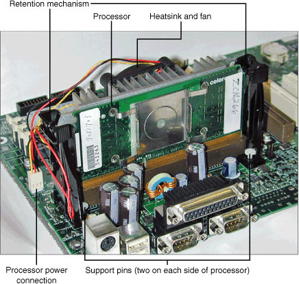
Step 4. Insert the CPU into the retention mechanism; push down until the retaining clips lock the CPU into place. Figure 3-29 shows the CPU in place.
Figure 3-29 A Slot 1–based Celeron CPU after installation. The heat sink and fan are attached to the rear of the CPU.
Step 5. Connect the power lead from the fan (if present) to the motherboard or drive power connector as directed.
Troubleshooting Processors
Keeping the processor running reliably is vital to correct system operation. This section focuses on some common problems and solutions.
System Runs Slower Than Rated Speed
A system running slower than its rated speed might do so because of processor throttling due to overheating, less than optimal settings in the Windows Power Management utility in Control Panel, or because of incorrect BIOS timing.
Overheating of the Processor or System
A system that overheats will stop operating, and with some older processors serious damage can result. Most processors today are fitted with active heat sinks that contain a fan. If the fan stops working, the process will overheat.
Fan failures can be caused by dirt in the fan, worn-out bearings, or a bad connection to the motherboard or drive-cable power. In most cases, it’s better to replace the heat sink fan than to try to clean it. If you must clean it, follow these steps:
Step 1. Remove the heat sink from the CPU.
Step 2. Place it on a surface covered with old newspapers or waste paper.
Step 3. Blow it out with compressed air.
Before reattaching the heat sink, clean the old thermal material from the processor and the heat sink and reapply a small amount of thermal material to the top center of the processor cap. For specific thermal material installation recommendations for a particular processor, check the processor manufacturer’s website.
If you opt for a replacement fan, improve reliability and life by specifying a ball-bearing fan rather than the typical (and cheap) sleeve-bearing units. Overheating can also be caused by a dirty power supply or case fan, or by missing slot covers. Clean or replace the fans, and replace the slot covers. Don’t overlook cleaning out the inside of the case, because a dirty case interior will eventually clog other components due to the system’s airflow.
The hardware monitor feature in the system BIOS can warn of overheating or fan failure. This is most effective if the motherboard or system vendor’s monitoring software is also installed so you can be warned of problems while Windows is running.
Underclocked System
Some systems revert to a “fail-safe” setting in which the CPU frequency and/or clock multiplier default to low-speed settings if the system fails to boot properly or is shut off before starting. Check the system speed reported on the System properties sheet in Windows XP or the CPU frequency/multiplier values in the BIOS. If these values are incorrect, set the CPU frequency and multiplier values according to the processor manufacturer’s guidelines. See Chapter 4 for details.
If the system is configured to automatically detect the correct values for CPU frequency and clock multiplier but will not report the correct speed, the system might need a BIOS upgrade to properly support the processor, or you might be using a remarked processor (one that has had its original model number and technical information altered to make it appear as if it’s a faster processor).
Other Causes for Overheating
Overheating issues directly related to the processor can include fan failure and incorrect heat sink for the processor type.
Fan Failure
Heat sink fans don’t have to stop turning to fail; if they turn more slowly than they are specified to run, they can cause processor overheating.
Incorrect Heat Sink for Processor Type/Speed
If the processor overheats and the heat sink is properly attached and the fan is running, make sure the heat sink is designed for the processor type and speed in use. Heat sinks made for lower speed processors might not provide adequate cooling for faster processors, which often run at higher temperatures.
Use the heat sink provided by the processor vendor, or, if you are using a separately purchased heat sink, make sure the heat sink is designed for the processor type and speed in use.
Processor Failure
If the processor is not locked into place, you will not be able to attach the heat sink. Never run the system if the processor is not properly installed, including heat sink installation.
Installing Adapter Cards
Although most desktop systems are equipped with a wide variety of I/O ports and integrated adapters, it is still often necessary to install adapter cards to enable the system to perform specialized tasks or to achieve higher performance. The following sections show you how to perform typical installations.
General Installation
Before installing an adapter card, you should determine the following:
• Does the adapter card perform the same task as an integrated adapter?— For example, if you are installing a display adapter (also called a graphics card or video card), does the system already have an integrated adapter? If you are installing a sound card, does the system already have a sound card? Depending upon the type of card you are installing, it might be necessary to disable the comparable onboard feature first to avoid hardware resource conflicts.
• What type(s) of expansion slots are available for expansion cards?— A typical system today might have two or three different types of expansion slots, such as PCI Express x16, PCI Express x1 and PCI, or PCI and AGP, as shown in Figure 3-30. PCI Express x1 and PCI slots can be used for a variety of adapter cards, while PCI Express and AGP slots are designed for display adapters. The adapter card you select must fit into an available slot.
Figure 3-30 AGP, PCI, PCI Express x1 and x16 slots on typical motherboards. Arrow indicates rear of motherboard.

• When PCI and PCI Express x1 slots are available, which slot should be used?— PCI Express x1 slots provide higher performance than PCI slots, and should be used whenever possible.
To learn how to change BIOS configuration settings to disable onboard ports, see Chapter 4.
The general process of installing an adapter card works like this:
Step 1. Shut down the system.
Step 2. Disconnect it from AC power, either by unplugging the system or by turning off the power supply with its own on/off switch.
Step 3. Remove the system cover. Depending upon the motherboard design and case design, the exact method varies:
• If the case has a one-piece design, remove the entire case.
• If the case is a tower design with removable side panels, remove the left side panel (as seen from the front) to install cards into an ATX system. Remove the right side panel to install cards into a BTX system.
Step 4. Locate the expansion slot you want to use. If the slot has a header cable installed in the slot cover, you will need to move the header cable to a different slot. Figure 3-31 illustrates a typical system that has some available slots.
Figure 3-31 A typical system has some available slots and some that are not available for various reasons.
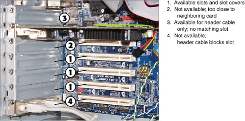
Step 5. Remove the slot cover corresponding to the slot you want to use for the adapter card. Most slot covers are held in place by set screws that fasten the slot cover to the rear of the case, as shown in Figure 3-31. However, some systems use different methods.
Tip
If you are unable to remove the slot cover after removing the set screw, loosen the set screw on the adjacent slot cover. Sometimes the screw head overlaps the adjacent slot cover.
Step 6. Remove the card from its antistatic packaging. Hold the card by the bracket, not by the circuit board, chips, or card connector. Figure 3-32 illustrates a typical card and where to hold it safely.
Figure 3-32 A typical adapter card. Callouts indicate where it is safe and not safe to hold the card.
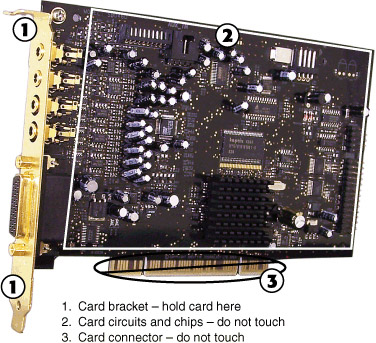
![]()
Step 7. Insert the card into the expansion slot, lining up the connector on the bottom.
Step 8. Push the card connector firmly into the slot.
Step 9. Secure the card bracket; on most systems, you will secure the card bracket by replacing the set screw. See Figure 3-33.
Figure 3-33 An improperly installed card compared with a properly installed card.

![]()
Step 10. Connect any cables required for the card.
Step 11. Reconnect AC power and restart the system.
Step 12. When the system restarts, provide drivers as prompted.
The following sections discuss some special installation considerations that apply to some types of adapter cards.
Display Adapters
Before installing a display adapter in a working system, you should open Device Manager and uninstall the current display adapter. To learn more about using Device Manager, see Chapter 13.
Display adapters are available for PCI Express x16, AGP, and PCI expansion slots. Display adapters in PCI form factor are intended for use in systems that don’t have PCI Express or AGP slots, or to provide support for additional displays on systems that already have PCI Express or AGP cards installed.
When you install a card into an AGP slot, make sure the card locking mechanism on the front of the slot is open before you install the card. Locking mechanisms sometimes use a lever that is moved to one side, flips up and down, or has a locking tab that is pulled to one side.
After installing the display adapter, install the drivers provided by the graphics card vendor. If possible, use updated drivers downloaded from the vendor’s website rather than the ones provided on CD.
When connecting the monitor(s) to the display adapter, keep in mind that CRT and some LCD monitors use the 15-pin VGA connector, while many LCD monitors use the larger DVI connector. You can use an adapter to enable a DVI-I connector on a display adapter to connect to a monitor that uses the VGA connector. To learn more about display adapters and graphics cards, see Chapter 8.
Sound Cards
After installing a sound card, you must connect 1/4-inch mini-jack cables from speakers and the microphone to the sound card. Most sound cards use the same PC99 color-coding standards for audio hardware that are used by onboard audio solutions, as described in Table 3-7.
Table 3-7 PC99 Color Coding for Audio Jacks
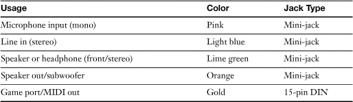
![]()
After installing the sound card, you are prompted to install drivers when you restart the system. The driver set might also include a customized mixer program that is used to select speaker types, speaker arrangement (stereo, 5.1, and so on), and provides speaker testing and diagnostics. Be sure to test the speakers to assure they are plugged into the correct jack(s) and are working properly.
Video Capture Cards
Video capture cards are used to capture video from analog or digital video sources. Video capture card types include
• IEEE 1394 (FireWire) cards— These capture video from DV camcorders and can also be used for other types of 1394 devices, such as hard disks and scanners. An onboard IEEE 1394 port can also be used for video capture.
• Analog video capture cards— These capture video from analog sources, such as cable or broadcast TV, composite video, or S-video. Many of these cards also include TV tuners. Examples include the Hauppauge WinTV PVR series and the ATI Theater Pro series.
• Digital video capture card— These capture digital video from HDMI sources, such as HDTV.
• The ATI All-in-Wonder series— These cards incorporate accelerated 3D video display output to monitors, video capture, and TV tuner support.
After installing any type of video capture card, you need to install the drivers provided with the card, connect the card to video sources, and, in the case of cards with onboard TV tuners, set up the TV tuner feature.
Troubleshooting Adapter Cards
Adapter card problems can be detected in the following ways:
• A device connected to the adapter card doesn’t work.
• The adapter card listing in Device Manager indicates a problem.
To solve these problems, see the following sections.
Device Connected to Adapter Card Doesn’t Work
If a device connected to an adapter card doesn’t work, it could indicate a variety of issues. After verifying that the device works on another system, check the following:
• Check Device Manager and make sure the adapter card is listed as working. Windows XP uses the yellow ! symbol to indicate devices that are not working, and the red X mark to indicate devices that have been disabled. In some cases, an adapter card will work after you install a driver upgrade. To learn more about driver and firmware upgrades, see “Performing Driver and Firmware Upgrades,” in this chapter. To learn more about using Device Manager, see Chapter 13.
• Check the system BIOS setup to ensure that any onboard devices that might interfere with the adapter card’s operation have been disabled.
• Make sure the adapter card is properly secured in the expansion slot. Refer to Figure 3-33.
• If the adapter card requires additional power, make sure an appropriate power cable is connected from the power supply to the card. Some IEEE-1394 and display adapter cards require additional power to operate properly.
Performing Driver and Firmware Upgrades
A device is only as good as the software that makes it work. Device drivers are found in two forms:
• Driver files
• Firmware
The drivers for most devices installed in Windows can be updated through the Update Driver wizard found in the properties sheet for the device in Device Manager. The wizard can locate updated drivers on the Internet or can be directed to install drivers from a location you provide, such as drivers on a floppy disk, CD, or a particular folder on a hard disk.
To learn more about using Device Manager, see Chapter 13.
Firmware, which is software stored on a flash memory chip, can also be upgraded, although most adapter cards don’t use upgradeable firmware. If a firmware upgrade is available from the adapter card vendor, follow the vendor’s instructions for installing the upgrade.
Some upgrades are installed by creating a special boot disk from the downloaded file provided by the vendor, while others are installed from within Windows. Regardless of how firmware is upgraded, it’s very important to keep in mind that the upgrade process can take two or three minutes and must not be interrupted. If the firmware process is interrupted, the card will no longer function, and it must be repaired or replaced.
Exam Preparation Tasks
Review All the Key Topics
Review the most important topics in the chapter, noted with the key topics icon in the outer margin of the page. Table 3-8 lists a reference of these key topics and the page numbers on which each is found.
Table 3-8 Key Topics for Chapter 3
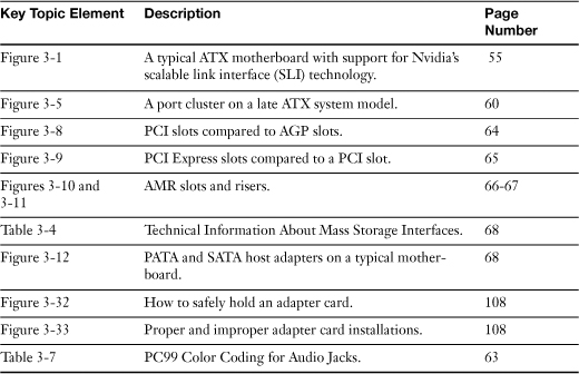
Complete the Tables and Lists from Memory
Print a copy of Appendix B, “Memory Tables,” (found on the CD), or at least the section for this chapter, and complete the tables and lists from memory. Appendix C, “Memory Tables Answer Key,” also on the CD, includes completed tables and lists to check your work.
Definitions of Key Terms
Define the following key terms from this chapter, and check your answers in the glossary.
CPU,
PCI,
AGP,
PATA,
SATA,
Troubleshooting Scenario
You have recently purchased a 500GB storage device. You plug it in to your system and nothing happens. What could be the cause of the problem, and how would you correct this?
Refer to Appendix A, “Answers to the ‘Do I Know This Already?’ Quizzes and Troubleshooting Scenarios,” for the answer.