
Chapter 4. BIOS
This chapter covers a portion of the CompTIA A+ 220-701 objective 1.2 and CompTIA A+ 220-702 objective 1.2.
The basic input/output system (BIOS) is an essential component of the motherboard. This boot firmware, also known as System BIOS, is the first code run by a computer when it is booted. It prepares the machine by testing it during boot-up and paves the way for the operating system to start. It tests and initializes components such as the processor, RAM, video card, magnetic disks, and optical disks. If any errors occur, the BIOS will report them as part of the testing stage, known as the power-on self test (POST). The BIOS resides on a ROM chip and stores a setup program that you can access when the computer first boots up. From this program, a user can change settings in the BIOS and upgrade the BIOS as well. Within this chapter you will find out about how the BIOS, CMOS, and batteries on the motherboard interact, and will learn how to configure and upgrade the BIOS.
“Do I Know This Already?” Quiz
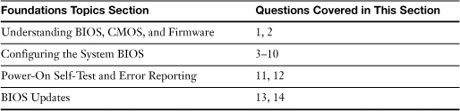
The “Do I Know This Already?” quiz allows you to assess whether you should read this entire chapter or simply jump to the “Exam Preparation Tasks” section for review. If you are in doubt, read the entire chapter. Table 4-1 outlines the major headings in this chapter and the corresponding “Do I Know This Already?” quiz questions. You can find the answers in Appendix A, “Answers to the ‘Do I Know This Already?’ Quizzes and Troubleshooting Scenarios.”
Table 4-1 “Do I Know This Already?” Foundation Topics Section-to-Question Mapping
1. What is the CMOS memory used for?
a. Keeping the time
b. To store BIOS settings
c. To boot the computer
d. None of these options is correct
2. What happens when the CMOS battery fails?
a. All the CMOS configuration information is lost
b. The computer won’t boot
c. The computer is destroyed
d. The motherboard is dead
3. To make changes to the default settings in the BIOS, what must you do at startup?
a. Press the F2 key
b. Press Enter
c. Press the F8 key
d. Hold down the shift key
4. What BIOS settings will allow you to automatically configure your system? (Choose all that apply.)
a. BIOS Defaults
b. Setup Defaults
c. Turbo
d. Function
5. Which of the following will not work when configuring or viewing BIOS settings?
a. Esc Key
b. Enter Key
c. The + key
d. The mouse
6. Of the following system information, which can be viewed in the BIOS? (Choose all that apply.)
a. Installed Memory (RAM)
b. BIOS Information
c. Processor Type
d. Processor Speed
e. L2 cache memory
f. Feature settings
7. What features can be found in the advanced BIOS settings? (Choose two.)
a. Enable quick boot
b. Change the clock
c. View information
d. Enable boot sector protection
8. In today’s most recent systems, what common feature is used to help prevent excessive heat from damaging you computer?
a. Task Manager
b. System Monitor
c. Hardware Monitor
d. Drive Lock
9. Which of the following security features are included in most of the currently used BIOSs programs?
a. BIOS Password
b. Power on password
c. Chassis Intrusion
d. Boot sector protection
e. All these options are correct
10. What option would you use if you are in the BIOS of your computer and you want to exit without making any changes? (Choose all that apply.)
a. Save Configuration
b. Discard Changes
c. Hit the ESC key
d. Press F8 to return to desktop
11. When you start your computer, it performs an important test. What is this test known as?
a. CPU Processing
b. POST
c. A CMOS test
d. Hard drive test
12. What are BIOS beep codes used for? (Choose two.)
a. A fatal error
b. A system message
c. A serious error
d. A warning message
13. If you are installing a new drive in your computer and it is not recognized, what can you do to fix the problem?
a. Update the BIOS
b. Call the company of the new drive
c. Search for problems on the Internet
d. Refer to the information that came with the drive
14. What is the process called when upgrading the BIOS?
a. Putting a new BIOS chip on the motherboard
b. Removing the CMOS battery
c. Flashing the BIOS
d. Windows Update
Foundation Topics
Understanding BIOS, CMOS, and Firmware
You know what the CPU does—it does the “thinking” for the computer. But, how does the CPU “know” what kinds of drives are connected to the computer? What tells the CPU when the memory is ready to be read or written to? What turns on the USB ports or turns them off? The answer to all these questions is the BIOS. Next to the CPU, the BIOS (basic input output system) chip is the most important chip found on the motherboard. Figure 4-1 illustrates the location of the BIOS chip on some typical systems.
Figure 4-1 BIOS chips and CMOS batteries on typical motherboards.

![]()
The BIOS is a complex piece of firmware (“software on a chip”) that provides support for the following devices and features of your system:
• Selection and configuration of storage devices connected to the motherboard’s host adapters, such as hard drives, floppy drives, and CD-ROM drives
• Configuration of main and cache memory
• Configuration of built-in ports, such as PATA and SATA hard disk, floppy disk, serial, parallel, PS/2 mouse, USB, and IEEE-1394 ports
• Configuration of integrated (built into the motherboard chipset) audio, network, and graphics features when present
• Selection and configuration of special motherboard features, such as memory error correction, antivirus protection, and fast memory access
• Support for different CPU types, speeds, and special features
• Support for advanced operating systems, including networks and plug-and-play versions of Windows
• Power management
• Hardware monitoring (processor temperature, voltage levels, and fan performance)
Without the BIOS, your computer would be a collection of metal and plastic parts that couldn’t interact with one another or do much of anything but gather dust.
The BIOS also performs two other important tasks:
• It runs the power-on self test (POST) when the system is started.
• It establishes a list of locations that can be used by an operating system to boot the computer (hard disk, CD or DVD drive, USB drive, floppy drive, network) and turns over control of the system by using the Bootstrap loader after completing its startup tasks.
The BIOS doesn’t do its job alone. It works with two other important components:
• CMOS memory
• Motherboard battery (also called the CMOS battery; refer to Figures 4-1 and 4-2)
Figure 4-2 The CR2032 lithium watch battery (center) is the most common battery used to maintain CMOS settings in recent systems, but other batteries such as the Dallas Semiconductor DS12887A clock/battery chip (left) and the AA-size 3.6 volt (V) Eternacell (right) have also been used in older systems.

![]()
In the following sections, you’ll learn more about how these components work together to control system startup and onboard hardware.
Note
For much more information about BIOS functions, beep codes, and upgrades, see the BIOS chapter in the most recent edition of Scott Mueller’s Upgrading and Repairing PCs.
Standard settings are configured by the motherboard or system vendor, but can be overridden by the user to enable the system to work with different types of hardware or to provide higher performance. CMOS memory, also referred to as non-volatile memory, is used to store BIOS settings. CMOS memory should not be confused with system memory (RAM); CMOS memory is built into the motherboard and cannot be removed by the user.
The contents of CMOS memory are retained as long as a constant flow of DC current from a battery on the motherboard is provided. Some typical CMOS batteries are shown in Figure 4-2.
When the battery starts to fail, the clock will start to lose time. Complete battery failure causes the loss of all CMOS configuration information (such as drive types, settings for onboard ports, CPU and memory speeds, and much more). When this takes place, the system cannot be used until you install a new battery and re-enter all CMOS configuration information by using the CMOS configuration program.
Because the battery that maintains settings can fail at any time, and viruses and power surges can also affect the CMOS configuration, you should record important information before it is lost.
Tip
At one time, many system BIOS programs supported printing BIOS screens to a printer connected to the parallel port. Those days are gone (in fact, so are parallel printers, as well as printer ports!). However, you can still document BIOS screens the easy way: use a digital camera set for macro (close-up) mode. That’s the method I used to record BIOS screens for this chapter, and it works very well.
Configuring the System BIOS
The system BIOS has default settings provided by the system or motherboard maker, but as a system is built up with storage devices, memory modules, adapter cards, and other components, it is usually necessary to alter the standard settings.
To perform this task, the system assembler must use the BIOS setup program to make changes and save them to the CMOS. Originally, the BIOS setup program was run from a bootable floppy disk, but for many years most system BIOS chips have included the setup program.
Accessing the BIOS Setup Program
On most systems built since the late 1980s, the BIOS configuration program is stored in the BIOS chip itself. Just press the key or key combination displayed onscreen (or described in the manual) to get started.
Although these keystrokes vary from system to system, the most popular keys on current systems include the escape (Esc) key, the Delete (Del) key, the F1 key, the F2 key, the F10 key, and various combinations of Ctrl+Alt+ another specified key.
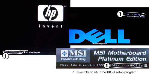
Most recent systems display the key(s) necessary to start the BIOS setup program at startup, as in Figure 4-3. However, if you don’t know which key to press to start your computer’s BIOS setup program, check the system or motherboard manual for the correct key(s).
Figure 4-3 The splash screens used by many recent systems display the keystrokes needed to start the BIOS setup program.
Note
Because the settings you make in the BIOS setup program are stored in the non-volatile CMOS, the settings are often called CMOS settings or BIOS settings.
In the following sections, we will review the typical setup process, looking at each screen of a typical desktop system with an Athlon 64 x2 processor.
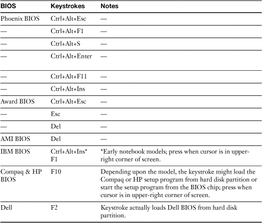
Table 4-2 Common Keystrokes Used to Start the BIOS Setup Program
![]()
Caution
BIOS programs vary widely, but the screens used in the following sections are representative of the options available on typical recent systems; your system might have similar options, but place the settings on different screens than those shown here. Laptop and corporate desktop systems generally offer fewer options than those shown here.
Be sure to consult the manual that came with your computer or motherboard before toying with the settings you find here. Monkeying with the settings can improve performance, but it can also wreak havoc on an otherwise healthy PC if you don’t know what you’re doing. Be warned!
BIOS Settings Overview
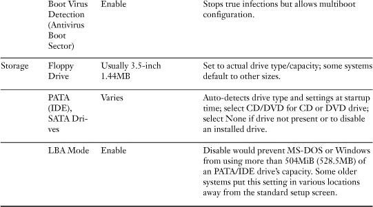
Table 4-3 provides a detailed discussion of the most important CMOS/BIOS settings. Use this table as a quick reference to the settings you need to make or verify in any system. Examples of these and other settings are provided in the following sections.
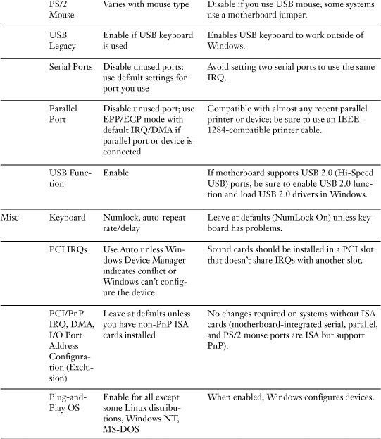
Table 4-3 Major CMOS/BIOS Settings


Automatic Configuration of BIOS/CMOS Settings
Let’s be frank—after reading Table 4-3, you might be wondering, “Isn’t there an easier way to configure the BIOS?” Well, actually there is, in a way.
Many BIOS versions enable you to automatically configure your system with a choice of these options from the main menu:
• BIOS defaults (also referred to as Original/Fail-Safe on some systems)
• Setup defaults (also referred to as Optimal on some systems)
• Turbo
These options primarily deal with performance configuration settings in the BIOS, such as memory timings, memory cache, and the like. The settings used by each BIOS setup option are customized by the motherboard or system manufacturer.
Use BIOS defaults to troubleshoot the system because these settings are very conservative in memory timings and other options. Normally, the Setup defaults provide better performance. Turbo, if present, speeds the memory refresh rate used by the system. As you view the setup screens in this chapter, you’ll note these options are listed.
Caution
If you use automatic setup after you make manual changes, all your manual changes will be overridden. Use one of these settings first (try Turbo or Setup Defaults) and then make any other changes you want.
With many recent systems, you can select Optimal or Setup defaults, save your changes, and exit, and the system will work acceptably. However, you might want more control over your system. In that case, look at the following screens and make the necessary changes.
Selecting Options
On typical systems, you set numerical settings, such as date and time, by scrolling through allowable values with keys such as + and − or page up/page down. However, you select settings with a limited range of options, such as enable/disable or choices from a menu, by pressing the Enter key on the keyboard and choosing the option desired from the available choices.
Main Menu
When you start the BIOS configuration program for your system, you might see a menu similar to the CMOS Setup Utility menu shown in Figure 4-4. From this menu, you can go to any menu, select default settings, save changes, or exit the CMOS setup menu.
Figure 4-4 A typical CMOS Setup utility main menu.

![]()
Tip
If you need to quickly find a particular BIOS setting and you don’t have the manual for the system or the motherboard, visit the system or motherboard vendor’s website and download the manual. In most cases, especially with a motherboard-specific manual, the BIOS screens are illustrated. Most vendors provide the manuals in Adobe Reader (PDF) format.
Standard Features/Settings
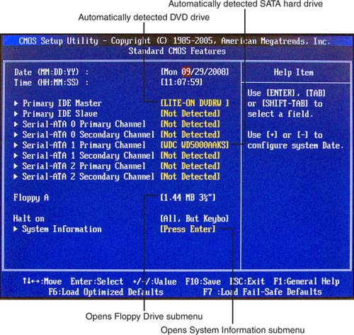
The Standard Features/Settings menu (Figure 4-5 shows an example) is typically used to configure the system’s date and time as well as drives connected to PATA (ATA/IDE), SATA, and floppy drive interfaces on the motherboard.
Figure 4-5 A typical CMOS Standard Features/Settings menu.
Note
Some BIOS setup programs open this menu and provide access to other menus with a top-level menu bar.
PATA and SATA BIOS Configuration
Most recent systems automatically detect the drive connected to each PATA and SATA host adapter, as shown earlier in Figure 4-5. However, some systems might use manual entry of the correct settings instead. These are usually listed on the drive’s faceplate or in the instruction manual. See Chapter 12, “Storage Devices,” for details.
Caution
Although some users recommend that you configure the settings for hard drives to user-defined, which will list the exact settings for each hard drive, this can cause a major problem in case your BIOS settings are lost due to a virus, battery failure, or other causes. If you are not an experienced user, I highly recommend you let your computer do the work by using the Auto feature.
Floppy Drive BIOS Configuration
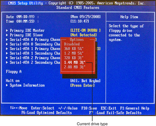
On systems that have an onboard floppy drive, the floppy drive must be selected manually if a different type of floppy drive is installed, or if the floppy drive is not present (see Figure 4-6).
Figure 4-6 Viewing available floppy disk drive types.
Tip
If your system supports an internal floppy drive, but you don’t use the drive, you might be able to disable the floppy controller. In such cases, you will no longer need to select Disabled from the menu shown in Figure 4-6.
System Information
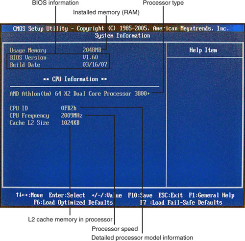
Some systems display system information such as processor type, clock speed, cache memory size, installed memory (RAM), and BIOS information on the standard menu or a submenu, as shown in Figure 4-7. Use this information to help determine if a system needs a processor, memory, or BIOS update.
Figure 4-7 Viewing system information.
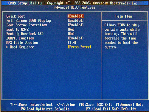
Advanced BIOS Settings/Features
The Advanced BIOS Settings/Features menu typically includes settings that control how the system boots, as shown in Figure 4-8. Enabling Quick Boot skips memory and drive tests to enable faster startup. Enabling Boot Sector Protection provides some protection against boot sector computer viruses. Enabling Boot Up Num-Lock LED turns on the keyboard’s Num Lock option.
Figure 4-8 A typical Advanced BIOS Features menu.
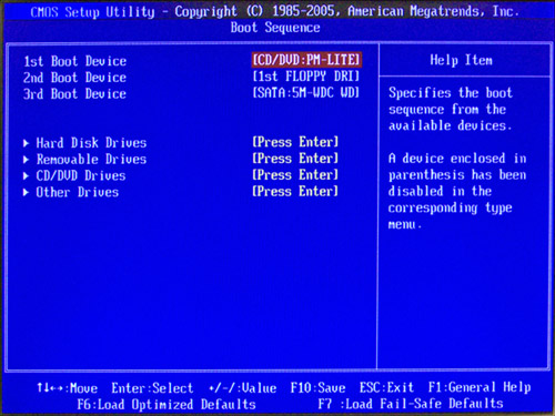
The Boot Sequence submenu shown in Figure 4-9 is used to adjust the order that drives are checked for bootable media. For everyday use, follow this order:
• First drive—Hard disk
• Second—Floppy (if present) or CD/DVD drive
• Third—CD/DVD drive or USB device
Figure 4-9 A typical Boot Sequence submenu configured to permit booting from a CD/DVD or floppy disk.
![]()
Note
Even when the first boot drive is set up as CD/DVD, some discs will prompt the user to press a key in order to boot from the CD/DVD drive when a bootable disk is found. Otherwise, the system checks the next available device for boot files.
The order shown in Figure 4-9 is recommended for situations in which you need to boot from a CD/DVD or floppy disk drive (installing a new operating system or booting diagnostic software).
Note that if you have more than one drive in any category that you can select the boot drive from the submenus below the boot device listing.
Integrated Peripherals
The typical system today is loaded with onboard ports and features, and the Integrated Peripherals menu shown in Figure 4-10 and its submenus are used to enable, disable, and configure them.
Figure 4-10 A typical Integrated Peripherals menu.

Note that most systems have separate settings for USB controller and USB 2.0 controller. If you connect a USB 2.0 device to a USB port on your system and you see a “This device can perform faster” error message in Windows, make sure the USB 2.0 controller or USB 2.0 mode is enabled. If USB 2.0 features are disabled in the BIOS, all of your system’s USB ports will run in USB 1.1 mode only.
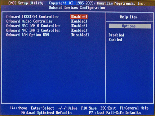
Onboard Devices
The Onboard Devices submenu on this system, shown in Figure 4-11, is used to enable or disable newer types of ports, such as IEEE-1394 (FireWire), audio, and Ethernet LAN ports (this system has two). The onboard LAN option ROM is disabled on this system, but should be enabled if you want to boot from an operating system that is stored on a network drive.
Figure 4.11 A typical Onboard Devices submenu.
I/O Devices
Most systems separate legacy ports such as floppy, serial (COM), and parallel port (LPT) into their own submenus, as in the I/O Devices submenu in Figure 4-12. Some systems might also have a setting for the PS/2 mouse port on this or another CMOS/BIOS menu.
Figure 4-12 A typical I/O Devices submenu.
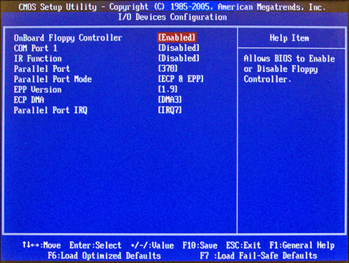
The COM (serial) port is disabled on this system because there are no devices connected to it (most devices that formerly used COM ports, such as modems, pointing devices, and printers, now use USB ports; similarly, most mice that formerly used PS/2 ports now use USB ports). The parallel (LPT) port is enabled because it is used by a printer.
Note
You should disable ports that are not used to make it easier for the system to assign other ports, such as the ones in the Onboard Devices menu, their own hardware resources.
To learn more about ECP, EPP, IRQ, and DMA settings for parallel ports, see Chapter 7, “I/O and Multimedia Ports and Devices.”
PATA/IDE and SATA Configuration
The PATA/IDE and SATA configuration menus usually don’t need adjustment, except when you need to create a redundant array of inexpensive drives (RAID) array from two or more drives. Figure 4-13 shows the SATA configuration menu, and Figure 4-14 shows the PATA/IDE configuration menu.
Figure 4-13 Typical SATA configuration menu.
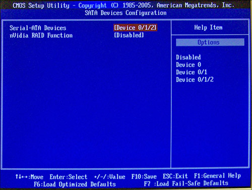
Figure 4-14 Typical PATA configuration menu.

Use the SATA configuration menu to enable, disable, or specify how many SATA host adapters to make available; to enable or disable SATA RAID; and to configure SATA host adapters to run in compatible (emulating PATA) or native (AHCI) mode. AHCI permits hot-swapping of eSATA drives, and the system shown in Figure 4-13 does not list this option. To learn more about RAID configuration, see “Creating an ATA or SATA RAID Array,” in Chapter 12, “Storage Devices.”
Use the PATA configuration menu to enable or disable PATA/IDE host adapters and to enable or disable bus-mastering. Bus-mastering should be enabled, as disabling it causes drive access to be very slow. When bus-mastering (the default on most systems) is enabled, the operating system must load chipset-specific drivers to permit this option to work. Many systems (but not the one shown in Figure 4-14) have two or more PATA host adapters and support RAID functions with PATA drives.
Tip
To assure that the IDE/PATA bus-mastering feature works properly, install the most up-to-date drivers available for the motherboard. Check the motherboard or system vendor’s website for the latest drivers for the version of Windows or other operating system in use.
Power Management
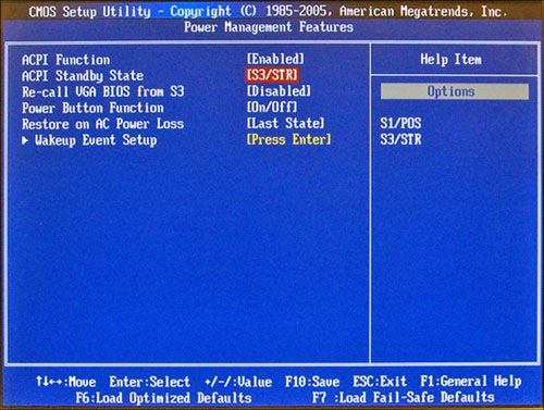
Although Windows includes power management features, the BIOS controls how any given system responds to standby or power-out conditions. Figure 4-15 illustrates a typical power management menu.
Figure 4-15 Typical power management configuration menu.
![]()
ACPI is the power management function used in modern systems, replacing the older APM standard; it should be enabled. Most systems offer two ACPI standby states: S1/POS (power on standby) and S3/STR (suspend to RAM). Use S3/STR whenever possible, as it uses much less power when the system is idle than S1/POS.
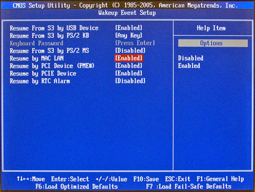
You can also configure your system power button, specify how to restart your system if AC power is lost, and specify how to wake up a system from standby, sleep, or hibernation modes as shown in Figure 4-16.
Figure 4-16 Configuring Wakeup Events.
PnP/PCI Configurations
The PnP/PCI Configuration dialog shown in Figure 4-17 is used to specify which graphics adapter is primary (PCI Express versus PCI or AGP versus PCI), the IRQ settings to use for PCI slots, the settings for the PCI latency timer, and which IRQ and DMA hardware resources to set aside for use by non-PnP devices.
Figure 4-17 Configuring PnP/PCI settings.
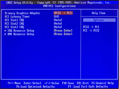
Generally, the default settings do not need to be changed. However, if you need to make a PCI graphics adapter card—rather than a PCI Express or AGP card—the primary graphics adapter, be sure to select PCI->PCIe or PCI->AGP as appropriate.
Note
Most systems have options, as this one does, to reserve IRQ and DMA hardware resources for use by non-PnP adapters, but unless you are managing a system that has non-PnP cards installed (primarily ISA cards, which are now obsolete), there is no need to set aside those resources. If you do set them aside, you must determine the IRQs and DMAs used by these cards and reserve those settings; otherwise, non-PnP cards would not work.
Hardware Monitor
As hot as a small room containing a PC can get, it’s a whole lot hotter inside the PC itself. Excessive heat is the enemy of system stability and shortens the life of your hardware. Adding fans can help, but if they fail, you have problems. See Chapter 5, “Power Supplies and System Cooling,” for more information.
The Hardware Monitor screen (sometimes referred to as PC Health) is a common feature in most recent systems. It helps you make sure that your computer’s temperature and voltage conditions are at safe levels for your computer (see Figure 4-18), and it sometimes also includes the Chassis Intrusion feature.
Figure 4-18 A typical Hardware Monitor screen.

![]()
Although it is useful to view temperature and voltage settings in the BIOS setup program, temperature values are usually higher after the computer has been working for awhile (after you’ve booted to Windows and no longer have access to this screen). Generally, the major value of this screen is that its information can be detected by Windows-based motherboard or system monitoring programs like the one shown in Figure 4-19. These programs enable you to be warned immediately if there are any heat- or fan-related problems with your system.
Figure 4-19 A typical Windows-based hardware monitoring program that displays information from the Hardware Monitor feature in the system BIOS.

Note
Overheating can be caused by improper airflow through the system, a very hot room, or by a power supply that has too low a wattage rating for the devices attached to the power supply (internally or externally).
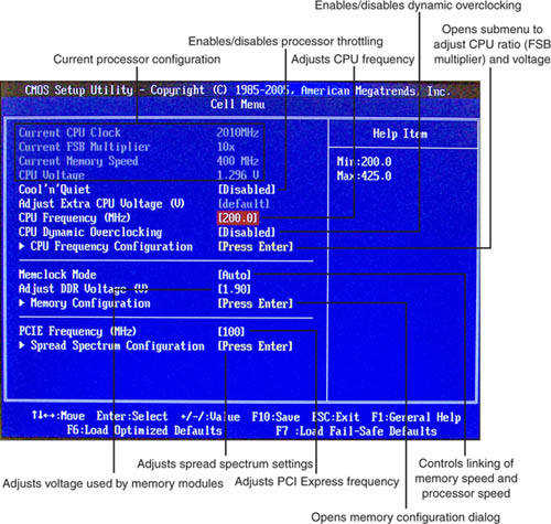
Processor and Memory Configuration
Some older processors, such as the Athlon XP, do not automatically configure the system BIOS settings for processor clock multiplier and frequency, while newer processors typically do. However, the processor configuration dialog shown in Figure 4-20 is found in performance-oriented systems and displays current settings and enables the user to adjust these and other settings to overclock the system (running its components at faster than normal settings).
Figure 4-20 A typical processor configuration screen. Options shown with * are used for overclocking.
![]()
Tip
Some BIOS programs “hide” the processor dialog; you must press a keystroke combination (Control+F1 is a popular choice) to reveal it. BIOS programs in laptops and corporate systems typically don’t include a processor configuration dialog.
Generally, you should not adjust processor or memory timings unless you are trying to overclock a system, or if the system does not properly configure your processor or memory.
Caution
If you make changes to processor or memory settings, and your system no longer boots or is unstable after booting, restart your system, restart the BIOS setup program, and load default or failsafe settings.
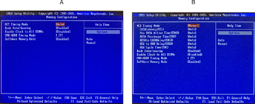
Figure 4-21 shows two views of a typical memory configuration screen. The default Auto MCT Timing Mode (Figure 4-21a) offers limited memory adjustments, while changing the mode to Manual (Figure 4-21b) enables many more settings and is useful primarily for overclocking and maximum-performance situations.
Figure 4-21 A typical memory configuration dialog in auto mode (a) and manual mode (b).
Note
Before making any changes to memory timing, you should find out what memory modules are installed in the system and check the technical specifications at the memory vendor’s website.
Tip
It is not necessary to understand the intricacies of processor and memory overclocking for the A+ Certification exams. If you want to learn more about this topic, some useful websites include Overclockers (www.overclockers.com), Extreme Overclocking (www.extremeoverclocking.com), Maximum PC (www.maximumpc.com; www.maximumpc.com/forums/), and Tom’s Hardware Guide (www.tomshardware.com).
Security Features
Security features of various types are scattered around the typical system BIOS dialogs. These include
• BIOS password— BIOS Settings Password or Security dialogs
• Power-on password— Configured through the Security dialog
• Chassis Intrusion— Various locations
• Boot sector protection— Advanced BIOS Features dialog
For more information about other security features covered on the A+ Certification exams, see Chapter 10, “Security.”
Exiting the BIOS and Saving/Discarding Changes
When you exit the BIOS setup program, you can elect to save configuration changes or discard changes. Choose the option to save changes (Figure 4-22a) if you made changes you want to keep. Choose the option to discard changes (Figure 4-22b) if you were “just looking” and did not intend to make any changes. When you exit the BIOS setup program with either option, the system restarts.
Figure 4-22 Typical exit dialogs: saving changes (a) and discarding changes (b).

![]()
Power-On Self-Test and Error Reporting
Every time you turn on your PC, the BIOS performs one of its most important jobs: the POST (power-on self-test). The POST portion of the BIOS enables the BIOS to find and report errors in the computer’s hardware.
The POST checks the following parts of the computer:
• The CPU and the POST ROM portion of the BIOS
• The system timer
• Video display (graphics) card
• Memory
• The keyboard
• The disk drives
You hope the POST always checks out OK. But what happens if the POST encounters a problem? The system will stop the boot process if it encounters a serious or fatal error (see the following “Beep Codes” section). During the POST process, the BIOS uses any one of several methods to report problems:
• POST error messages (displayed on the monitor)
The next sections describe each method in detail.
Beep Codes
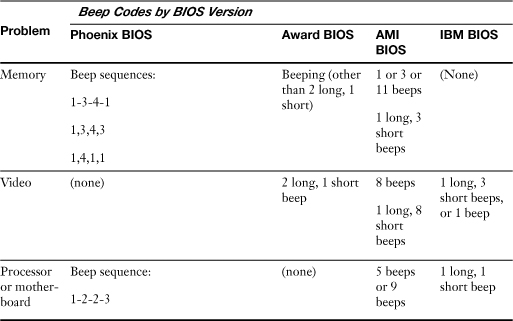
Beep codes are used by most BIOS versions to indicate either a fatal error or a serious error. A fatal error is an error that is so serious that the computer cannot continue the boot process. A fatal error would include a problem with the CPU, the POST ROM, the system timer, or memory. The serious error that beep codes report is a problem with your video display card or circuit. Although systems can boot without video, seldom would you want to because you can’t see what the system is doing.
Beep codes vary by the BIOS maker. Some companies, such as IBM, Acer, and Compaq, create their own BIOS chips and firmware. However, most other major brands of computers and virtually all “clones” use a BIOS made by one of the “Big Three” BIOS vendors: American Megatrends (AMI), Phoenix Technologies, and Award Software (now owned by Phoenix Technologies).
As you might expect, the beep codes and philosophies used by these three companies vary a great deal. AMI, for example, uses beep codes for more than ten fatal errors. It also uses eight beeps to indicate a defective or missing video card. Phoenix uses beep codes for both defects and normal procedures (but has no beep code for a video problem), and the Award BIOS has only a single beep code (one long, two short), indicating a problem with video.
Tip
You can download and play actual audio samples of several beep codes by visiting the official website for this book and registering your book copy. Go to www.informit.com/title/9780789740472 to get started. Check them out!
Because beep codes do not report all possible problems during the startup process, you can’t rely exclusively on beep codes to help you detect and solve system problems.
The most common beep codes you’re likely to encounter are listed in Table 4-4.
Table 4-4 Common System Errors and Their Beep Codes
![]()
Note
For additional beep codes, see the following resources:
• AMI BIOS— http://www.ami.com/support/bios.cfm
• Phoenix BIOS— http://www.phoenix.com/
• IBM, Dell, Acer, other brands— http://www.bioscentral.com
Note
Don’t mix up your boops and beeps! Many systems play a single short boop (usually a bit different in tone than a beep) when the system boots successfully. This is normal.
POST Error Messages
Most BIOS versions do an excellent job of displaying POST error messages indicating what the problem is with the system. These messages can indicate problems with memory, keyboards, hard disk drives, and other components. Some systems document these messages in their manuals, or you can go to the BIOS vendors’ website for more information.
Note
Keep in mind that the system almost always stops after the first error, so if a system has more than one serious or fatal error, the first problem will stop the boot process before the video card has been initialized to display error messages.
POST Hex Codes
There are beep codes and text messages to tell you that there’s a problem with your computer, but there’s also a third way your PC can let you know it needs help: by transmitting hexadecimal codes to an I/O port address (usually 80h) that indicate the progress of testing and booting. The hexadecimal codes output by the BIOS change rapidly during a normal startup process as different milestones in the boot process are reached. These codes provide vital clues about what has gone wrong when your system won’t boot and you don’t have a beep code or onscreen message to help you. It would be handy if systems included some way to view these codes, but most do not (a few systems include a four-LED header cable that displays boot progress, but this is only a partial solution for a system that won’t start properly).
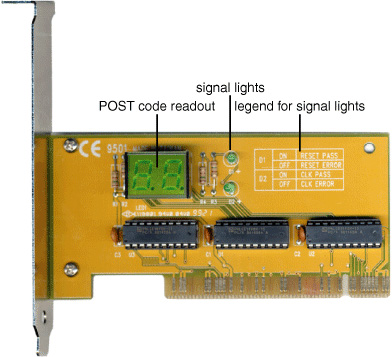
To monitor these codes, you need a POST card such as the one shown in Figure 4-23, available from a variety of vendors, including JDR Microdevices (www.jdr.com) and Ultra-X (www.ultra-x.com). These cards are available in versions that plug into either the now-obsolete ISA slot or into PCI or PCI Express x1 expansion slots. The simplest ones have a two-digit LED area that displays the hex codes, whereas more complicated (and expensive) models also have additional built-in tests. Some vendors also offer POST display devices that plug into parallel ports; these are useful for monitoring system startup without opening the case on both desktop and portable systems that include parallel ports.
Figure 4-23 This POST card plugs into a PCI slot.
The same hex code has different meanings to different BIOS versions. For example, POST code 31h means “display (video) memory read/write test” on an AMI BIOS, but it means “test base and extended memory” on the Award BIOS, and it is not used on Phoenix BIOS. As with other types of error messages, check your manual or the BIOS manufacturer’s website for the meaning of any given code.
Tip
The worst time to learn how to interpret a POST card is when your system’s sick. On the other hand, the best way to learn to use a POST card is to plug it into a healthy system and watch the codes change during a normal system startup. Typically, the codes change very quickly until the final code (often “FF”) is reached and the system starts. On a defective system, the codes will pause or stop when a defective item on the system is tested. The cards don’t need to be left in systems routinely.
BIOS Updates
The BIOS chip can be regarded as the “glue” that binds the hardware to the operating system. If the BIOS doesn’t recognize the operating system or the hardware it communicates with, you’re sure to have problems.
Because the BIOS chip bridges hardware to the operating system, you will need to update the BIOS whenever your current BIOS version is unable to properly support
• New hardware, such as large SATA and PATA/IDE hard drives and different types of removable-storage drives
• Faster CPUs
• New operating systems and features
• New BIOS options
Although software drivers can be used as workarounds for hard drive BIOS limitations, a true BIOS update is the best solution for hard disk control, and the only solution if your BIOS can’t handle new processors or operating systems.
If you keep your computer for more than a year or so, or if you decide to install a new processor, you might need to upgrade the BIOS. Back in the 1980s into the early 1990s, a BIOS update required a physical chip swap and, sometimes, reprogramming the chip with a device called an electrically erasable programmable read only memory (EEPROM) burner. If the replacement or reprogrammed BIOS chip was installed incorrectly into the socket, it could be destroyed.
Fortunately, since the mid-1990s, a BIOS update can now be performed with software. The Flash BIOS chips in use on practically every recent system contain a special type of memory that can be changed through a software download from the system or motherboard maker.
Although Flash BIOS updates are easier to perform than the older replace-the-chip style, you still need to be careful. An incomplete or incorrect BIOS update will prevent your system from being accessed. No BIOS, no boot! Regardless of the method, for maximum safety, I recommend the following initial steps:
Step 1. Back up important data.
Step 2. Record the current BIOS configuration, especially hard disk settings as discussed earlier in this chapter.
Caution
BIOS configuration information might need to be re-entered after a BIOS update, especially if you must install a different chip.
Flash BIOS Update
So, you’ve decided you need a Flash BIOS update. Where do you get it? Don’t ask the BIOS manufacturers (Phoenix, AMI, and Award/Phoenix). They don’t sell BIOS updates because their basic products are modified by motherboard and system vendors.
Here are the general steps for performing a Flash BIOS update:
Step 1. For major brands of computers, go to the vendor’s website and look for “downloads” or “tech support” links. The BIOS updates are listed by system model and by version; avoid beta (pre-release) versions.
Tip
If your system is a generic system (that is, it came with a “mainboard” or “motherboard” manual and other component manuals rather than a full system manual), you need to contact the motherboard maker. Some systems indicate the maker during bootup. Others display only a mysterious series of numbers. You can decode these numbers to get the motherboard’s maker. See the following websites for details:
• Wim’s BIOS page (www.wimsbios.com)
• eSupport (www.biosagentplus.com)
• American Megatrend’s BIOS Support page (www.ami.com/support/bios.cfm)
You can also buy replacement flash BIOS code from eSupport if you are unable to get updated BIOS code from your system or motherboard vendor.
Step 2. Download the correct BIOS update for your system or motherboard. For generic motherboards, Wim’s BIOS page also has links to the motherboard vendors’ websites.
Step 3. You might also need to download a separate loader program, or the download might contain both the loader and the BIOS image. If the website has instructions posted, print or save them to a floppy disk for reference.
Step 4. Next, install the BIOS update loader and BIOS image to a floppy disk. Follow the vendor’s instructions.
Note
Some BIOS updates can be done within Windows XP and Vista. If this is the case, just double-click the BIOS executable to begin the upgrade; a system restart will be necessary.
Step 5. After installation is complete, restart your system with the floppy disk containing the upgrade; make sure the floppy disk is the first item in the BIOS boot sequence. Press a key if necessary to start the upgrade process.
Some upgrades run automatically; others require that you choose the image from a menu, and still others require the actual filename of the BIOS. The BIOS update might also prompt you to save your current BIOS image to a floppy disk. Choose this option if possible so you have a copy of your current BIOS in case there’s a problem.
Step 6. After the update process starts, it takes about three minutes to rewrite the contents of the BIOS chip with the updated information.
Caution
While performing a Flash upgrade, make sure that you don’t turn off the power to your PC and that you keep children or pets away from the computer to prevent an accidental shutdown (read: your four-year-old decides to unplug the computer). Wait for a message indicating the BIOS update has been completed before you even think about touching the computer. If the power goes out during the Flash update, the BIOS chip could be rendered useless.
Step 7. Remove the floppy disk and restart the system to use your new BIOS features. Reconfigure the BIOS settings if necessary.
Tip
Some motherboards have a jumper on the motherboard that can be set to write-protect the Flash BIOS. Take a quick look at your documentation before you start the process and disable this jumper first. Then, re-enable the write-protect jumper after you’re done with the upgrade.
BIOS Chip Replacement
On motherboards whose BIOS programs can’t be upgraded with software, you might be able to purchase a replacement BIOS from vendors such as eSupport or BIOSMAN (www.biosman.com). Before you order a BIOS chip replacement, consider the following:
• BIOS chip upgrades cost about $30–40 each.
• Although the BIOS will be updated, the rest of the system might still be out of date. If your system is more than two years old and is not fast enough for your needs, you might be better off buying a replacement motherboard or system.
• A replacement BIOS enables you to improve system operation without reinstalling Windows.
If you still need to update the BIOS chip itself, first verify that the vendor has the correct BIOS chip replacement. The replacement needs to
• Plug into your current motherboard; as you saw in Figure 4-1, some BIOS chips are square, while others are rectangular.
• Support your motherboard/chipset.
• Provide the features you need (such as support for larger hard disks, particular processor speeds, and so on).
It might be a different brand of BIOS than your current BIOS. If so, make sure that you have recorded your hard drive information. You will need to re-enter this and other manually configured options into the new BIOS chip’s setup program.
How does the BIOS vendor know what your system uses? The vendor will identify the BIOS chip you need by the motherboard ID information displayed at bootup. eSupport offers a free download utility to display this information for you. To replace the chip, follow these steps:
Step 1. Locate the BIOS chip on your motherboard after you open the case to perform the upgrade. It sometimes has a sticker listing the BIOS maker and model number. If not, go to Step 2.
Step 2. Socketed BIOS chips might be in a DIP-type package (rectangular with legs on two sides) or in a PLCC (Plastic Leaded Chip Carrier; square with connectors on four sides). Refer to Figure 4-1. The vendor typically supplies a chip extraction tool to perform the removal.
Step 3. Use the chip extraction tool to remove the BIOS chip. Don’t try to remove the chip all at once; gently loosen each connected side until the chip can be lifted free.
Step 4. Remove the existing BIOS chip carefully and put it on antistatic material in case you need to reuse it in that system.
Step 5. Align the new BIOS chip with the socket. Note that a DIP-type BIOS can be installed backward (which will destroy the chip when power is turned on), so be sure to align the dimpled end of the chip with the cutout end of the socket. PLCC BIOS chips have one corner cut out.
Step 6. Adjust the legs on a new DIP-type BIOS chip so it fits into the sockets, and press it down until the legs on both sides are inserted fully. Press the PLCC BIOS chip into the socket.
Step 7. Double-check the alignment and leg positions on the BIOS chip before you start the system; if the chip is aligned with the wrong end of the socket, you’ll destroy it when the power comes on.
Step 8. Turn on the system, and use the new BIOS’s keystroke(s) to start the setup program to re-enter any information. You might get a “CMOS” error at startup, which is normal with a new BIOS chip. After you re-enter the BIOS data from your printout and save the changes, the system will run without error messages.
Note
A “CMOS Checksum” error is normal after you replace the BIOS chip. However, after you run the BIOS setup program and save the settings, this error should go away. If you continue to see this error, test the motherboard battery. If the battery checks out okay, contact the motherboard or system vendor for help.
Exam Preparation Tasks
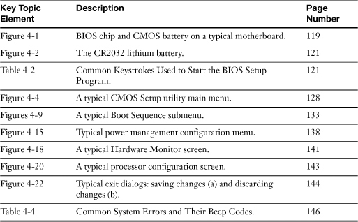
Review All the Key Topics
Review the most important topics in the chapter, noted with the key topics icon in the outer margin of the page. Table 4-4 lists a reference of these key topics and the page numbers on which each is found.
Table 4-5 Key Topics for Chapter 4
Complete the Tables and Lists from Memory
Print a copy of Appendix B, “Memory Tables,” (found on the CD), or at least the section for this chapter, and complete the tables and lists from memory. Appendix C, “Memory Tables Answer Key,” also on the CD, includes completed tables and lists to check your work.
Definitions of Key Terms
Define the following key terms from this chapter, and check your answers in the glossary.
BIOS,
POST,
Troubleshooting Scenario
You have just started up your computer. It gives off a series of loud beeps and will not boot. What would you need to do to determine what the beeps mean and how to fix the problem?
Refer to Appendix A, “Answers to the ‘Do I Know This Already?’ Quizzes and Troubleshooting Scenarios,” for the answer.