
Chapter 1. PC Technician Essentials
Before you can open a computer to work on it, it’s important to have the proper PC tools, and to know how to eliminate electrostatic discharge (ESD). When working with computers it is also important to understand some fundamentals about computer terms and technologies. This chapter provides you with the foundation needed for the chapters that follow by making sure you understand the basic tools, computer terms, and concepts.
This chapter touches on several fundamental computer concepts, most of which are covered in more depth later in the book. Having a good grasp of these fundamentals is essential for fully understanding the concepts discussed in this book and for putting them into practice in the real world. If you feel you have sufficient understanding of these essential topics, you may choose to skip ahead to Chapter 2, “PC Anatomy 101.”
PC Tools
A technician’s best tools are his or her senses and hands. However, a technician needs hardware tools to open the PC and to install and replace components. There are several personal computer (PC) tools that should be a part of every technician’s toolkit including
• Phillips and straight-blade screwdrivers— Used when hex drivers are not compatible; non-magnetic preferred
• Torx drivers— Required for some Compaq models; non-magnetic preferred
• Hex drivers— Used for opening and closing cases and securing and removing cards and motherboards; non-magnetic preferred
• 3-claw parts retrieval tool— Retrieves loose parts from computer interior; prevents lost parts, which can lead to dead shorts
• Hemostat clamps— Replaces tweezers for inserting and removing jumper blocks and cables
• Needle-nose pliers— Straightens bent pins
• Eyebrow tweezers— Replaces normal tweezers in toolkit for removing and replacing jumpers
• Penlight— Illuminates dark cases
• Magnifier— Makes small parts and markings easier to read
• Jeweler’s screwdriver set— Enables repairs to devices that use small screws
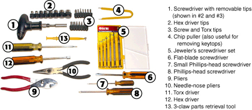
You can buy toolkits that contain many of these items, but don’t hesitate to supplement a kit you already have with additional items from this list or other items you find useful. Figure 1-1 illustrates some important tools.
Figure 1-1 Typical tools used by computer technicians.
Preventing Electrostatic Discharge
Electrostatic discharge (ESD) occurs when two objects of different voltages come into contact with each other. The human body is always gathering static electricity, more than enough to damage a computer component. ESD is a silent killer. If you were to touch a component without proper protection, the static electricity could discharge from you to the component, most likely damaging it, but with no discernable signs of damage. Worse yet, it is possible to discharge a small amount of voltage to the device and damage it to the point where it works intermittently, making it tough to troubleshoot. It only takes 30 volts or so to damage a component. On a dry winter day, you could gather as much as 20,000 volts when walking across a carpeted area! Ouch! There are several ways to equalize the electrical potentials, allowing you to protect components from ESD:
• Use an antistatic wrist strap— The most common kind is inexpensive and only takes a moment to put on and connect to the chassis of the computer (an unpainted portion of the frame inside the case). By using an antistatic wrist strap you are constantly discharging to the case’s metal frame instead of to the components that you handle. Of course, the chassis of the computer can only absorb so much ESD, so consider another earth-bonding point to connect to or try to implement as many other antistatic methods as possible. Most wrist straps come equipped with a resistor (often 1 megaohm) that protects the user from shock hazards when working with low-voltage components.
More advanced types of wrist straps are meant to connect to an actual ground; a ground strip or the ground plug of a special dedicated AC outlet. These are used in more sophisticated repair labs. Do not attempt to connect the alligator clip of a basic wrist strap (purchased at an office store), to the ground plug of an outlet in your home.
• Touch the chassis of the computer— Do this to further discharge yourself before handling any components. This is also a good habit to get into for those times when an anti-static strap is not available.
• Use an antistatic mat— Place the computer on top of the antistatic mat and connect the alligator clip of the mat to the computer’s chassis in the same manner that you did with the wrist strap. (Some people stand on the mat and connect it to the computer.)
• Use antistatic bags— Adapter cards, motherboards, and so on are normally shipped in antistatic bags. Hold on to them! When installing or removing components, keep them either inside or on top of the bag until you are ready to work with them.
Remember: ESD need only happen once, and that $500 video card you are trying to install is toast!
The CompTIA Six-Step Troubleshooting Process
It is necessary to approach computer problems from a logical standpoint. To best accomplish this, PC technicians will implement a troubleshooting methodology (or maybe more than one). CompTIA has included a six-step process within the 2009 A+ objectives. Memorize the steps listed in Table 1-1.
Table 1-1 The Six-Step CompTIA A+ Troubleshooting Methodology
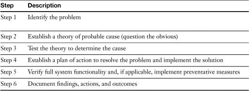
As you attempt to troubleshoot computer issues, think in terms of this six-step process. Plug the problem directly into these steps. If you test a theory in Step 3, and the theory is disproved, return to Step 2 and develop another theory. Continue in this manner until you have found a theory that is plausible.
Numbering Systems Used in Computers
Since the development of the first personal computers (PCs) more than 30 years ago, many terms such as bits, bytes, decimal, binary, and hexadecimal have become part of common language. However, these terms are not always used correctly. This section helps you understand what these terms and numbering systems mean and how they relate to the PC technologies you will be studying in future chapters.
Three numbering systems are used in computers: decimal, binary, and hexadecimal. You already are familiar with the decimal system: Look at your hands. Now, imagine your fingers are numbered from 0–9, for a total of 10 places. Decimal numbering is sometimes referred to as base 10.
The binary system doesn’t use your fingers; instead, you count your hands: One hand represents 0, and the other 1, for a total of two places. Thus, binary numbering is sometimes referred to as base 2.
The hexadecimal system could be used by a pair of spiders who want to count: One spider’s legs would be numbered 0–7, and the other spider’s legs would be labeled 8, 9, A–F to reach a total of 16 places. Hexadecimal numbering is sometimes referred to as base 16.
Tip
Although all data in the computer is stored as a stream of binary values (0s and 1s), most of the time you will use decimal (“512 MB of RAM”) or hexadecimal (“memory conflict at C800 in upper memory”) measurements. The typical rule of thumb is to use the system that produces the smallest meaningful number. If you need to convert between these systems, you can use any scientific calculator, including the Windows Calculator program (select View, Scientific from the menu).
Decimal Numbering System
We use the decimal or base 10 system for everyday math. A variation on straight decimal numbering is to use “powers of 2” as a shortcut for large values. For example, drive storage sizes often are defined in terms of decimal bytes, but the number of colors that a video card can display can be referred to as “24-bit” (or 224), which is the same as 16,777,216 colors.
Binary Numbering System
All data is stored in computers in a stream of 1s (on) and 0s (off). Because only two characters (0 and 1) are used to represent data, this is called a “binary” numbering system. Text is converted into its numerical equivalents before it is stored, so binary coding can be used to store all computer data and programs.
Table 1-2 shows how you would count from 1 to 10 (decimal) in binary.
Table 1-2 Decimal Numbers 1–10 and Binary Equivalents

Because even a small decimal number occupies many places if expressed in binary, binary numbers are usually converted into hexadecimal or decimal numbers for calculations or measurements. Binary numbers are also the basis for bits and bytes: a single binary value is represented by a bit, and eight bits equals a byte.
Note
Once you understand how binary numbering works, you can appreciate the joke going around the Internet and showing up on T-shirts near you:
“There are 10 kinds of people in the world—those who understand binary and those who don’t.”
T-shirts are available from ThinkGeek (www.thinkgeek.com).
There are several ways to convert a decimal number into binary:
• Use a scientific calculator with conversion
• Use the division method
• Use the subtraction method
To use the division method, follow these steps:
Step 1. Divide the number you want to convert by 2.
Step 2. Record the remainder: If there’s no remainder, enter 0. If there’s any remainder, enter 1.
Step 3. Divide the resulting answer by 2.
Step 4. Repeat the process, recording the remainder each time.
Step 5. Repeat the process until you divide 0 by 2. This is the last answer.
Step 6. When the last answer is divided, the binary is recorded from Least Significant Bit (LSB) to Most Significant Bit (MSB). Reverse the order of bit numbers so that MSB is recorded first and the conversion is complete. For example, to convert the decimal number 115 to binary using the division method, follow the procedure shown in Figure 1-2.
Figure 1-2 Converting decimal 115 to binary with the division method.

If you use a scientific calculator (such as the scientific mode of the Windows Calculator) to perform the conversion, keep in mind that any leading zeros will be suppressed. For example, the calculation in Figure 1-2 indicates the binary equivalent of 115 decimal is 01110011. However, a scientific calculator will drop the leading zero and display the value as 1110011.
To use the subtraction method, follow these steps:
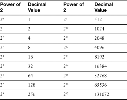
Step 1. Look at the number you want to convert and determine the smallest power of two that is greater than or equal to the number you want to subtract. Table 1-3 lists powers of two from 20 through 217. For example, 115 decimal is less than 27 (128) but greater than 26 (64).
Step 2. Subtract the highest power of two from the value you want to convert. Record the value and write down binary 1.
Step 3. Move to the next lower power of two. If you can subtract it, record the result and also write down binary 1. If you cannot subtract it, write down binary 0.
Step 4. Repeat Step 3 until you attempt to subtract 20 (1). Again, write down binary 1 if you can subtract it or binary 0 if you cannot. The binary values (0 and 1) you have recorded are the binary conversion for the decimal number. Unlike the division method, this method puts them in the correct order; there’s no need to write them down in reverse order.
For example, to convert 115 decimal to binary using the subtraction method, see Figure 1-3.
Figure 1-3 Converting 115 decimal to binary with the subtraction method.

Tip
Table 1-3 provides a listing of powers of 2, but you can use the Windows Calculator in scientific view mode to calculate any power of two you want. To open the Windows Calculator click Start, then Run and type calc.exe. (If you cannot see the Run option in Windows Vista, press the Windows key and R simultaneously.) Just enter 2, click the x^y button, and enter the value for the power of 2 you want to calculate (such as 24). The results are displayed instantly (you add the commas). Use the Edit menu to copy the answer to the Windows Clipboard, and use your program’s Paste command to bring it into your document. Sure beats counting on your fingers!
Caution
You might need to convert decimal to binary numbers for the A+ Certification exam, so try both pencil and paper methods (division and subtraction) and get comfortable with one of them.
Binary Versus Decimal MB/GB
Although a byte represents the basic “building block” of storage and RAM calculation, most measurements are better performed with multiples of a byte. All calculations of the capacity of RAM and storage are done in bits and bytes. Eight bits is equal to one byte.
Table 1-4 provides the most typical values and their relationship to the byte.
Table 1-4 Decimal and Binary Measurements

Consider a hard disk rated by its maker as 160 GB (decimal). This is 160,000,000,000 bytes (decimal). However, when the drive is detected and configured by the BIOS and partitioned with FDISK, its size is listed as only 149.01 GB (binary GB). At first glance, you might believe you’ve lost some capacity (see Figure 1-4).
Figure 1-4 The capacity of an 160 GB hard disk size is 160 billion bytes (top bar), but most BIOS programs and Windows FDISK/Disk Management measure drives in binary gigabytes (bottom bar) and report a capacity of 149.01GB.

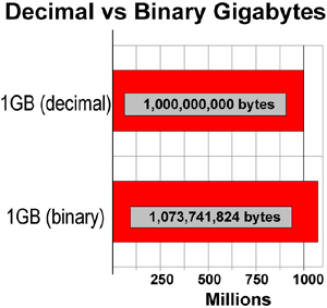
However, as you’ve already seen, there is a substantial difference between the number of bytes in a binary gigabyte and one billion bytes. This different numbering system, not any loss of bytes, accounts for the seeming discrepancy. Use this information to help explain to a customer that the “missing” capacity of the hard disk isn’t really missing (see Figure 1-5).
Figure 1-5 A binary gigabyte has over 73 million more bytes than a decimal gigabyte (1 billion bytes).
Data Storage and Overhead
As you learned earlier in this chapter, bits and bytes are the building blocks of measuring storage and memory capacities. However, why is it that when the same information is stored in different ways that the size of the file changes so much?
If you are storing text-only information in the computer, each character of that text (including spaces and punctuation marks) equals a byte. Thus, to calculate the number of bytes in the following sentence, count the letters, numbers, spaces, and punctuation marks:
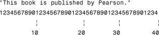
From the scale you can see that the sentence uses 43 bytes. You can prove this to yourself by starting up Windows Notepad and entering the text just as you see it printed here. Save the text as EXAMPLE.TXT and view the File properties. You’ll see that the text is exactly 43 bytes.
Do most computer programs store just the text when you write something? To find out, start up a word-processing program, such as Windows WordPad or Microsoft Word. Enter the same sentence again, and save it as EXAMPLE. If you use WordPad, save the file as a Rich Text Format (.RTF) file. Depending upon the exact version of WordPad or Microsoft Word you use, the file takes up much more space. For example, WordPad for Windows XP saves text as an RTF file, using 252 bytes to store the file. The same sentence takes 24,576 bytes when saved as a .DOC file by Microsoft Word 2002!
When data you create is stored in a computer, it must be stored in a particular arrangement suitable for the program that created the information. This arrangement of information is called the file format.
A few programs, such as Windows Notepad, store only the text you create. What if you want to boldface a certain word in the text? A text-only editor can’t do it. All that Edit and Notepad can store is text. As you have seen, in text-only storage, a character equals a byte.
In computer storage, however, pure text is seldom stored alone. WordPad and other word-processing programs such as Microsoft Word, OpenOffice Writer, and Corel WordPerfect enable you to boldface, underline, italicize, and make text larger or smaller. You can also use different fonts in the same document.
Most modern programs also enable you to insert tables, create columns of text, and insert pictures into the text. Some, such as Microsoft Word, have provisions for tracking changes made by different users. In other words, there’s a whole lot more than text in a document.
To keep all this non-text information arranged correctly with the text, WordPad and other programs must store references to these additional features along with the text, making even a sentence or two into a relatively large file, even if none of the extra features is actually used in that particular file. Thus, for most programs, the bytes used by the data they create are the total of the bytes used by the text or other information created by the program and the additional bytes needed to store the file in a particular file format.
Because different programs store data in different ways, it’s possible to have an apparent software failure take place because a user tries to use program B to open a file made with program A. Unless program B contains a converter that can understand and translate how program A stores data, program B can’t read the file, and might even crash. To help avoid problems, Windows associates particular types of data files with matching programs, enabling you to open the file with the correct program by double-clicking the file in Explorer or File Manager.
Hexadecimal Numbering System
A third numbering system used in computers is hexadecimal. Hexadecimal numbering is also referred to as base 16, a convenient way to work with data because 16 is also the number of bits in 2 bytes or 4 nibbles (a nibble being 4 bits). Hexadecimal numbers use digits 0–9 and letters A–F to represent the 16 places (0–15 decimal). Hexadecimal numbers are used to represent locations in data storage, data access, and RAM. Table 1-5 shows how decimal numbers are represented in hex.
Table 1-5 Decimal and Hexadecimal Equivalents

The most typical uses for hexadecimal numbering are
• Upper memory addresses
• I/O port addresses
• MAC addresses and IPv6 addresses
Measuring Data Transfer and Frequency
Data is constantly being transferred within a computer and between computers. But how much data, and how fast is it being computed? Data transfer is known as bandwidth, which specifies how much data is being sent per second. The speed at which data is computed is known as Hertz, which also dictates the frequency used to transfer data.
Bandwidth
Other than bits and bytes and their multiples, probably the second most significant concept to understand about computer measurements is bandwidth, also known as data transfer rate. Bandwidth refers to the amount of information that can be sent or received through a computer or network connection in one second. This can be measured in bits (with a lower case b) or bytes (with an upper case B). For example, the bandwidth of a USB 1.1 port running at full speed transfers a maximum of 11 megabits per second (11 Mbps, notice the lower case b), while the bandwidth of a USB 2.0 port running at high speed is 480 Mbps, and a user might download 300 kilobytes (300 KB/s, notice the upper case B) of data per second. Or an expansion card that goes into a PCI slot could transfer a maximum of 266 MB/s.
Bandwidth measurements like this are used for measuring the performance of serial, parallel, wired and wireless network connections, expansion slots (PCI, PCIe, and AGP), hard disk interfaces (PATA and SATA), and multipurpose device interfaces (SCSI, USB, and FireWire). It defines the amount of information that can flow through the computer.
Information flows through the computer in many ways. The CPU is the central point for most information. When you start a program, the CPU instructs the storage device to load the program into RAM. When you create data and print it, the CPU instructs the printer to output the data.
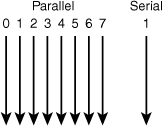
Because of the different types of devices that send and receive information, two major types of data transfers take place within a computer: parallel and serial. These terms are used frequently, but if you’re not familiar with the differences between them, check out Figure 1-6.
Figure 1-6 Parallel data transfers move data 8 bits at a time, whereas serial data transfers move 1 bit at a time.
Parallel Information Transfers
Parallel transfers use multiple “lanes” for data and programs, and in keeping with the 8 bits = 1 byte nature of computer information, most parallel transfers use multiples of 8. Parallel transfers take place between the following devices:
• Processor (CPU) and RAM
• Processor (CPU) and interface cards
• LPT (printer) port and parallel printer
• SCSI port and SCSI devices
• PATA /IDE host adapter and PATA/IDE drives
• RAM and interface cards, either via the CPU or directly with direct memory access (DMA)
Before the development of high-speed interfaces such as serial ATA (SATA), universal serial bus (USB), and FireWire (IEEE 1394), parallel interfaces were the most common types of interfaces between peripherals and PC components. There were two reasons for this:
• Multiple bits of information are sent at the same time.
• At identical clock speeds, parallel transfers are faster than serial transfers because more data is being transferred.
However, parallel transfers also have problems:
• Many wires or traces (wire-like connections on the motherboard or expansion cards) are needed, leading to interference concerns and thick, expensive cables.
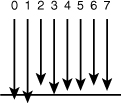
• Excessively long parallel cables or traces can cause data to arrive at different times. This is referred to as signal skew (see Figure 1-7).
Figure 1-7 Parallel cables that are too long can cause signal skew, allowing the parallel signals to become “out of step” with each other.
• Differences in voltage between wires or traces can cause jitter.
As a result of these problems some compromises have had to be included in computer and system design:
• Short maximum lengths for parallel, PATA/IDE, and SCSI cables
• Dual-speed motherboards (running the CPU internally at much faster speeds than the motherboard or memory)
Fortunately, there is a second way to transmit information: serial transfers.
Serial Transfers
A serial transfer uses a single “lane” in the computer for information transfers. This sounds like a recipe for slowdowns, but it all depends on how fast the speed limit is on the “data highway.”
The following ports and devices in the computer use serial transfers:
• Serial (also called RS-232 or COM) ports and devices
• Modems (which can be internal devices or can connect to serial or USB ports)
• USB (Universal Serial Bus) 1.1 and 2.0 ports and devices
• IEEE 1394 (FireWire, i.Link) ports and devices
• Serial ATA (SATA) host adapters and drives
Serial transfers have the following characteristics:
• One bit at a time is transferred to the device.
• Transmission speeds can vary greatly, depending on the sender and receiver.
• Very few connections are needed in the cable and ports (one transmit, one receive, and a few control and ground wires).
• Cable lengths can be longer with serial devices. For example, an UltraDMA/133 PATA/IDE cable can be only 18 inches long for reliable data transmission, whereas a Serial ATA cable can be almost twice as long.
Although RS-232 serial ports are much slower than any parallel interface, newer types of devices using serial transfers such as USB, SATA, and FireWire are much faster than parallel devices. The extra speed is possible because serial transfers don’t have to worry about interference or other problems caused by running so many data lines together. As a result, parallel interfacing is used primarily for some types of internal connections between motherboard devices, while USB, SATA, and FireWire have almost completely replaced serial, parallel, PATA/IDE, and SCSI interfaces.
Tip
Parallel data transfers are measured in bytes, serial data transfers are measured in bits.
Hertz (Hz)
Hertz (Hz) measures the transmission frequency of radio and electrical signals in cycles per second. For example, the common 115V alternating current (AC) electrical standard used in North America is transmitted at 60 cycles per second, or 60 Hz; thus, 115V/60Hz AC.
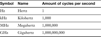
Megahertz (MHz) is equal to 1000 Hz; Gigahertz (GHz) is equal to 1000 MHz or one million Hz. An example of a device that runs in the GHz speeds is the processor or CPU; a typical CPU might run at 2.4 GHz. Table 1-6 shows the most common multiples for Hertz.
At this point you should have a nice little foundation of knowledge concerning PC tools, electrostatic discharge, troubleshooting, numbering systems, and data transfer. Memorize and use these concepts as you read through the upcoming chapters to help you understand the more in-depth concepts that you will encounter.
Important Websites
There are several websites that we will be referring to within this book; you will be accessing these websites quite frequently when working in the field. They include
• Microsoft’s TechNet— http://technet.microsoft.com. This site includes highly technical information about all of Microsoft’s products.
• Microsoft Help and Support— http://support.microsoft.com (previously known as the Microsoft Knowledge Base or MSKB). This site has thousands of articles that show how to configure and troubleshoot Windows.
• CompTIA’s A+ webpage— http://www.comptia.org/certifications/listed/a.aspx. This site describes the CompTIA A+ certification and how the exam works, and it has downloadable objectives that show exactly what is on the exam.