
Chapter 9. Laptops and Portable Devices
This chapter covers a portion of the CompTIA A+ 220-701 objectives 1.10 and 2.4, and CompTIA A+ 220-702 objective 1.3.
Laptops were originally designed for niche markets, but today they are used in businesses almost as much as regular PCs are. Laptops (also known as notebooks or portable computers) have integrated displays, keyboards, and pointing devices, which makes them easy to transport and easy to use in confined spaces. There are plenty of other portable devices on the market today, including PDAs, Ultra-Mobile PCs, and more, but the bulk of the portable devices that you will troubleshoot are laptops. For the A+ exams it is important to know the components of a laptop, how to safely remove hardware, the ports that surround the machine, and care and preventative maintenance of the laptop.
“Do I Know This Already?” Quiz
The “Do I Know This Already?” quiz allows you to assess whether you should read this entire chapter or simply jump to the “Exam Preparation Tasks” section for review. If you are in doubt, read the entire chapter. Table 9-1 outlines the major headings in this chapter and the corresponding “Do I Know This Already?” quiz questions. You can find the answers in Appendix A, “Answers to the ‘Do I Know This Already?’ Quizzes and Troubleshooting Scenarios.”
Table 9-1 “Do I Know This Already?” Foundation Topics Section-to-Question Mapping

1. To save space on most laptops, the computer keyboards have fewer keys than desktop computers have. Which of the following is an example of a key that saves space?
a. The F keys
b. Fn key
c. Num Lock key
d. Delete key
2. What type of laptop memory is installed in all newer model laptops?
a. DIMMs
b. SIMMs
c. SDRAM
d. SODIMMs
3. What is the size of a typical laptop hard drive?
a. 3.5 in
b. 2.5 in
c. 5.5 in
d. 4.5 in
4. Which technology can be used to expand the capability of a portable computer?
a. A docking station
b. A laptop case
c. A smart card
d. None of these options is correct
5. Which of the following is referred to as an expansion slot for laptops?
a. PCI card
b. AGP card
c. PCI Express card
d. PCMCIA
6. Which of the following are considered input devices? (Choose all that apply.)
a. A mouse
b. A keyboard
c. A stylus
d. A printer
7. What technique is used for the processor to run at lower clock speed when processor loads are light and to run at higher clock speeds when processor loads increase?
a. Memory optimizing
b. CPU filtering
c. Processor throttling
d. Load balancing
8. Which of the following technologies can you find on newer laptops today? (Choose all that apply.)
a. Bluetooth
b. Infrared
c. Wireless cards
d. Ethernet
9. Which type of built-in mouse equivalent do laptops commonly use? (Choose the best answer.)
a. Roller ball
b. Touch pad
c. Stylus
d. Pointing stick
10. Which tab would you use to configure user alerts and automatic actions to take when the system reaches low or critical battery power levels?
a. Advanced tab
b. Suspend tab
c. Power Schemes tab
d. Alarms tab
11. Which of the following can automatically locate wireless networks in Windows?
a. Ethernet
b. Bluetooth Devices applet
c. Wireless Zero Configuration
d. WPA2
12. When working with laptops, what is the safe removal standard for a PC card? (Choose two.)
a. Look for the ejector button
b. Update the drivers
c. Turn off laptop
d. Disconnect any cables from the card
13. Which of the following are ways to troubleshoot power problems on a laptop?
a. Use a multimeter
b. Turn off the computer
c. Make sure the laptop is unplugged
d. None of these options is correct
14. Which of the following can cause a laptop to have stop errors that are sometimes called the blue screen of death?
a. Blocked cooling fan
b. Cooling fan failure
c. Damage to the heat sink
d. All these options are correct
Foundation Topics
Fundamental Features of Laptops and Portable Devices
What makes portable computers different than desktop computers? They perform the same types of tasks, but their hardware differs. See Table 9-2 for a comparison of desktop computers and portable computers.
Table 9-2 Portable and Desktop Computers Comparison by Features

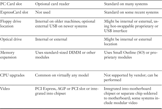
![]()
A typical portable computer has the following components:
• Integrated LCD display
• Integrated keyboard with pointing device
• Standard I/O ports (USB, PS/2 mouse and keyboard; some might also include serial and parallel)
• PC Card (CardBus) or ExpressCard expansion slot
• Integrated drives
• Battery
• Proprietary motherboard with integrated video or 3D graphics and mobile-optimized processor; some memory might be built into the motherboard
• Integrated speakers
• Integrated wired (10/100 or Gigabit Ethernet) or wireless (Wi-Fi) network adapters
• Integrated analog (dial-up) modem
Some advanced portable computers also feature
• IEEE-1394a ports
• Flash memory card reader
• Connector for docking station or port replicator
Tablet PCs are similar to traditional portable computers, but they feature a modified version of Windows XP called Windows XP Tablet Edition, support handwriting recognition, and sometimes have detachable keyboards.
Although portable and desktop computers have many differences, systems that use the same version of Microsoft Windows and have similar CPU types, CPU speeds, and memory sizes are capable of performing work in similar ways.
Memory
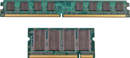
Generally, portable systems have only one or two connectors for additional memory. Older portable systems might use proprietary memory modules, whereas recent systems use SODIMMs (a reduced-size version of a DIMM module).
Tip
The best memory upgrade for a portable system is to add the largest memory module (in MB) that can be installed in the system. Because a future memory upgrade would require the removal of the original memory module on systems with a single memory upgrade socket, it’s best to add all the memory a system can take from the beginning.
Figure 9-1 compares a typical DDR2 SODIMM with a DDR2 DIMM.
Figure 9-1 Comparison of a DIMM (above) and SODIMM (below).
![]()
Storage Devices
Laptop and portable computers use storage devices that vary in several ways from those found in desktop computers:
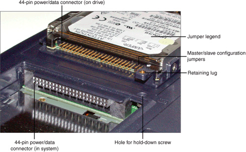
• Smaller form factors— Laptop and portable systems use 2.5-inch or 1.8-inch hard disks, instead of the 3.5-inch hard disks found in desktop computers. Also, laptop and portable systems use slimline optical drives rather than the half-height drives that are used in desktop computers.
• Different implementations of common interfaces— Although laptop and portables with SATA drive support use the same power and data connectors as desktop systems with SATA drives, PATA (ATA/IDE) drives found in laptops and portable systems use a single 44-pin connector for both power and data. Figure 9-2 shows a typical notebook PATA hard drive and interface.
Figure 9-2 A typical 2.5-inch ATA/IDE hard drive for notebook computers and its 44-pin interface.
![]()
Note
You can purchase bare 2.5-inch notebook ATA/IDE or SATA drives to use as replacements for failed or outdated drives, but many vendors sell special kits that include data-transfer software and a data-transfer cable to “clone” the old hard drive’s contents to the new hard drive.
If you plan to reuse the hard disk you replaced, you can also install the old hard disk into an external disk enclosure that connects to your system with USB, IEEE-1394a, or eSATA cables.
Systems that have no internal provision for the type of drive desired can attach an external drive to any of the following:
• USB 2.0 port
• IEEE-1394a port
• eSATA port
• PC Card or ExpressCard with USB, IEEE-1394a, or eSATA port
Peripherals
Low-end laptop and portable computers usually feature limited expandability; if the device can’t connect to one of the ports built into the computer (or to a hub connected to the computer), you can’t use it. However, many mid-range and high-end laptop and portable computers feature various methods for connecting additional devices.
Docking Stations and Port Replicators
A docking station expands the capability of a portable computer by adding features such as
• One or more expansion slots
• Additional I/O ports, such as serial, parallel, PC Card or ExpressCard, VGA, component video, SPDIF digital audio, or USB 2.0
• Additional drive bays
• Connectors for a standard keyboard and mouse
Most docking stations are produced by the vendor of the portable computer and connect to the computer through a proprietary expansion bus on the rear or bottom of the computer. The user can leave desktop-type peripherals connected to the docking station and can access them by connecting the portable computer to the docking station.
Note
Some thin and light portable computers are designed to use a modular media slice for optical and removable-media drives. This unit connects to the bottom of the computer and can be left in place at all times, or it can be removed when it’s not needed.
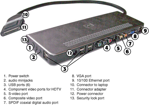
Figure 9-3 shows a typical docking station for an HP or Compaq laptop computer.
Figure 9-3 The HP QuickDock docking station supports several series of HP and Compaq laptop computers.
![]()
To see the expansion port used by the docking station shown in Figure 9-3, refer to Figure 9-12 in this chapter.
A port replicator usually connects to the same proprietary expansion bus that can be used by a docking station; however, many portable computers that do not have docking stations support optional port replicators.
Port replicators don’t have expansion slots or drive bays but replicate the same ports that are found on the host PC. These ports might include VGA, Ethernet network, USB 2.0, and legacy ports (PS/2 mouse, keyboard; serial; parallel).
Port replicators enable a portable computer user fast, easy connection to a full-sized keyboard, regular mouse or pointing device, desktop VGA monitor, modem, and printer without needing to attach or remove multiple cables. Because portable cable connectors can wear out, using a port replicator extends the life of the system and makes desktop use faster and easier.
The difference between a port replicator and a docking station is that the port replicator has the same ports as those found on the laptop computer itself, while a docking station offers additional ports and sometimes other features. For example, the docking station shown in Figure 9-3 adds additional USB 2.0 ports as well as SPDIF coaxial digital audio and component video ports.
Port replicators normally are built by the same company that makes the portable computer, but some third-party vendors produce both dedicated models (designed to attach to the proprietary expansion bus of a given model) and universal versions, which attach through the ExpressCard or PC Card slot or USB port and can be freely moved among different brands and models of portable computers.
Note
Software drivers are required for universal port replicators but not for standard port replicators.
Media and Accessory Bays
Some portable computers have interchangeable drives built into a special media or accessory bay. These drive bays are often able to accommodate the user’s choice of
• Hard disk drive
• Optical drives, such as CD-ROM, CD-RW, DVD-ROM, or rewritable DVD
• Extra batteries
Some older systems might also have support for removable-media drives such as floppy, Zip, or LS-120/240 SuperDisk drives, all of which are now obsolete.
Some models with interchangeable drives allow you to hot-swap, which enables the user to exchange drives without shutting down the computer, whereas others require the user to shut down the system, change drives, and then restart the computer. Portable computers with interchangeable media or accessory bays are more expensive but are also more versatile than portable computers that lack these features.
Expansion Slots
Laptop and portable computers don’t use the PCI, AGP, or PCI Express expansion slots designed for desktop computers. Instead they feature expansion slots especially designed for portable use.
PCMCIA (PC Card, CardBus)
PC Cards (originally referred to as Personal Computer Memory Card International Association [PCMCIA] cards) provide a range of options for portable computers with PC Card slots.
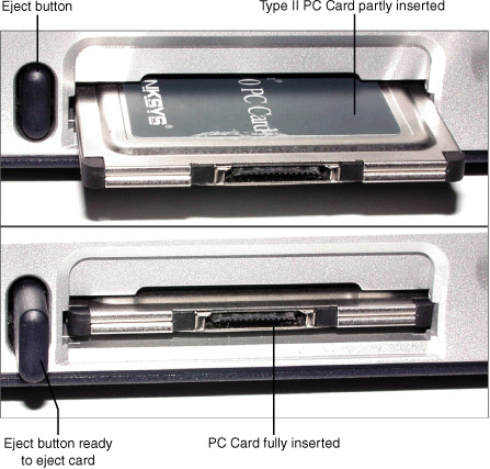
Most portable computers have at least one Type II PC Card slot, as shown in Figure 9-4. Many have two.
Figure 9-4 A typical notebook with a Type II PC Card partly installed (top) and completely installed (bottom). Note the positions of the ejection button.
![]()
PC Cards can be hot-swapped; the card can be shut down, removed, and replaced with another without shutting down the system. Cards must be “stopped” before being removed or the system can become unstable and the cards or system can be damaged. For details, see the section “Safe Removal of PC Cards,” later in this chapter
The Personal Computer Memory Card International Association gave PC Cards their original name of PCMCIA cards and is responsible for developing standards for these cards. There are three types of PC Card slots, each designed for particular types of devices (see Table 9-3).
Table 9-3 PC Card Type Comparison
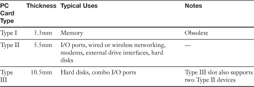
All three types use a two-row connector with 68-pins total.
Most systems with PC Card slots feature two stacked Type II slots that can handle all types of cards: a single Type III card, two Type II cards, or two Type I cards at a time. Figure 9-5 compares the thicknesses of these cards.
Figure 9-5 Typical Type I, Type II, and Type III PC cards and cross-sections.

![]()
Most recent portable systems with PC Card slots support CardBus. CardBus slots are compatible with both ordinary (16-bit) PC Cards and 32-bit CardBus cards, but CardBus cards can’t be used in ordinary PC Card slots.
To verify if a portable system has CardBus support, open Windows Device Manager and the category marked PCMCIA Adapters. If a CardBus controller is listed, the portable supports CardBus. If it’s not listed, you can use only 16-bit PC Cards in that system.
Note
CardBus cards have a gold edge on the connector, but ordinary PC Cards do not. Figure 9-6 illustrates a standard PC Card, and Figure 9-7 illustrates a CardBus card.
Figure 9-6 A typical Type II PC Card 10/100 Ethernet card with the dongle used to attach the card to standard Category 5 UTP cable. Photo courtesy Linksys.
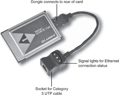
![]()
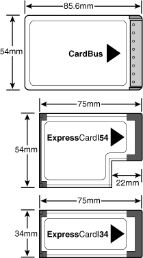
Figure 9-7 A CardBus 32-bit PC Card compared to ExpressCard/34 and ExpressCard/54 cards.
![]()
Another variation on standard PC Card slots is Zoomed Video (ZV) support. Portable systems that support ZV can use PCMCIA cards with a high-speed video connector for processes such as teleconferencing or dual-display support. As with CardBus, use ZV-compatible cards only in compatible systems. However, ZV is not supported by all CardBus slots. To determine if a system with CardBus slots also supports ZV, check with the vendor. Combo PC Cards contain multiple functions and connections on a single card. The most common combination includes a modem plus Ethernet network interfacing or USB 2.0 plus IEEE-1394a interfacing.
Type I and Type II PC Card cards aren’t thick enough to use standard RJ-11 telephone (for modem), SCSI, RJ-45 UTP network cables, or video cables. Some Type II PC Cards use a pop-out connector for telephone or network cables; others require the use of a device called a dongle—a proprietary extension to the PCMCIA card that enables standard cables to be connected to the card. Type III PC Cards are thick enough to provide standard connections but don’t fit into some systems.
Figure 9-6 shows a typical PC Card network adapter with its dongle.
Note
If you lose or damage the dongle, your PC Card is useless until you replace it. For this reason, most vendors no longer use dongles for modem or network cards.
ExpressCard
An increasing number of laptops and portable computers have replaced PC Card slots with ExpressCard slots. The ExpressCard standard is controlled by the same organization that controls the PCMCIA (PC Card) standard, but ExpressCard provides a much faster interface than PC Card or CardBus and is compatible with PCI Express and USB 2.0 standards. ExpressCard is up to 2.5 times faster than CardBus cards, and uses a 26-contact connector.
ExpressCard slots and devices support one of two variations:
• ExpressCard/34 is 34mm wide
• ExpressCard/54 is 54mm wide; ExpressCard/54 slots can use either ExpressCard/54 or ExpressCard/34 devices, and are sometimes referred to as Universal slots
Both types of ExpressCard modules are 75mm long and 5mm high. Figure 9-7 compares typical ExpressCard modules to a CardBus module.
Note
Some vendors supply ExpressCard/34 cards with removable adapters that permit cards to be inserted securely into ExpressCard/54 slots.
ExpressCard can use one of two methods to communicate with the system chipset: PCI Express or USB 2.0. These methods provide much faster performance than with CardBus, which connects to the system chipset via the CardBus controller and the PCI bus.
Note
For more information about ExpressCard slots and devices, see the official ExpressCard website at www.expresscard.org.
Mini-PCI
Most recent notebook computers with built-in modem, Ethernet, or wireless Ethernet (Wi-Fi) support use a reduced-size version of the PCI add-on card standard known as mini-PCI to support some or all of these ports.
There are three major types of mini-PCI cards:
• Type I
• Type II
• Type III
Type I and Type II cards use a 100-pin stacking connector that plugs directly into the system board. Type II cards, unlike Type I cards, have network or modem connectors built into the card. Type III, which uses an edge connector, has become the most popular of the three formats. Like Type I, Type III mini-PCI cards do not incorporate RJ-11 (modem) or RJ-45 (Ethernet network) connectors; Type I and Type III mini-PCI cards use modem and network connectors built into the system.
Although mini-PCI cards can sometimes be replaced in the field, they are not available at retail stores; they must be purchased from the portable computer supplier because they are customized to the characteristics of a particular product family. Mini-PCI cards are used to configure different models of a particular portable computer with different features. Because mini-PCI cards can be replaced, this enables you to replace a failed or outdated network/modem component without replacing the entire motherboard.
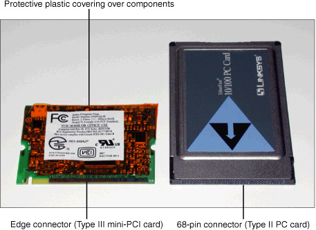
Figure 9-8 shows a typical Type III mini-PCI modem card and connector compared to a typical Type II PC Card.
Figure 9-8 A typical mini-PCI Type III modem (left) compared to a typical PC Card Type II network adapter (right).
Note
Some mini-PCI cards that include wireless Ethernet (Wi-Fi) radios have the antenna leads soldered to the card. If these cards become damaged, a factory-trained technician should replace them.
Communications Connections
Laptop and portable computers usually include some or all of the communications capabilities discussed in the following sections.
Bluetooth
The Bluetooth personal area network (PAN) standard is used for connections with Bluetooth-enabled printers, mice, and keyboards, and for data transfer between computers or PDAs that also include Bluetooth support.
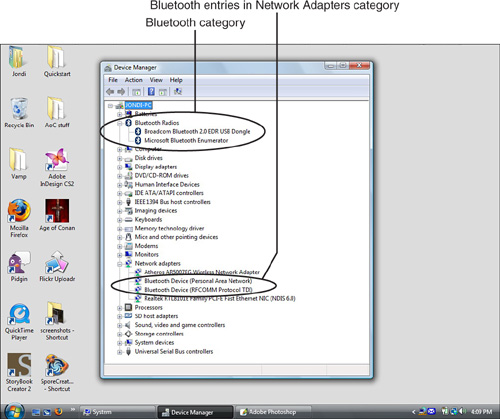
To determine if a computer includes a Bluetooth adapter, you can check its documentation, or examine Device Manager. A computer with a Bluetooth adapter will display a category called Bluetooth Radios and list two Bluetooth entries in the Network Adapters section, as shown in Figure 9-9. You can also add a Bluetooth adapter to an available USB port.
Figure 9-9 The Device Manager for a system offering Bluetooth support has a separate Bluetooth category as well as Bluetooth entries in the Network Adapters category (Windows Vista shown, but Windows XP lists Bluetooth devices the same way).
Infrared (IrDA)
Some portable computers feature an infrared (IR) port. This port usually follows the IrDA standard and can be used for the following tasks if the other device also follows the same standard:
• Networking to connect to computers with compatible IR ports
• Printing to laser and other printers equipped with a compatible IR port
Note
IrDA ports emulate serial ports and provide very slow data transfer compared to USB, Ethernet, Wi-Fi, or other interfaces. IrDA is a suitable choice only if other connection types are not available or not convenient.
Portable computers with integrated IrDA ports have a red window covering the IrDA transceiver on the side or rear of the system and will list an IrDA or IR port in the Ports (COM & LPT) category of Device Manager.
If you add an IrDA port with a USB or other adapter, the IrDA port shows up in a separate Infrared Devices category.
Cellular WAN
Although Wireless Ethernet (WLAN) adapters are very common in recent laptops and portable computers, many users who need to access data networks outside of WLAN coverage area are now using cellular WAN adapters, These adapters, available in ExpressCard, CardBus, and USB 2.0 form factors, permit computers to access high-speed cellular data networks.
A cellular WAN adapter is usually bundled with a data plan from a cellular carrier. However, some laptops now include an integrated cellular WAN adapter. A cellular WAN adapter will be listed in the Modems category of Device Manager and might also be listed in other categories.
Ethernet
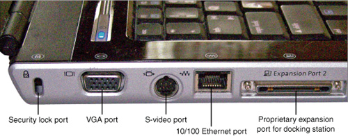
Most laptops and portable devices include an Ethernet port that supports Fast Ethernet (10/100Mbps); some recent models support Gigabit Ethernet (10/100/1000Mbps). Laptops with an integrated Ethernet adapter have an RJ-45 port located on the side or rear of the computer, as shown in Figure 9-10.
Figure 9-10 The Ethernet (RJ-45 port) and other ports on a typical laptop computer.
![]()
You can add Ethernet support to a laptop that doesn’t have an integrated Ethernet port by plugging in a PC Card, CardBus card, or USB adapter with Ethernet support. To see a PC Card with Ethernet support, refer to Figure 9-6.
To determine what level of Ethernet support a particular system includes, open Device Manager’s Network Adapters category and look up information on the network adapter chip model number at the chip vendor’s website.
Wireless Ethernet (WLAN)
Most late-model laptops include wireless Ethernet (WLAN) support, typically implemented through a mini-PCI adapter that incorporates a wireless Ethernet radio that is connected to an antenna built around the LCD display screen.
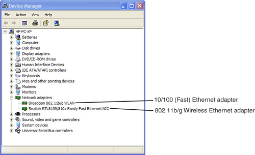
To determine what type of wireless Ethernet a laptop supports, check the documentation, open Device Manager’s Network Adapters category (see Figure 9-11), or examine the markings on the mini-PCI card providing wireless Ethernet support.
Figure 9-11 Typical wireless and wired Ethernet network adapters as listed in Device Manager.
LCD Screen Technologies
One of the biggest differences between portable and desktop computers is the display. Desktop computers enable both the screen and the graphics card to be changed; in portable computers, both the screen and graphics card are normally built into the system (although a few high-end laptops now support removable graphics modules). Although most portables feature an external VGA or DVI port, which enables a separate monitor or video expansion device such as the Matrox Graphics DualHead2Go or TripleHead2Go to be plugged into the computer, that is the extent of the video expandability of most portable systems. Almost all recent systems support DualView, a Windows XP and Vista feature that enables supported graphics chipsets to use an external monitor as a true secondary monitor as well as a mirror of or replacement for the built-in display.
Two major types of LCD display screens have been used on portables: active-matrix and passive matrix.
Active Matrix
Active-matrix refers to screens that use a transistor for every dot seen onscreen: for example, a 1,024×768 active-matrix LCD screen has 786,432 transistors. The additional transistors put the “active” in active-matrix, making them nearly as bright as CRT displays. They also offer wide viewing angles for easier use by groups of people and tend to display rapid movement and full-motion video with less blur than dual-scan displays. Active-matrix displays are used in all levels of laptop and portable computers.
Passive Matrix
Until a few years ago, only high-end laptops and portable computers used active-matrix screens. Mid-range and low-end laptops and portable computers used passive-matrix or dual-scan displays instead. Both are controlled by an array of transistors along the horizontal and vertical edges of the display. For example, a 1,024×768 resolution display features 1,024 transistors along the horizontal edge of the display and 768 transistors along the vertical. The transistors send out a pulse of energy, and the individual LCDs polarize at varying angles to produce the picture. Dual-scan screens split the screen into a top half and a bottom half for faster response.
Passive-matrix LCD displays are dimmer, have slower response times, and feature a narrower viewing angle than active-matrix screens; they are now obsolete.
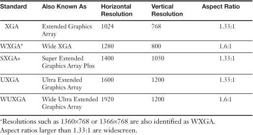
Screen Resolutions
Screen resolutions are identified in one of two ways: either by the number of horizontal and vertical pixels, or by the display standard. Common display standards and pixel resolutions used by recent laptop and portable computers are listed in Table 9-4.
Table 9-4 Common Laptop Screen Resolution Standards
Screen Quality Considerations
When comparing laptops and portable computers, consider the following factors that affect screen quality:
• Contrast Ratio— The difference in brightness between the lightest and darkest portions of the display. When looking at two otherwise-similar displays, the one with the higher contrast ratio is preferred.
• Viewing Angles— The angle at which an LCD display provides acceptable viewing quality. For example, if a display provides acceptable viewing quality at an angle of 80° from either side of a straight on (0°) view, it has a viewing angle of 160° (80°×2). A narrower viewing angle is preferred for privacy (because it’s more difficult for onlookers to view the screen), but a wider viewing angle is preferred when multiple users need to see the display.
• Native and Scaled Resolutions— LCD displays have only one native resolution, and must scale (zoom) the display to achieve lower resolutions. This might be necessary when running the display in a cloned mode when an external display or projector is used, or if a particular resolution is required for creating screen shots or for other technical reasons. Non-native resolutions are selected through the use of the Display properties Settings tab in Windows XP (see Figure 9-12).
Figure 9-12 Selecting native (a) and scaled (b) resolutions on a typical widescreen laptop.
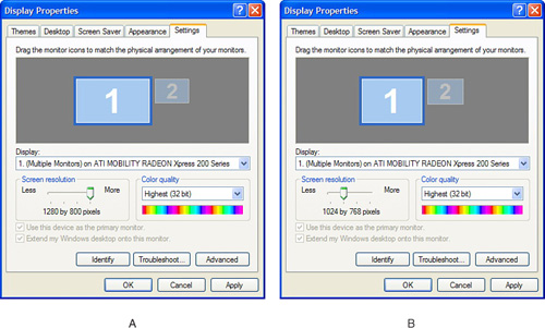
When a scaled resolution is selected, the screen will usually appear slightly less sharp than when the native resolution is selected.
Note
On some very old systems, you might have the option to use only the actual pixels needed for the lower resolution, leaving a black border around the display (“windowboxing”) rather than scaling the display. Use this option (if available) if the scaled screen display has unacceptable quality. To see if this option is available, click the Advanced button available from the Settings tab shown in Figure 9-12 and check the options available.
Tip
To modify video resolution in Windows Vista navigate to Control Panel, Personalization and select Display Settings.
Input Devices
Laptop and portable computers include a variety of specialized input devices, as discussed in the following sections.
Stylus and Digitizer
Portable computers in the tablet form factor use a stylus to enable data entry without using a keyboard. The stylus acts as a digital pen and the touch-sensitive screen digitizes the input from the stylus. Operating systems such as Windows XP Tablet Edition and all versions of Windows Vista support tablets. These operating systems include utilities that support digital ink, conversion of printed text into editable documents, and conversion of drawings made by the stylus into bitmapped graphics.
Convertible systems include a movable screen and a keyboard, enabling the computer to be used either as a tablet or as a traditional portable system.
Fn Keys
To save space, laptops and portable computers use keyboards with fewer keys than desktop computers have. However, laptop and portable computers also need to control screen displays and other options not needed on desktop computers.
To enable reduced-size keyboards to perform all of the functions needed, laptop and portable keyboards use Fn keys. While the Fn key is held down, pressing any key with an additional Fn function performs the Fn function; when the Fn key is released, the key reverts to its normal operation. Fn functions are usually printed below the normal key legend in blue. Figure 9-13 shows a typical portable keyboard with the Fn key and Fn functions highlighted.
Figure 9-13 A typical laptop keyboard’s Fn keys.

![]()
Touch Pad
This mouse alternative uses a square or rectangular touch-sensitive surface located beneath the spacebar (see Figure 9-14). To move the mouse pointer, the user slides his or her finger on the surface. Clicking and double-clicking can be done by tapping on the touch pad surface with the finger or with the touch pad buttons.
Figure 9-14 A laptop that includes both a touch pad and a pointing stick.

![]()
The mouse buttons for the touchpad are also located beneath the spacebar; if the buttons are arranged vertically, the top button corresponds to the left mouse button and the bottom button corresponds to the right mouse button. Some systems might feature an additional button or side-mounted slider for scrolling the screen.
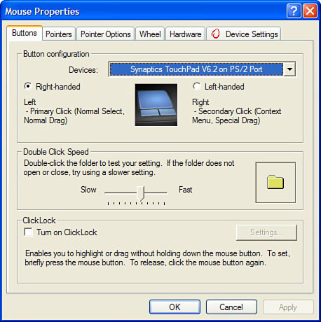
Select the touchpad in the Mouse properties sheet in Windows to configure clicking or other touchpad options (see Figure 9-15).
Figure 9-15 The properties sheet for a typical touch pad.
Pointing Stick / TrackPoint
This mouse alternative (originally called the TrackPoint II by IBM) enables the user to keep his or her hands on the keyboard at all times. The user moves the mouse pointer by pushing a small button shaped like a pencil eraser that’s located in the middle of the keyboard to move the mouse pointer. Although this technology was developed by IBM for its portable computers, it has been licensed by several other vendors, including Toshiba and HP, and it is now found on some laptop computers produced by Lenovo, which purchased IBM’s personal computer division a few years ago. Refer to Figure 9-14 to see an example of a pointing stick on a laptop that also includes a touch pad.
The mouse buttons for a computer equipped with a pointing stick are located beneath the spacebar. Some systems use the conventional left and right buttons, but others use buttons arranged vertically, in which the top button corresponds to the left mouse button and the bottom button corresponds to the right mouse button. Newer systems might feature an additional button used to scroll the screen.
Power Management Issues
Most laptops and portable computers use processors that are designed to draw less power than their desktop counterparts and support power management technologies such as processor throttling, peripheral power management, and others.
Processor Throttling
Processor throttling enables the processor to run at lower clock speeds when processor loads are light and to run at higher clock speeds when processor loads increase. This is a feature of recent processors from both Intel and AMD. Some processors also reduce the front side bus speed during time periods when processor loads are light, a feature Intel calls Front Side Bus Frequency Switching.
Processor throttling might be enabled through the use of a driver that works automatically, such as the AMD Processor Driver or through customized BIOS code.
Peripheral Power Management
Peripherals connected to USB ports or plugged into CardBus or ExpressCard slots can also be configured to go into low-power sleep modes when idle. These options can be configured through the device properties sheet’s Power tab or by adjusting the Power Management settings used in Windows. For details, see “Configuring Power Management,” later in this chapter.
Power Sources
Laptops and portable computers can use battery power or external DC power sources, such as AC adapters, 12V cigarette lighter adapters, or airline power connectors. Battery power is a vital feature for portable computers, which are frequently used when away from an AC power source. Battery life depends on several factors, including
• Battery type
• Recharging practices
• Power-management options
• Memory size
• CPU speed and type
• PC Card or ExpressCard type and use
Battery Types
The rechargeable battery type used by a portable computer has a great deal to do with the amount of time you can use a computer between recharges (the run time).
The most common battery types include
• Nickel-metal hydride (NiMH)
• Nickel-cadmium (NiCd)
The original rechargeable standard, NiCd, has fallen out of favor for use as a notebook computer’s main power source because of a problem called the memory effect. If NiCd batteries are not fully discharged before being recharged, the memory effect enables the battery to be recharged only to the level it was used. In other words, if you use a NiCd battery and recharge it when it’s only 50% exhausted, the memory effect will enable you to use only 50% of the battery’s actual capacity. You might be able to correct the memory effect if you’ll allow your battery to fully discharge before recharging it; however, the memory effect can permanently affect your battery’s condition.
Low-cost notebook computers use NiMH batteries instead of NiCd. NiMH batteries have fewer problems with the memory effect and can be used in place of NiCd in most cases.
The most efficient battery technology in widespread use is Li-ion, which has little problem with memory effect, puts out the same power as NiMH, but is about 35% lighter.
Tip
Battery power is measured in milliampere hours (mAh) or by the number of cells in the battery pack. The larger the mAh value or the larger the number of cells in the battery, the longer the battery will last. If you need to replace the battery in a portable computer, find out if you can get a high-capacity battery instead of the standard capacity battery originally supplied with the computer.
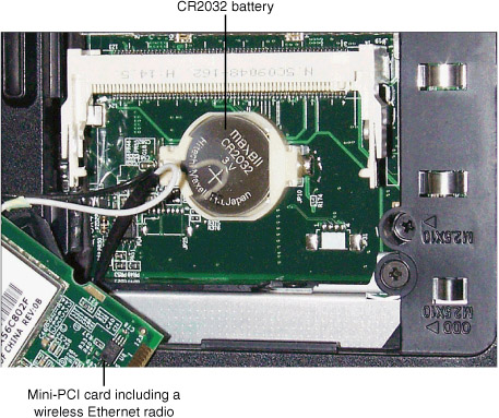
NiCd batteries are sometimes used today as CMOS batteries or as “RAM” or “bridge” batteries, which store a system’s configuration when the suspend mode is used. However, in most recent systems, a lithium watch battery is used to store CMOS settings (see Figure 9-16).
Figure 9-16 A lithium watch battery (CR2032) used to maintain CMOS settings in a typical laptop.
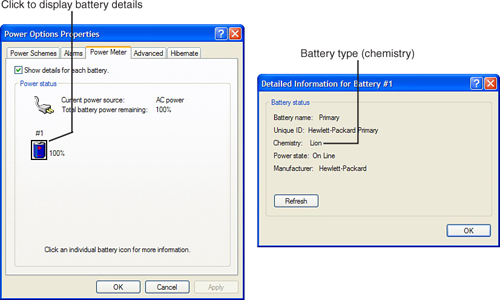
To determine the type of battery installed in a system, open the Power Options properties sheet in Device Manager, click the Power Meter tab shown in Figure 9-17a, and click each battery icon listed. The Detailed Information listing displays the battery type (chemistry) as shown in Figure 9-17b.
Figure 9-17 The Power Meter tab (a) displays battery type and power state for a laptop computer’s primary battery (b) when the battery icon is clicked.
![]()
AC Adapters
Most systems use an external AC adapter and battery-charging unit, sometimes referred to as a brick. To make portable use easier, some systems build the AC adapter/battery charger into the portable computer and use a special polarized power cord for recharging.
Just as with desktop power supplies, notebook battery recharging systems must be compatible with the local electrical power source. Most portable computers use an automatically switching recharger, capable of handling either European and Asian 50-cycle, 230V power or North American 60-cycle, 115V power (see Figure 9-18). However, a few systems are shipped with a single voltage recharger, requiring that you use a power converter or recharger with a different voltage if you travel internationally.
Figure 9-18 A typical laptop AC adapter that can be used with 115V/60-cycle or 230V/50-cycle AC power sources.

Configuring Power Management
Understanding how power management works and how to configure it are essential skills, especially given the increasing number of laptops and portable computers in use today.
ACPI
For several years, all portable and laptop computers have supported the advanced configuration and power interface (ACPI) standard for power management. ACPI power management provides power management for all plug-and-play devices installed in a system, and it permits Windows to perform all power-management configurations rather than force the user to modify the BIOS setup to make some of the needed changes as with the older advanced power management (APM) standard.
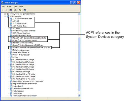
To determine which power management mode the computer is using, open Windows Device Manager and open the System Devices category. On a portable system that uses ACPI power management (Figure 9-19), you will see a number of ACPI system devices.
Figure 9-19 A portable computer with ACPI power management support installed.
Portable systems running Windows XP (and Windows 2000) use the Power Options properties sheet in Control Panel to configure power management. The Power Options properties sheet has five tabs on a system that uses ACPI power management (a sixth tab, for APM power management, is seen only on systems that use APM power management rather than ACPI).
The Power Schemes tab shown in Figure 9-20a is used to control how long the system is idle before the monitor and hard disks are turned off or the system goes into standby or hibernation modes. Note that portable systems have two groups of settings: one for AC power (plugged in) and one for battery power.
Figure 9-20 The Power Schemes tab (a) and Alarms tab (b) of the Power Options properties sheet.

![]()
The Alarms tab shown in Figure 9-20b is used to configure user alerts and automatic actions to take when the system reaches low or critical battery power levels.
For details on the Power Meter tab, refer to the section “Battery Types,” earlier in this chapter.
The Advanced tab (Figure 9-21a) configures actions the computer will perform when the lid is closed or the power or sleep buttons are pressed. The Hibernate tab (Figure 9-21b) enables or disables hibernation and displays the amount of disk space the hibernation file (hiberfil.sys) will occupy.
Figure 9-21 The Advanced tab (a) and Hibernate tab (b) of the Power Options properties sheet.

![]()
Power options on portable systems running Windows Vista can be modified by going to the Control Panel, selecting Classic view, and double-clicking the Power Options applet. By default in Vista, there are three preferred plans: Balanced, power saver, and high performance; however, users can create their own power plans as well. Each of these plans can be modified by clicking the Change Plan Settings link. There are a lot of settings in this window, let’s show one example.
In Balanced, click Change Plan Settings. The display is set to turn off in 20 minutes by default; it can be set from 1 minute to 5 hours, or set to never. If you click the Change Advanced Power Settings link, the Power Options button will appear. Click it to open the Advanced Settings dialog shown in Figure 9-22.
Figure 9-22 The Advanced tab in Windows Vista’s Power Options dialog.
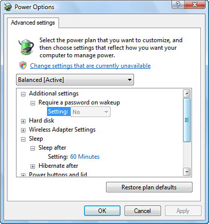
In this dialog, you can specify how long before the hard disk turns off, and set power savings for devices such as the processor, wireless, USB, and PCI Express.
To configure alarms in Vista go to the Battery area, and find the Low Battery notification. Take a few minutes to look through these options and the options for the other power plans.
Suspend, Standby, and Hibernate Modes
Windows Vista, XP, and 2000 support two different power-saving modes, stand by (also known as “standby” or “sleep”) and hibernate. How do these settings vary from each other, and from normal computer operation?
In stand by mode, the computer stays on, but uses very little power.
Most recent laptops and portables support the S3 sleep state, which saves open programs, windows, and files to RAM (S3 is also known as “suspend to RAM”). When you press a key or move the mouse, the system wakes up from S3 sleep and all programs, windows, and files are as they were when the system went into sleep mode.
To use S3, your system must have S3 support in the BIOS. If the system doesn’t support S3, which can use less than five watts of power, it will use S1 or S2 modes, which save some power, but not nearly as much as S3. As with S3 sleep, use the mouse or keyboard to wake up a system from S1 or S2 sleep.
In hibernate mode (also known as S4 sleep state), the computer creates a file called hiberfil.sys and then shuts down. Hiberfil.sys stores the system’s current state, so when you wake up the system, the same programs and files are open as when you shut down the system. To wake up a system that is in hibernate mode, press the power button. By default hibernation is disabled. To turn it on in Windows XP click the Hibernate tab in Power Options and then check Enable Hibernation. To turn it on in Windows Vista, open the Command Prompt as an administrator. Then type powercfg.exe/hibernate on; it will then show up in the shut down area of the Start menu. To turn it off, type powercfg.exe/hibernate off.
Note
To determine which sleep modes a portable or desktop system supports, download the free (for personal use) Sleeper program from PassMark (www.passmark.com/products/sleeper.htm; licensed versions are available for organizations). Sleeper can be used in a GUI or command-line mode to test your system to determine supported sleep modes, and can also be used to put a system into a specified sleep mode for either a specified amount of time or until the user decides to wake the system.
Stand by or hibernate are two of the options available when configuring the Power Buttons section of the Advanced tab in Power Options, and the system can go into these modes automatically after being idle for a specified period.
To select stand by or hibernate from the Shut Down menu in Windows XP, follow these steps:
Step 1. Click Start.
Step 2. Click Shut Down Computer.
Step 3. To send the system into standby mode, click Stand By. To send the system into hibernate mode, press the shift key to toggle Hibernate in place of Stand By, and click Hibernate.
To select stand by or hibernate from the Shut Down menu in Windows Vista, follow these steps:
Step 1. Click Start.
Step 2. Click the general arrow to the right of the padlock.
Step 3. To send the system into standby mode, click Sleep. To send the system into hibernate mode, click Hibernate.
Applications for Portable and Laptop Hardware
While portable and laptop systems can perform the same tasks as desktop computers, their ability to work away from the office, on AC or battery power, and to be used for presentations distinguish them from their desktop counterparts, as discussed in the following sections.
Using Communications Connections
Portables and laptops can use a variety of communications and network connections, as described in the following sections.
Using Bluetooth
Windows XP SP2 and later include Bluetooth support. The Bluetooth Devices applet in Control Panel is used to add or remove Bluetooth devices, view device properties, change Bluetooth options, or add a COM port.
The properties for a Bluetooth device include the device type, the hardware address of the Bluetooth adapter, the date and time of the last connection, and whether a passkey is used to pair the device to your system.
To control whether Bluetooth devices can connect to your computer, or to be alerted when a new Bluetooth device wants to connect to your computer, use the Options tab.
When Bluetooth computers connect to each other in a personal area network (PAN), at least one of the computers must have discovery turned on. You can join a PAN from the Bluetooth taskbar icon menu, the Bluetooth Network Connection in Network Tasks, or by using View Bluetooth Network Devices from the Network Tasks pane. Each Bluetooth item in a PAN is assigned a unique IP address using automatic private IP addressing (APIPA), which assigns IP addresses in the 169.254.x.x range.
If you use programs that require the Bluetooth device to be assigned a COM port number, use the port configuration option to select a COM port. Bluetooth printers are automatically assigned a virtual printer port after being configured with the Add a Printer option in the Control Panel Printers and Faxes area.
To add a device, run the Add Bluetooth Device Wizard after starting the bthprops.cpl application from the Start menu’s Run command. You can also use this wizard to generate a passkey, which creates a more secure connection between devices.
The fsquirt.exe program is used to perform file transfers (send or receive) between computers or computers and other devices using Bluetooth. The telephon.cpl program is used to configure Bluetooth devices that support dial-up networking as modems.
For more information on using Bluetooth with Windows XP SP2 and newer versions of Windows, see http://support.microsoft.com/kb/883259.
Using Infrared (IrDA)
To assure that IrDA devices such as printers can be recognized by PnP detection, make sure the IrDA port built into (or connected to) your system is properly configured before installing a printer. Note that IrDA relies on line-of-sight connections between computers and devices.
If Windows detects an IrDA printer during printer installation, it automatically sets up the correct port type. To print to the printer, just start the print job and Windows will send the print job via the IrDA port.
IrDA ports are assigned COM port numbers, so if you want to use an IrDA port for file transfer, you must configure your file transfer program to use the appropriate COM port. Use Windows Device Manager to determine this information.
Using Cellular WAN
A cellular WAN card typically contains a SIM card, just as a digital cell phone does. Before you can connect to a mobile network with a cellular WAN card, you must activate the SIM card it contains. Use the utility provided by the mobile network provider.
Use the mobile network provider’s utility to make the connection to the cellular network. Once a connection is made to the network, users can browse the Web, send or receive email, perform file transfers, or other activities just as with a wired or wireless Ethernet connection.
Using Ethernet
To use an Ethernet connection in a laptop or portable computer, connect a network cable on a working network to the RJ-45 port on the laptop.
If the laptop is configured to receive an IP address and DNS servers automatically and a server on the network provides this information, the network can be used immediately. If the laptop is connected to a network that requires that this information be entered manually, enter the correct values into the configuration for the network port. For details, see “Networking Configuration,” in Chapter 16, “Networking.”
Using Wireless Ethernet (WLAN)
The methods used for connecting to a wireless network with Windows vary with the version of Windows used and with the configuration of the network. Windows 2000 does not include a built-in wireless Ethernet client; you must use a client provided by the wireless adapter vendor.
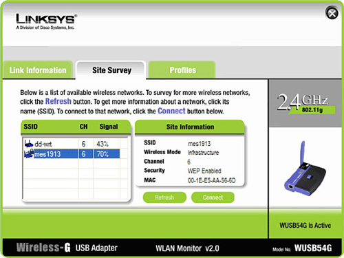
To connect to a wireless network using a vendor-provided client and Windows, you need to know the wireless network’s SSID, the type of encryption used (WPA, WPA2, WEP, or open), the channel number, the type of connection (ad-hoc or infrastructure), and the encryption key. If the network uses WEP encryption, you must also know the length of the encryption key used: 64-bit, 128-bit, or 256-bit. Enter this information as prompted by the vendor-supplied client. Figure 9-23 illustrates a Linksys wireless client.
Figure 9-23 Connecting to a wireless network using a Linksys wireless client.
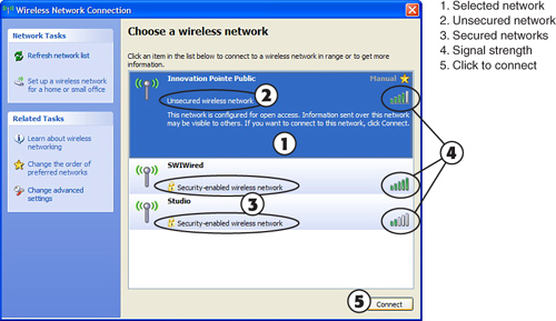
If the system uses Windows XP or Vista and the network is an open (unencrypted) network, Windows can automatically detect the network and start a connection, using Windows’s Wireless Zero Configuration service (see Figure 9-24).
Figure 9-24 Connecting to a wireless network with Windows XP.
![]()
If the network uses WPA, WPA2, or WEP encryption, Windows prompts the user to provide the correct encryption type and encryption key. If the wireless network does not broadcast its SSID, you must manually enter the SSID and other information, either when prompted, or by using the properties sheet for the connection in the Wireless Networks Connection dialog shown in Figure 9-25.
Figure 9-25 Configuring a secured wireless network connection in Windows XP.

![]()
For more information about wireless security and other configuration settings, see “Wireless Ethernet (WLAN) Configuration,” in Chapter 16.
Working with Power Sources
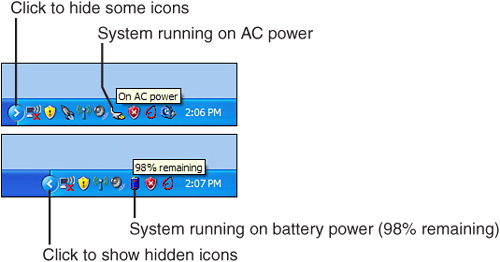
Laptops and portables use AC power when it’s available, and they automatically switch to battery power when AC power is not available. To determine the type of power in use and to determine battery state or charge level, hover the mouse over the power icon in the notification area. Figure 9-26 shows typical messages.
Figure 9-26 AC and battery status messages as displayed by Windows XP’s notification area.
Tip
If the AC or battery status icons or other icons you need to see in the notification area are not visible, click the Show Hidden Icons left arrow. To hide some icons, click the right arrow. Refer to Figure 9-26.
Working with Display Subsystem Components
Although very few laptops offer upgradeable graphics, there are several ways to adjust how the display subsystem works, including adjusting the amount of system RAM set aside for use by integrated graphics, adjusting brightness and contrast on the internal display, and configuring a secondary monitor to act as either an extended desktop or a clone of the internal display.
Adjusting the Amount of Shared Video Memory
Some systems with integrated graphics (graphics built into the system chipset) can adjust the amount of system RAM used for graphics through the BIOS setup program. Increasing the amount of RAM used for graphics can improve 3D rendering and gaming performance, while decreasing the amount of RAM used for graphics provides more memory for Windows when 3D rendering or gaming is not important. To make this adjustment on a typical laptop running Windows XP, follow these steps:
Step 1. Save all open files.
Step 2. Click Start, Turn off Computer, and Restart.
Step 3. When the system restarts, press the appropriate key to run the setup program (see system documentation or an onscreen prompt for details).
Step 4. Locate the Shared Video Memory dialog in the BIOS setup program and select the amount of memory (see Figure 9-27).
Figure 9-27 Viewing options for shared video memory size in a typical laptop with integrated graphics.

Step 5. Save the changes and exit the BIOS setup program. The new amount of video memory will take effect immediately.
Adjusting Brightness and Contrast on a Laptop Computer’s Display
Depending upon the specific graphics solution installed in a laptop computer, there might be more than one way to adjust brightness and contrast. Virtually all laptop computers provide Fn key adjustments for display brightness, and some might also offer contrast adjustments as well. Refer to the keyboard shown in Figure 9-13.
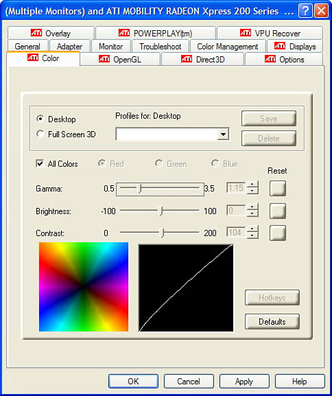
Some systems also provide a proprietary brightness, contrast, and gamma adjustment on the Advanced portion of the display properties sheet (see Figure 9-28).
Figure 9-28 Adjusting brightness, contrast, and gamma with the Color tab provided as part of the ATI Mobility Radeon Xpress 200 display driver’s Advanced properties sheet.
Note
Gamma is the way that brightness is distributed across the spectrum from lightest to darkest tones on a display, scanner, or printer. By adjusting the gamma, you can adjust how midtones are displayed.
Using DualView to Work with a Secondary Monitor or Projector
Windows XP supports DualView with virtually all recent laptop display hardware. DualView enables a secondary display that is plugged into a laptop’s external video ports, such as TV-out, S-video, VGA, or DVI, to be used to extend the desktop; it can also be used to mirror the desktop if desired.
To enable this feature, follow these steps:
Step 1. Before turning on the computer, plug the appropriate video cable into the video port.
Step 2. Turn on the external monitor, TV, or projector.
Step 3. Turn on the computer.
Step 4. If the computer does not automatically extend the desktop, right-click an empty area on the desktop and select Properties, or open Control Panel and open the Display properties icon.
Step 5. Click the Settings tab on the Display properties icon (see Figure 9-29a).
Figure 9-29 The settings dialog before (a) and after (b) enabling a secondary display as an extended desktop.
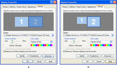
Step 6. To enable the secondary display, click it, and select Extend My Windows Desktop Onto This Monitor.
Step 7. Adjust the screen resolution as needed for the second display (see Figure 9-29b). To determine usable resolutions, check the documentation for the display.
Step 8. Click Apply and then OK to use the settings.
Cloning the Laptop Display to a Secondary Display or Projector
If you need to display the same information on an external display or projector, such as for a presentation, follow this procedure:
Step 1. Determine the resolution of the secondary display or projector. Most projectors offer resolutions such as 800×600 or 1024×768.
Step 2. Use the Settings tab on the Display properties sheet to adjust the resolution of the laptop’s internal display to match the secondary display or projector’s resolution.
Step 3. Do not extend the desktop to the secondary display. Instead, locate the Fn key combination on the keyboard that toggles the display into clone mode. Typically, you must press this key combination several times to move through different display combinations until the displays are cloned. Wait a few moments after you press the key combination to allow the display mode to change before continuing.
Note
Some laptops use a proprietary display-management program to clone the displays. Access it by right-clicking an empty portion of the desktop and selecting it from the menu.
Safe Removal of Laptop-Specific Hardware
Understanding how to safely remove (and install) laptop-specific hardware is an important part of the A+ Certification exams. Although some types of hardware, such as PC Cards and ExpressCard cards, might be removed and installed on a daily basis, other types of hardware are removed and installed only when an upgrade or equipment failure takes place.
Note
The following sections provide basic instructions for removing hardware. For specific information for a particular model, see the service manual or guide provided by the laptop vendor.
The Laptop Repair 101 website (www.laptoprepair101.com) provides many useful resources, including links to major vendors’ laptop service manuals (www.laptoprepair101.com/laptop/category/laptop-service-manual/) and illustrated step-by-step procedures for the removal of many components.
Safe Removal of PC Cards
To remove a PC Card, follow these steps:
Step 1. Look for an ejector button next to the PC Card slot; on some systems, the button is folded into the unit for storage. Unfold the button.
Step 2. Disconnect any cables or dongles from the card.
Step 3. Right-click the Safely Remove Hardware icon in the Windows taskbar and select the card you want to remove from the list of cards.
Step 4. Click Stop and wait for the system to acknowledge the card can be removed.
Step 5. Click OK to close the message.
Step 6. Push in the ejector button to eject the PC Card (refer to Figure 9-4 earlier in this chapter). Pull the PC Card the rest of the way out of the slot and store it in its original case or an antistatic bag.
Safe Removal of ExpressCards
To remove an ExpressCard, follow these steps:
Step 1. Disconnect any cables or dongles from the card.
Step 2. Right-click the Safely Remove Hardware icon in the Windows taskbar and select the card you want to remove from the list of cards.
Step 3. Click Stop and wait for the system to acknowledge the card can be removed.
Step 4. Click OK to close the message.
Step 5. Push in the card to release it. Pull the ExpressCard the rest of the way out of the slot and store it in its original case or an antistatic bag.
Note
Some systems with ExpressCard slots use the slot to store a media remote control. If a remote control is stored in the ExpressCard slot, go directly to Step 5 to remove it.
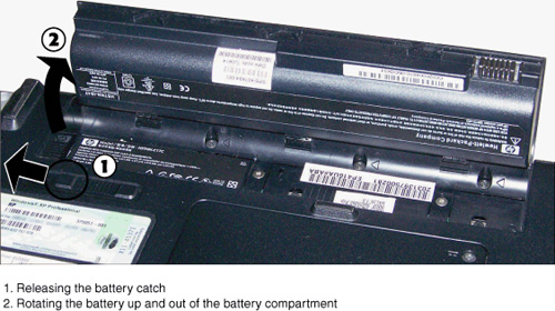
Safe Removal of Batteries
Follow this procedure to replace computer batteries:
Step 1. Turn off the computer.
Step 2. Unplug the AC adapter or line cord from the computer.
Step 3. Locate the battery compartment in the unit; it might be secured by a sliding lock or by screws.
Step 4. If the battery is under a removable cover, remove the battery compartment cover.
Step 5. Release the lock that holds the battery in place.
Step 6. Slide or lift out the battery (see Figure 9-30). If the battery is a flat assembly, it might be held in place by a clip; push the clip to one side to release the battery.
Figure 9-30 Removing a battery from a typical laptop computer.
![]()
Step 7. Check the battery contacts inside the computer for dirt or corrosion, and clean dirty contacts with a soft cloth.
Step 8. Insert the replacement battery. Make sure you insert the battery so the positive and negative terminals are in the right directions.
Step 9. Close the cover and secure it.
Step 10. If the battery must be charged before use, plug in the line cord or AC adapter into both the computer and wall outlet. Check the computer’s manual for the proper charge time for a new battery.
Step 11. Unplug the system or AC adapter when the battery has been charged for the recommended time period.
Caution
Take precautions against ESD when you change the battery. Discharge any static electricity in your body by touching a metal object before you open the battery compartment, and don’t touch the contacts on the battery or the contacts in the battery compartment with your hands.
Safe Removal and Installation of Mini-PCI Cards
To remove a Type III mini-PCI card, follow this procedure:
Step 1. Turn off the computer.
Step 2. Unplug the computer and remove the battery pack.
Step 3. Locate the mini-PCI card in the unit. It might be accessible from the bottom of the system (see Figure 9-31 for an example), or you might need to remove the keyboard or other components.
Figure 9-31 Removing a mini-PCI card from a typical notebook computer.
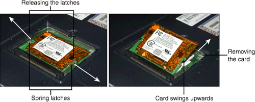
Step 4. Remove the cover or other components over the card.
Step 5. Release the spring latches that hold the card in place.
Step 6. Lift the top of the card up until the card is released from the socket.
To install a mini-PCI card, follow these steps
Step 1. Push the mini-PCI card edge connector into place.
Step 2. Push the top of the card down into the socket until the spring clips lock into place.
Step 3. Replace the cover or other components you removed to gain access to the card socket.
Step 4. Reinstall the battery.
Step 5. Plug the computer in.
Step 6. Start the computer. Install any additional drivers required.
Note
If the mini-PCI card is used for wireless Ethernet, it might be necessary to remove antenna cables from the card before removing it. See the laptop vendor’s service manual for details.
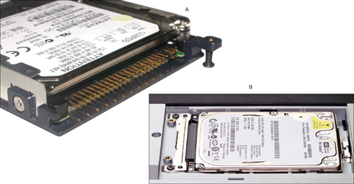
Safe Removal and Installation of Hard Disk Drives
Although a few laptop computers require you to remove the keyboard to access the hard disk, most laptops feature hard disks that can be accessed from the bottom of the system. Follow this procedure to remove and replace a hard disk:
Step 1. Turn off the laptop and unplug it from AC power.
Step 2. Remove the battery (refer to Figure 9.30).
Step 3. Loosen or remove the screw or screws used to hold the drive cover in place.
Step 4. Push the cover away from the retaining lug or clips and remove it. On some systems, the drive might be mounted to the cover (Figure 9-32a), while on other systems, the drive is mounted to the chassis (Figure 9-32b).
Figure 9-32 A laptop hard disk that fastens to the cover (a) compared to one that fastens to a separate frame inside the chassis (b).
![]()
Step 5. If the drive is fastened to the chassis, as in Figure 9-32b, remove the screws holding the drive to the chassis.
Step 6. Push the drive away from the retaining screw holes and lift it out of the chassis.
Step 7. Remove the screws fastening the drive to the drive cover or frame (see Figure 9-33).
Figure 9-33 Removing the hard disk mounting screws from the cover (a) or the frame (b).
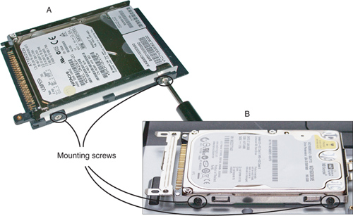
Step 8. Remove the drive from the drive cover or frame.
Step 9. Place the new hard disk into the drive cover or frame.
Step 10. Replace the screws to hold the drive in place.
Step 11. Insert the drive back into the chassis. If the drive is fastened to the cover, replace the cover screw.
Step 12. Replace the chassis screws to fasten the drive back into place.
Step 13. Replace the cover.
Step 14. Replace the battery.
Step 15. Plug the system into AC power.
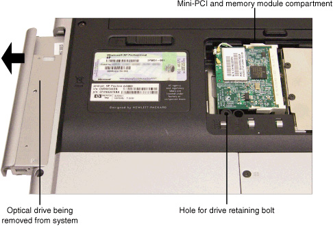
Safe Removal of Optical Drives
Some laptops feature modular optical drives that are designed for swapping. However, if the optical drive is not designed for swapping, follow this procedure to remove it:
Step 1. Locate the mounting screw that holds the drive in place and unscrew it. It might be located inside the access panel for another component, such as the mini-PCI board or memory modules
Step 2. Pull the drive out of the system. See Figure 9-34 for a typical example.
Figure 9-34 Removing an optical drive from a typical laptop.
Safe Removal and Installation of Memory
Memory upgrades often can be performed without removing the keyboard, which covers most other internal components. Follow these steps to perform a typical memory upgrade:
Step 1. Remove the cover over the memory upgrade socket on the bottom of the system.
Step 2. Remove any screws or hold-down devices.
Step 3. Remove the old memory upgrade if necessary.
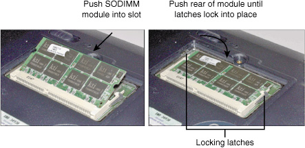
Step 4. Insert the new memory upgrade, making sure the contacts (on the back side or edge of the module) make a firm connection with the connector.
Step 5. If you are installing an SODIMM or small-outline Rambus module, push the top of the module down until the latches lock into place (see Figure 9-35).
Figure 9-35 Installing an SODIMM module on a typical portable computer.
![]()
Step 6. If the memory socket uses screws to secure the memory in place, install them.
Step 7. Test the module by starting the system and observing the memory counter; use third-party diagnostics if possible.
Step 8. Close the cover and secure it to complete the upgrade.
Safe Removal of LCD Panels
LCD display panels built into portable computers are customized for each model of portable computer and require the disassembly of the computer for removal and replacement. You can get replacements from either the vendor or an authorized repair parts depot. Many vendors require that you be an authorized technician before you remove or replace LCD display panels in portable computers. However, the process of replacing the entire LCD display assembly is simpler and might be possible for you to perform in the field.
Caution
Should you do your own LCD display panel replacement? Vendors are of two minds about this. Some vendors provide online documentation that guides you through the entire process of reducing an intact portable into a pile of parts and rebuilding it. However, this information is primarily intended for professional computer service staff. Portables require specialized tools to deal with their tiny screws and snap-together cases and they contain proprietary parts. If you break an internal drive or an integrated keyboard, you can’t run to your favorite electronics superstore for a replacement. You have been warned.
The details of the process for removing an LCD display assembly from a portable computer vary by model, but you can follow these basic steps:
Step 1. If the system has an integrated wireless Ethernet adapter, disconnect the antenna leads coming from the display from the adapter (usually a mini-PCI card).
Step 2. Remove the keyboard frame and keyboard.
Step 3. Disconnect the FPC cable from the system board (also known as the display cable); this cable transmits power and data to the LCD display assembly.
Step 4. If the system has an integrated wireless Ethernet adapter, remove the antenna leads from the clips in the top cover.
Step 5. Rotate the display assembly to a 90-degree angle to the base unit.
Step 6. Remove the screws that secure the display assembly.
Step 7. Lift the display assembly free from the base unit.
Step 8. Be sure to save all screws, ground springs, and other hardware that you removed during the disassembly process.
Depending on the vendor, you might be able to purchase a replacement LCD display assembly that can be installed by following the previous steps in reverse order, or you might need to disassemble the display assembly to remove and install the LCD display panel itself. Replacing the LCD display panel (which requires the disassembly of the display assembly) should be performed at a repair depot.
Because of differences in chipsets, BIOSs, and display circuitry between systems with passive matrix (including dual-scan) and active-matrix LCD panels, dual-scan and active-matrix LCD panels are generally not interchangeable. However, you might be able to swap a reduced-glare display assembly or panel for a brighter panel with more glare, or vice-versa.
Safe Removal and Replacement of Pointing Devices
There are two main types of integrated pointing devices used in laptops and portable computers: touchpads and pointing sticks. Touchpads are generally located in the palm rest (which extends below the keyboard), while pointing sticks such as the IBM/Lenovo TrackPoint and Toshiba AccuPoint are located in the middle of the keyboard (the buttons are located in the palm rest).
If you need to replace the pointing device built into the palm rest (including buttons used by pointing sticks), you need to partially disassemble the portable computer. Details vary from unit to unit (check with your vendor for details), but the basic procedure is described here.
To remove the palm rest, follow these steps:
Step 1. Remove the display panel assembly (if necessary) and keyboard.
Step 2. Turn over the system.
Step 3. Release the clips or screws holding the palm rest in place.
Step 4. Turn the system right side up.
Step 5. Remove the palm rest from the system.
To remove a pointing device, such as a touchpad or others, from the palm rest
Step 1. Disconnect or unscrew the pointing device from the touchpad.
Step 2. Remove the pointing device from the touchpad.
Step 3. You might need to remove the pointing device cable from the pointing device or from the system board; check the specific instructions for the device.
To replace the pointing device, follow these steps in reverse order to install a new pointing device into the palm rest and to reinstall the palm rest into the portable computer.
To replace the pointing stick, it is necessary to remove and replace the keyboard that contains the pointing stick. Details vary from unit to unit (check with your vendor for the details of the particular model you are repairing), but the following is the basic procedure:
Step 1. Remove the display assembly if the vendor recommends it; some portable systems don’t require this step.
Step 2. Remove screws or bezels that hold the keyboard in place.
Step 3. Lift up the keyboard to expose the keyboard cable.
Step 4. Remove any hold-down devices used to hold the keyboard cable in place.
Step 5. Disconnect the keyboard cable from the system board.
Step 6. Remove the keyboard.
Tip
If you have purchased a replacement integrated keyboard, it might include detailed disassembly/reassembly instructions. Contact the parts or system vendor to get this information if your replacement keyboard didn’t include this information.
Portable and Laptop Diagnostics
With more portables and laptops being sold these days than desktops, it’s more important than ever to understand how to diagnose them. The following sections help prepare you for questions you might encounter on the A+ Certification exams as well as in your day-to-day work.
Power Troubleshooting
Portables and laptops can get power from two sources: AC power (wall outlet) and DC power (internal battery).
AC Power Troubleshooting
To verify that the laptop is receiving AC power, check the following:
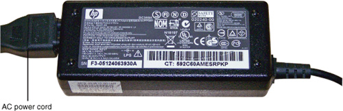
• Make sure the laptop is plugged into a working AC outlet. Check the outlet with an outlet tester. Use a voltmeter or a multimeter set to AC voltage to determine if the output is within acceptable limits.
• Make sure the AC power cord running from the AC outlet to the external AC adapter “power brick” shown in Figure 9-36 is plugged completely into the outlet and the adapter. If the power cord or plug is damaged, replace the cord.
Figure 9-36 A typical laptop “power brick” AC adapter.
• To determine if the adapter is outputting the correct DC voltage, use a voltmeter or multimeter set to DC voltage to test the voltage coming from the adapter and compare it to the nominal output values marked on the adapter. As Figure 9-37 illustrates, it might be necessary to use a bent paperclip to enable an accurate voltage reading. A value of +/− 5% is acceptable.
Figure 9-37 Checking the output voltage from a laptop’s AC adapter.

DC Power Troubleshooting
If the system works when plugged into AC power, but not on battery power, check the following:
• Make sure that the battery is installed properly.
• Determine whether the battery can hold a charge. Make sure the battery is properly installed and the AC adapter has proper DC voltage output levels. Leave the system plugged in for the recommended amount of time needed to charge the battery, then try to run the system on battery power. If the battery cannot run the system at all, or the system runs out of battery power in less than an hour, replace the battery.
• If the battery is hot after being charged or has a warped exterior, it might have an internal short. Replace it.
Display Troubleshooting
When a laptop or portable computer’s built-in display stops working, there are a variety of possible causes. Use the material in this section to troubleshoot the display subsystem.
Using an External Monitor to Check the Display Subsystem
To determine whether the problem with the display subsystem is limited to the LCD display or affects the video circuit itself, connect an external monitor to the system and see if you can perform the following:
• Extend the desktop
• Toggle between internal and external displays using Fn keys
If the external display works then you know that the problem is limited to the integrated LCD display. However, if neither the integrated nor the external display works, the problem is with the discrete graphics chip or the motherboard.
Solving Internal Display Problems
If the internal display fails displaying a white picture, but the external monitor works properly, the connector between the display and the motherboard might be loose. Follow the instructions for removing the LCD display subsystem to access the connector and reattach it. For more details, see “Safe Removal of LCD Panels,” in this chapter. If part of the display is white at all times, the LCD is cracked and you should replace it.
LCD Cutoff Switch
The LCD cutoff switch is used to turn off the bulb that lights an LCD. This is normally enabled on a laptop when the lid is closed. The switch is usually found inside the display; if it fails, the display needs to be opened to repair or replace it. Some laptops have an LCD cutoff button that enables a user to turn off the LCD (bulb) manually.
Note
If you are servicing an old laptop with a monochrome screen, note that damaged areas of the screen might be black rather than white.
Checking for Backlight Problems
If the backlight fails, the screen might appear to have failed entirely. Before you assume the screen has failed, look closely at the screen to see if you can make out items on the display, such as the boot dialog or the Windows desktop. If you can see items on the screen, but the screen is very dark, the backlight has probably failed.
Tip
To help you determine what should be on-screen, connect an external display and press the appropriate Fn keys to switch the display into cloned mode.
Although it’s possible to replace the backlight yourself if you are very careful, this type of repair requires that the display assembly be disassembled.
Caution
Backlights typically are fluorescent tubes and contain mercury. Because mercury is a hazardous chemical that should not be put into a landfill, some laptop service manuals discuss the removal of the backlight in the recycling section.
Dead Pixels
LCD displays can suffer from dead pixels; a dead pixel won’t light up or displays only red, green, or blue light at all times. Laptop manufacturers have varying policies on the number and location of dead pixels a display must have before the laptop can be returned for service during the limited warranty period. If you notice one or more dead pixels, consult the laptop manufacturer for your options.
Tip
In some cases, gently tapping your finger on the screen over the dead pixel can correct the problem.
Other Components
To solve problems with other peripherals, such as the stylus and digitizer, keypad, and wireless Ethernet antenna wires, you need to know the following:
• Where the components are located
• How to disassemble your laptop, troubleshoot it, and reassemble it
Removing Peripherals
The following items can usually be removed by accessing them through the bottom of the laptop or portable computer:
• Memory
• Mini-PCI card (network, wireless network)
• Hard disk
• Optical drive
If any of these components stop working, follow this general procedure:
Step 1. Open Device Manager and delete the item from the listing.
Step 2. Reinstall the item’s driver by clicking Action, Scan for Hardware Changes.
Step 3. After Device Manager reinstalls the device and its drivers, try the device again.
Step 4. If the device continues to fail, shut down Windows, physically remove the device and check it for obvious problems (physical damage, burnt chips, cut wires, warping, and so on).
Step 5. If you don’t see any physical damage to the device, reinstall it and restart Windows.
Step 6. Use the device again. If it continues to fail, replace the item.
For details, see the section “Safe Removal of Laptop-Specific Hardware,” earlier in this chapter.
Stylus and Digitizer Problems
To solve stylus and digitizer problems, you must determine where the stylus is used and disassemble that area as needed to locate loose connections or to replace defective components:
• If the digitizer pad is located on the keyboard, you must disassemble the keyboard and chassis.
• If the digitizer is a touch-sensitive display, you must disassemble the chassis to locate the connection between the display and the motherboard, or you might need to replace the display assembly.
For details, see the section “Safe Removal of Laptop-Specific Hardware,” earlier in this chapter.
Keypad Problems
To solve keypad and keyboard problems, follow this procedure:
Step 1. Connect a desktop keyboard to the computer. If you connect a PS/2 keyboard, you must shut down the laptop or portable computer first. If you connect a USB keyboard, you can do so while the laptop or portable computer is running.
Step 2. Open a program such as Notepad or WordPad and type characters.
Step 3. If you are unable to enter characters using the keyboard, the motherboard has failed and must be replaced. However, if you are able to enter characters using the keyboard, the problem is limited to the keyboard or keypad.
Step 4. Shut down the computer, disconnect it from AC power, and remove the battery.
Step 5. Unplug the keyboard.
Step 6. Disassemble the keyboard and keypad assembly and check the connection.
Step 7. Disconnect the keyboard wire from the motherboard, and then reconnect it.
Step 8. Reassemble the laptop and restart it.
Step 9. Use the laptop’s own keyboard. If it continues to fail, replace the keyboard/keypad subassembly.
Note
See your laptop or portable computer’s service manual for disassembly/reassembly details.
You can order replacement keyboards from your computer’s manufacturer, or you might be available to get them from third-party firms.
Antenna Wires
If Device Manager shows that the wireless Ethernet network adapter in a notebook computer is working properly and other computers can connect to the wireless access point or router, it’s possible that the antenna wires connected to the mini-PCI wireless Ethernet radio card are loose or damaged.
To check the connection between the mini-PCI card and the antenna wires, open the access panel covering the mini-PCI card and verify that the wires are connected to the card—and that the wires are connected to the correct locations on the card. If the card was removed and the wires detached from the card, the wires might be reversed. For details, see the section “Safe Removal of Laptop-Specific Hardware,” earlier in this chapter. If the wires are properly connected, the wireless transceivers built into the display assembly might be damaged. To replace them, you must disassemble the display assembly. See the service manual for your laptop or portable computer for details.
Preventative Maintenance for Laptops and Portable Devices
Preventative maintenance can help prevent failure of laptop and portable computer components. Use the procedures in the following sections to help assure long-term reliable operation.
Cooling Devices
An overheated system might quit, display STOP errors (also known as Blue Screen of Death, or BSOD), or throttle down the processor to very low clock speeds. Overheating can be caused by a blocked cooling fan outlet, cooling fan failure, or damage to the heat sink.
Laptops and portable computers use cooling fans that might be located in the side or bottom of the system. To avoid overheating, make sure the fan outlet is not blocked.
Caution
Using a laptop or portable computer with a bottom-mounted fan on a bed, pillow, or blanket is not recommended because the surface tends to block the fan outlet and can cause the system to overheat.
If the fan outlet or blades are dirty, clean them with compressed air or a brush.
If the fan fails, the fan assembly can be removed and replaced. See the service manual for your system for details.
If the fan is working, but the system is overheating, the heat sink assembly might be damaged, or might not be properly secured to the processor. To determine if either of these problems has occurred, you must disassemble the computer to gain access to the heat sink. A heat sink dissipates heat from the processor to a passive fin assembly that is cooled by the system’s cooling fan.
If the heat sink is loose, the thermal paste or thermal transfer material between the heat sink and the processor needs to be removed and replaced before the heat sink is reattached to the processor. Isopropyl alcohol and a lint-free cotton cloth can be used to remove old thermal paste from the heat sink and processor.
Before reinstalling the heat sink as shown in Figure 9-38, reapply a small amount of thermal paste to the center of the processor’s integrated heat shield and push the heat sink down over the processor to distribute the thermal paste. Then, secure the heat sink.
Figure 9-38 Reattaching the heat sink on a typical laptop or portable computer.

Display Screens
You should clean display screens with anti-static cleaners meant for electronics use, such as Endust for Electronics or similar products. If you use a spray cleaner, spray the cloth or paper towel and use the towel to apply the cleaner.
Suitable Operating Environments
Laptops and portable computers can be operated in a wide range of environments. However, exceeding the recommendations can damage the screen or other components.
Air Temperature
Typical operating range for a laptop is from 50–95°F (10–35°C). Typical non-operating range (for storage and other situations in which the laptop is not in use) is from -4–140°F (-20–60°C). You can find exact values for a particular model in its specifications sheet. Note that batteries discharge more quickly at higher temperatures.
Tip
If a laptop must be operated at temperatures above its operating temperature, use an external fan to help keep the laptop cool. An auxiliary cooling pad that contains its own fans can also help cool the laptop.
Air Quality
Air quality issues are a concern primarily if a laptop or portable computer will be used in an environment that contains a lot of particulates, such as an office that permits smoking, coal mines, grain elevators, and so forth.
To protect the internal parts of the laptop, consider using an air filter over the air intake on the laptop and clean or replace the filter frequently.
Storage Methods
If a laptop or portable computer will be stored for a long period (more than six months), you should remove the rechargeable main battery and the CMOS battery from the computer to prevent leakage and subsequent damage.
The computer should be stored in a water-resistant container, especially if it is located in a flood-prone area or an area protected by sprinkler systems. The original shipping box and plastic protection bag can be used.
Transportation and Shipping
If the original shipping box and protection blocks are not used for transporting the computer, the computer should be placed in a protective bag or sleeve that offers shock protection. You might be able to get a suitable replacement box from the vendor.
Exam Preparation Tasks
Review All the Key Topics
Review the most important topics in the chapter, noted with the key topics icon in the outer margin of the page. Table 9-4 lists a reference of these key topics and the page numbers on which each is found.
Table 9-4 Key Topics for Chapter 9
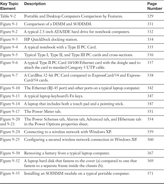
Complete the Tables and Lists from Memory
Print a copy of Appendix B, “Memory Tables,” (found on the CD), or at least the section for this chapter, and complete the tables and lists from memory. Appendix C, “Memory Tables Answer Key,” also on the CD, includes completed tables and lists to check your work.
Definitions of Key Terms
Define the following key terms from this chapter, and check your answers in the glossary.
IrDA,
WLAN,
NiCd,
ACPI,
Troubleshooting Scenario
You have been asked to change out the hard drive in a laptop computer. The laptop is a small compact model. How would you change the hard drive without removing the keyboard?
Refer to Appendix A, “Answers to the ‘Do I Know This Already?’ Quizzes and Troubleshooting Scenarios,” for the answer.