
Chapter 4
Flame phenomena in premixed combustible gases
Abstract
Combustion phenomena in premixed fuel–air mixtures are analyzed including laminar and turbulent flames and stirred reactors. Several theories are reviewed to examine the structure of laminar premixed flames and deduce their laminar flame speeds. The effects of temperature, pressure, equivalence ratio, and mixture diluent are considered. Methods to experimentally measure flame speeds are also discussed. Laminar flame stability characteristics including flammability limits, quenching distance, and flame stabilization are presented and analyzed. The various regimes of turbulent reacting flows are described along with turbulence chemistry interactions and the turbulent flame speed. Stirred reactor theory is introduced, and considerations for flame stabilization, including flashback and blowoff, in high-speed flows are presented. Finally, a brief description of combustion in microsystems is provided.
Keywords
Blowoff; Flame stabilization; Flame structure; Flammability limits; Flashback; Laminar flame speed; Laminar premixed flame; Quenching distance; Stirred reactor; Turbulent flames4.1. Introduction
In the previous chapter, the conditions under which a fuel and oxidizer would undergo explosive reaction were discussed. Such conditions are strongly dependent on the pressure and temperature. Given a premixed fuel-oxidizer system at room temperature and ambient pressure, the mixture is essentially unreactive. However, if an ignition source applied locally raises the temperature substantially, or causes a high concentration of radicals to form, a region of explosive reaction can propagate through the gaseous mixture, provided that the composition of the mixture is within certain limits. These limits, called flammability limits, will be discussed in this chapter. Ignition phenomena will be covered in a later chapter.
When a premixed gaseous fuel-oxidizer mixture within the flammability limits is contained in a long tube, a combustion wave will propagate down the tube if an ignition source is applied at one end. When the tube is opened at both ends, the velocity of the combustion wave falls in the range of 20–200 cm/s. For example, the combustion wave for most hydrocarbon–air mixtures has a velocity of about 40 cm/s. The velocity of this wave is controlled by transport processes, mainly simultaneous heat conduction and diffusion of radicals; thus, it is not surprising to find that the velocities observed are much less than the speed of sound in the unburned gaseous mixture. In this propagating combustion wave, subsequent reaction, after the ignition source is removed, is induced in the layer of gas ahead of the flame front by two mechanisms that are closely analogous to the thermal and chain branching mechanisms discussed in the preceding chapter for static systems [1]. This combustion wave is normally referred to as a flame; since it can be treated as a flow entity, it may also be called a deflagration.
When the tube is closed at one end and ignited there, the propagating wave undergoes a transition from subsonic to supersonic speeds. The supersonic wave is called a detonation. In a detonation, heat conduction and radical diffusion do not control the velocity; rather, the shockwave structure of the developed supersonic wave raises the temperature and pressure substantially to cause explosive reaction and the energy release that sustains the wave propagation.
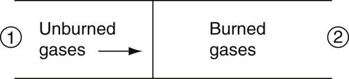
The fact that subsonic and supersonic waves can be obtained under almost the same conditions suggests that more can be learned by regarding the phenomena as overall fluid-mechanical in nature. Consider that the wave propagating in the tube is opposed by the unburned gases flowing at a velocity exactly equal to the wave propagation velocity. The wave then becomes fixed with respect to the containing tube (Figure 4.1). This description of wave phenomena is readily treated analytically by the following integrated conservation equations, where the subscript 1 specifies the unburned gas conditions and subscript 2 the burned gas conditions:
![]() (4.1)
(4.1)
![]() (4.2)
(4.2)
![]() (4.3)
(4.3)
![]() (4.4)
(4.4)
![]() (4.5)
(4.5)
Equation (4.4), which connects the known variables, unburned gas pressure, temperature, and density, is not an independent equation. In the coordinate system chosen, u1 is the velocity fed into the wave and u2 is the velocity coming out of the wave. In the laboratory coordinate system, the velocity ahead of the wave is zero, the wave velocity is u1, and (u1 − u2) is the velocity of the burned gases with respect to the tube. The unknowns in the system are ul, u2, P2, T2, and ρ2. The chemical energy release is q, and the stagnation adiabatic combustion temperature is T2 for u2 = 0. The symbols follow the normal convention.
Notice that there are five unknowns and only four independent equations. Nevertheless, one can proceed by analyzing the equations at hand. Simple algebraic manipulations (detailed in Chapter 5) result in two new equations:
![]() (4.6)
(4.6)
and
 (4.7)
(4.7)
where γ is the ratio of specific heats and M, the Mach number of the wave, is the wave velocity divided by (γRT1)1/2. For simplicity, the specific heats are assumed constant; that is, cpl = cp2; however, γ is a much milder function of composition and temperature, and the assumption that γ does not change between burned and unburned gases is an improvement.

Equation (4.6) is referred to as the Hugoniot relationship, which states that for given initial conditions (Pl, 1/ρ1, q) a whole family of solutions (P2, 1/ρ2) is possible. The family of solutions lies on a curve on a plot of P2 versus 1/ρ2, as shown in Figure 4.2. Plotted on the graph in Figure 4.2 is the initial point (Pl, 1/ρl) and the two tangents through this point of the curve representing the family of solutions. One obtains a different curve for each fractional value of q. Indeed, a curve is obtained for q = 0, that is, no energy release. This curve traverses the point, representing the initial condition and, since it gives the solution for simple shockwaves, it is referred to as the shock Hugoniot.
Horizontal and vertical lines are drawn through the initial condition point, as well. These lines, of course, represent the conditions of constant pressure and constant specific volume (1/ρ), respectively. They further break the curve into three sections. Regions I and II of Figure 4.2 are further divided into sections by the tangent points (J and K) and the other letters defining particular points.
Examination of Eqn (4.7) reveals the character of Ml for regions I and II. In region I, P2 is much greater than P1, so that the difference is a number much larger than 1. Furthermore, in this region (1/ρ2) is a little less than (1/ρ1), and thus the ratio is a number close to but slightly less than 1. Therefore, the denominator is very small, much less than 1. Consequently, the right-hand side of Eqn (4.7) is positive and very much larger than 1, certainly greater than 1.4. If one assumes conservatively that γ = 1.4, then  and M1 are both greater than 1. Thus, region I defines supersonic waves and is called the detonation region. Consequently, a detonation can be defined as a supersonic wave supported by energy release (combustion).
One can proceed similarly in region II. Since P2 is a little less than P1, the numerator of Eqn (4.7) is a small negative fraction. (1/ρ2) is much greater than (1/ρ1), and so the denominator is a negative number whose absolute value is greater than −1. The right-hand side of Eqn (4.7) for region II is less than 1; consequently, Ml is less than 1. Thus region II defines subsonic waves and is called the deflagration region. Deflagration waves in this context are therefore defined as subsonic waves supported by combustion.
In region III, P2 > P1, and 1/ρ2 > 1/ρ1, the numerator of Eqn (4.7) is positive, and the denominator is negative. Thus, Ml is imaginary in region III and therefore does not represent a physically real solution.
It will be shown in Chapter 5 that for points on the Hugoniot curve higher than J, the velocity of sound in the burned gases is greater than the velocity of the detonation wave relative to the burned gases. Consequently, in any real physical situation in a tube, wall effects cause a rarefaction. This rarefaction wave will catch up to the detonation front, reduce the pressure, and cause the final values of P2 and 1/ρ2 to drop to point J, the so-called Chapman–Jouguet point. Points between J and B are eliminated by considerations of the structure of the detonation wave or by entropy. Thus, the only steady-state solution in region I is given by point J. This unique solution has been found strictly by fluid-dynamic and thermodynamic considerations.
Furthermore, the velocity of the burned gases at J and K can be shown to equal the velocity of sound there; thus, M2 = 1 is a condition at both J and K. An expression similar to Eqn (4.7) for M2 reveals that M2 is greater than 1 as values past K are assumed. Such a condition cannot be real, for it would mean that the velocity of the burned gases would increase by heat addition, which is impossible. It is well known that heat addition cannot increase the flow of gases in a constant area duct past the sonic velocity. Thus, region KD is ruled out. Unfortunately, there are no means by which to reduce the range of solutions that is given by region CK. To find a unique deflagration velocity for a given set of initial conditions, another equation must be obtained. This equation, which comes about from the examination of the structure of the deflagration wave, deals with the rate of chemical reaction or, more specifically, the rate of energy release.
The Hugoniot curve shows that in the deflagration region the pressure change is very small. Indeed, approaches seeking the unique deflagration velocity assume the pressure to be constant and eliminate the momentum equation.
The gases that flow in a Bunsen tube are laminar. Since the wave created in the horizontal tube experiment is so similar to the Bunsen flame, it, too, is laminar. The deflagration velocity under these conditions is called the laminar flame velocity. The subject of laminar flame propagation is treated in the remainder of this section.
For those who have not studied fluid mechanics, the definition of a deflagration as a subsonic wave supported by combustion may sound oversophisticated; nevertheless, it is the only precise definition. Others describe flames in a more relative context. A flame can be considered a rapid, self-sustaining chemical reaction occurring in a discrete reaction zone. Reactants may be introduced into this reaction zone, or the reaction zone may move into the reactants, depending on whether the unburned gas velocity is greater than or less than the flame (deflagration) velocity.
..................Content has been hidden....................
You can't read the all page of ebook, please click here login for view all page.