
Successful virtual reality (VR) applications put the player into a believable place and allow them to explore and interact with objects in the environment. In this chapter, we'll explore the creation of an interactive space and introduce some new development topics, including level design, 3D modeling, and data management, to implement an interactive space you can experience in VR. The scene is a photo art gallery where you can showcase your own photos. We'll design a simple floor plan that your visitors can move around via teleportation.
You will learn how to use ProBuilder, Unity's built-in level design package, to create an architectural space, including extruding shapes to make walls, doors, and windows. You will also learn about data management using lists, data structures, and scriptable objects. In addition, you will gain more experience with lighting, materials, interaction, and teleportation components. By the end of the chapter, you'll have built a completed interactive art gallery where your visitors can explore your favorite images.
In this chapter, we are going to discuss the following topics:
- Using ProBuilder in Unity to construct a simplistic art gallery building
- Interacting with objects and metadata
- Data structures, lists, and scriptable objects
- Using teleportation
Technical requirements
To implement the projects and exercises in this chapter, you will need the following:
- A PC or Mac with Unity 2019.4 LTS or later, an XR plugin for your device, and the XR interaction toolkit package installed
- A VR headset supported by the Unity XR platform
You can access or clone the GitHub repository for this book (https://github.com/PacktPublishing/Unity-2020-Virtual-Reality-Projects-3rd-Edition-) to optionally use assets and completed projects for this chapter, as follows:
- Asset files for you to use in this chapter are located in UVRP3Files/Chapter-10-Files.zip.
- All completed projects in this book can be found in a single Unity project atUVRP3Projects.
- The completed assets and scenes for this chapter can be found in theUVRP3Projects/Assets/_UVRP3Assets/Chapter10/folder.
Using ProBuilder and ProGrids
For this project, we're going to design an interactive art gallery. We just need a simple, small art gallery exhibit room, about 24 x 36 feet. The room is so simple, in fact, that it could easily be built within Unity using 3D cube primitives, but we'll take this opportunity to introduce you to the ProBuilder package included with Unity. If you prefer, you can skip this section and build the floor and walls using Unity cubes. Or, you could use the GalleryBuilding.obj file provided in the files for this chapter.
ProBuilder is a package of tools that allow you to build, edit, and texture geometry within Unity. It's intended to be used for in-scene level design, prototyping, and playtesting. In this project, we'll use ProBuilder just enough to get you started, along with the tools of its companion, ProGrids. Keep in mind that there's a lot more to it than will be covered in this chapter. For more information on ProBuilder, ProGrids, and Polybrush (introduced in Chapter 4, Using Gaze-Based Control), also check out the documentation and tutorials, including the following:
- ProBuilder package documentation— https://docs.unity3d.com/Packages/com.unity.probuilder@latest/manual/overview.html
- Unity at GDC—Rapid worldbuilding with ProBuilder video (March 29, 2018)—https://www.youtube.com/watch?v=7k-81UEluyg
- Unity Blog—ProBuilder joins Unity offering integrated in-editor Advanced Level Design (February 15, 2018)—https://blogs.unity3d.com/2018/02/15/probuilder-joins-unity-offering-integrated-in-editor-advanced-level-design/
In this project, we will limit our use to a few ProBuilder features, including creating shapes, extruding and moving faces, creating and bridging edges, and snapping to a grid. The first step is to install the ProBuilder and ProGrids packages using the following steps:
- Open the Package Manager window by selecting Window | Package Manager.
- Ensure the filter dropdown in the upper-left corner of the window is set to All.
- Locate the package by typing Pro in the search field.
- Install ProBuilder by selecting ProBuilder from the list of packages, and then click Install.
- Also, install the Samples package for your render pipeline. Assuming you're using Universal Render Pipeline (URP) in this project, on the Universal Render Pipeline Support item, click Import into Project.
- Install ProGrids by selecting ProGrids from the list of packages, and then click Install.
Before using the tools for our project, let's take a quick tour of the editor interface for ProGrids and ProBuilder.
Using the ProGrids editor interface
Back in Chapter 2, Understanding Unity, Content, and Scale, I introduced the Unity Scene editor window, including the use of its built-in grid-snapping tools. ProGrids is an advanced version of this feature available in a separate package. Once installed (as per the preceding instructions), open the ProGrids window using Tools | ProGrids | ProGrids Window, and a new toolbar is added to the Scene window, on the left-hand side of the window, as shown in the following screenshot:

These ProGrids interface icons, from top to bottom, perform the following functions:
- Snap Size—sets the size of the grid's snapping increment (default: 0.125 meters)
- Grid Visibility—toggles show/hide gridlines in the Scene view
- Snapping Enabled—switches on/off the snap-to-grid behavior
- Push to Grid—snaps all selected objects to the grid
- Lock Grid—locks the perspective grid in place
- Set Grid Planes—lets you choose to display grids for a single axis (X, Y, Z), or all three at once (3D).
Grid snapping operates on the transform of the object currently being edited. You can modify snap settings, including the snap size, and enable/disable snapping while you edit. You can set the grid visibility, including showing/hiding the gridlines, locking the grid in place, and choosing on which axis plane to show the grid. We will learn to use them as we go along in this chapter. To remind you what each icon does, simply hover the mouse over it to get a tooltip. Also, each of these has a keyboard shortcut, details of which can be found here: https://docs.unity3d.com/Packages/com.unity.progrids@latest/manual/hotkeys.html.
Next, we'll introduce the ProBuilder editor interface.
Using the ProBuilder editor interface
As mentioned, ProBuilder is a package of tools for building, editing, and texturing 3D geometry within Unity. As with any 3D editing tool, ProBuilder can seem complex, especially for those new to 3D editing, since you're operating on 3D objects from a 2D computer screen. However, they've tried to keep things reasonably easy by providing context-sensitive menus and natural integration with the familiar Unity Scene editor tools.
To begin exploring and using ProBuilder, open the window by selecting Tools | ProBuilder | ProBuilder Window. This opens the ProBuilder tools window (described further shortly) and a small Edit Mode Toolbar inside the Scene window, as shown in the following screenshot:
![]()
Edit modes define what you are selecting and editing in your scene. In the leftmost position is theObjectmode—this is the standard Unity edit mode. When you make a selection in Object mode, you're selecting the entire object Mesh. The other three icons, in order from left to right, are forVertex,Edge, andFaceedit modes. We'll learn to use these modes as we work through this project.
The basic concept of mesh editing is that an object mesh consists of vertices, edges, and faces. Actually, these are different parts of the same whole object. These are defined as follows:
- AVertexis a point, such as the corner of a cube.
- AnEdgeis a straight edge made by two vertices.
- AFaceis a flat facet made from three or more edges.
- An Objectis all of these parts of a mesh.
The four edit modes apply to these four element types that make up an object mesh.
Also, when you open the ProBuilder window, the ProBuilder tools window is opened, as shown in the following screenshot:

Note that this is a free-floating window that can be resized, and—optionally—docked, as with any window in the Unity Editor layout. You can choose between text and icon display modes, using the three-dot menu in the upper-right corner of the screen. The previous screenshot shows the menu in text mode, and the following screenshot shows it as icons, docked above the Scene edit window (throughout this chapter, we'lluse Text mode menus for readability):

Rather than going through each of the tools now, I'll introduce the ones we need as we use them in this chapter. Each tool has a tooltip; simply hover over the item to show the tooltip after a short delay, or useShift + hoverto see the tips immediately. The tooltip also shows the keyboard shortcut for picking the tool, which can make your workflow more efficient than repeatedly mousing back to the toolbar each time you need to change tools.
Some of the tools require a ProBuilder mesh element to be selected; otherwise, the tool is grayed out. Some tools are useful only for specific mesh element types and edit modes (Face, Edge, Vertex). The ProBuilder menu will show only the current relevant menu tools and hide the others.
Many tools have tool-specific options. You may notice that the text mode view uses a+ icon to open the options panel, while the icon view uses a gear icon for the same. Or, you can alt-click (option-click on a Mac) to see the options window for a given tool.
Lastly, ProBuilder has a rich offering of settings available in the project Preferences window, found by selecting Edit | Preferences | ProBuilder. We won't go into them here, but feel free to explore these settings and read more at https://docs.unity3d.com/Packages/com.unity.probuilder@latest/index.html.
ProBuilder, combined with ProGrids, provides a powerful extension to the Unity Editor for creating and editing geometry, especially architectural structures and scene environments. Given this brief introduction, we can now begin building our art gallery.
Constructing the art gallery building
For this project, we are first going to construct an art gallery building to display artwork and provide a space for the user to interact. If you'd like to skip this topic, you can use the prebuilt GalleryBuilding.obj file included with the downloadable files for this project. If you'd like to make the building from scratch using ProBuilder, continue with this section.
To begin, I've drawn a simple floor plan on an 11" x 8.5" piece of graph paper and scanned with a desktop scanner (gallery-floorplan.png). Each square of the graph paper is a one-foot scale. It's just a rectangular room with two entrances, and interior walls to display artwork, as shown in the following screenshot:

To build the gallery, we'll add this sketch to the scene as a reference image. Then, we'll draw the walls, including perimeter and interior walls, and create a ceiling with a skylight while learning and using the basic features of ProBuilder.
Using a floor plan sketch
The first step is to optionally add the floor plan sketch to the scene, temporarily, as a visual reference for our construction process. To add the sketch image to the scene, create a 3D Quad on the Y=0 plane, and a material using the image as a texture. First, let's import the image and create a material as follows:
- Create a new scene by selectingFile | New Scene.
- Save it to a new file by clickingFile | Save As, and name it Scene-10-1-Gallery.
- Import the gallery-floorplan.png image file by dragging it from your system explorer into the ProjectAssetsTextures/ folder (or use Assets | Import New Asset...).
- Create a new Material with this image texture. In your ProjectMaterials/ folder, use the "+" button | Material and name it Floorplan Material.
- Set the Material to use an Unlit shader by selecting Shader | Universal Render Pipeline | Unlit.
- Drag thegallery-floorplantexture from theProjectwindow onto theFloorplan Material | Surface Inputs | Base Mapchip (left of the label).
- Make it semi-transparent by setting Surface Type | Transparent, and set its Base Map color to white (#FFFFFF) with Alpha128.
Now, add a Quad plane with the correct scale. We'll set it up so the top-left corner of the paper is at the world space origin, and we'll scale it so one square on the paper (one foot) is scaled in meters (Unity's units). The calculation is as follows: the landscape width of the paper is 11 inches, and contains 42 squares; each square corresponds to one foot, so the paper is 42' wide or 12.8 meters. Thus, we need to scale the 11-unit Quad by 1.164 times (that is, 12.8 m / 11" = 1.164). Perform the following steps:
- Add an empty GameObject at the origin usingGameObject | Create Empty, and rename itFloorplan.
- Then, reset its transform (Transform | right-click | Reset).
- As a child of Floorplan, add a Quad usingGameObject | 3D | Quad.
- Transform the quad to lay flat on the Y plane with its upper-left set Scale (11, 8.5, 1), Rotation (90, 0, 0), and Position (5.5, 0, -4.25).
- Select its parent Floorplan and set its Scale to (1.164, 1.164, 1.164).
- Drag the FloorplanMaterial from the Project window onto the Floorplan GameObject.
The resulting Scene and Hierarchy is shown in the following screenshot, viewing the scene from the top using an isometric view (to achieve this view, click the green Y cone on the view gizmo in the upper-right corner of the Scene window, and click the gizmo's white-square to switch to Iso view mode):

Please note that while we're trying to be precise, this sketch is just a guide. Unity is not an architectural design software and, certainly, our scanned hand-drawn paper sketch is not an engineering drawing. But it will be fine for our purposes.
Now, we can jump into ProBuilder and create a floor, before adding the walls and ceiling.
Creating the floor
We'll create a floor from a ProBuilder cube object. First, please make sure you have the Scene view and tools set up the same as mine, as shown in the preceding screen capture, including the following:
- Top-down scene view—if not set, click the green Y axis cone on the viewing gizmo in the upper-right corner of the Scene window.
- In the ProGrids toolbar,Snap Incrementis set to.125, theGuidelinesare visible, andSnappingis on.
We'll make the floor foundation larger than the perimeter walls, creating a terrace structure around the outside of the building. For now, we'll make it 15 by 12 meters. Follow the steps given next to create a floor:
- Create an empty GameObject with +|Create Empty, naming it Gallery Building, and resetting its transform using right-click | Reset.
- In the ProBuilder menu window, open the Shape Tool options window, using the + button on the New Shape item (or gear icon if you're in Icon View mode).
- Ensure that the Shape Selector dropdown is set to Cube.
- Set the Shape Settings | Size to (15, 0.1, 12).
- Press Build to create the object in the scene.
- Rename the new Cube object in Hierarchy to Floor, and ensure that it's a child of Gallery Building.
- Position the Floor at the origin so its top face is exactly at Y=0 level, by setting Position (0, -0.05, 0).
- To make sure the Floorplan sketch is still visible, raise the Floorplan game object a bit to Position (0, 0.1, 0).
The Shape Tool window settings we used are shown in the following screenshot:

We can change the color of the floor to help distinguish it from the walls using the ProBuilder Vertex Colors feature. This may be temporary, as you can assign an actual material later. Follow the steps given here:
- Select the Floor option in the Hierarchy window.
- Choose Vertex Colors from the ProBuilder menu to open the Vertex Colors window.
- Using one of the default colors such as orange, press Apply, as illustrated in the following screenshot:

The resulting scene is shown in the following screenshot, with both the Floor and the Floorplan visible:

Now, we can move on to creating each of the walls by inserting a cuboid shape and extruding it along the perimeter.
Creating the walls
There are several ways to create perimeter walls with ProBuilder. We'll use a technique to create the north-side wall first. Then, we'll cut a post in the corner by inserting an edge loop and extrude it for the eastern wall, and repeat this process for the other two walls, creating the four perimeter walls. We'll use a similar process for the inner walls, and then punch holes for the doorways.
To assist our work, let's turn on the Dimensions Overlay cues by selecting Tools | ProBuilder | Dimensions Overlay | Show. As we work, the dimensions of the objects we're editing will be shown in the Scene window. Also, if our floor plan sketch is hidden, elevate it slightly—for example, changing the Position of Floorplan to (0, 0.1, 0).
Let's now create the north wall, sized 11 meters wide and 3 meters tall, using the Shape Tool. We'll set the wall thickness the same as our Snap Size, 0.125, as follows:
- Open the Shape Tool window, using the+ button on the New Shape item.
- Set Shape Selector | Cube.
- Set Shape Settings | Size to (11, 3, 0.125).
- Press Build.
- Rename the new object Walls.
- Ensure Walls is a child of Gallery Building in Hierarchy.
- Set the wall's Position to (0.875, 0, -1.25).
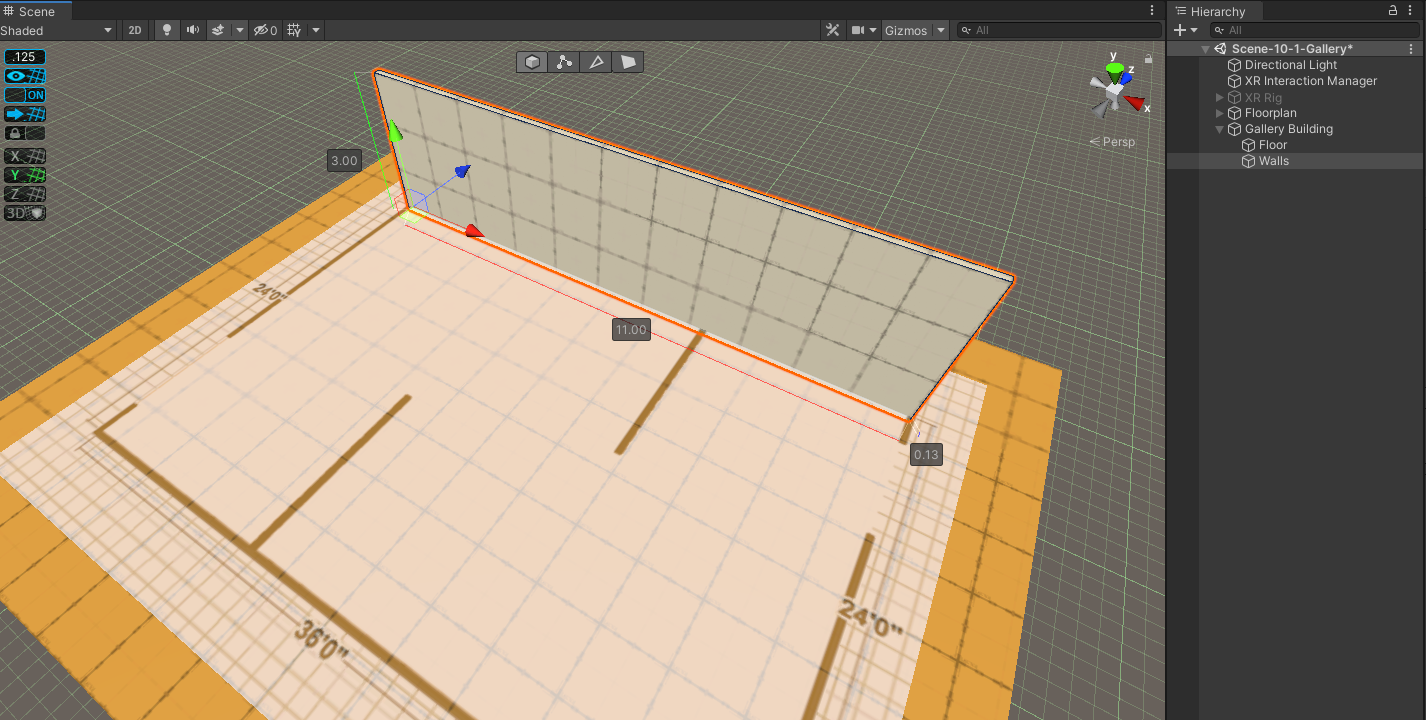
The following screenshot shows a perspective view in the Scene window of this northern wall of the building:
For the east wall along the right of the building, we'll make an edge loop the thickness of the walls (0.125 m) and extrude it in the -Z direction, using the following steps:
- With the Walls object selected, in the ProBuilder edit mode toolbar, select the Edge Selection tool (second icon from the right).
- Select the horizontal edge facing you at the top of the wall.
- In the ProBuilder menu window, choose Insert Edge Loop. This creates an edge loop on the wall.
- On the edge loop in the Scene window, grab the red X axis move cone and slide it toward the right side, leaving a 0.125 m band on the wall, as shown in the following screenshot:

Next, we'll switch into Face Selection mode and select the south-facing narrow face, extruding it to the south-east corner of the building, using the following steps:
- On the ProBuilder edit mode toolbar, choose the Face Selection tool (last icon on the right).
- Select the south-facing narrow face on the wall.
- Extrude the face by pressing Shift +click on the blue Z axis move cone, and drag it toward the south-east corner, as shown in the following screenshot:
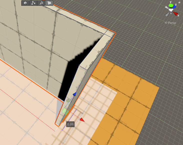
After releasing the mouse click, you can adjust the wall by continuing to click the Z axis and move the cone to the corner, as shown in the following screenshot:

Now, repeat these steps to create the other two walls, as follows:
- On the ProBuilder edit mode toolbar, choose the Edge Selection tool (second icon from the right), and then select a top edge of the east wall.
- From the ProBuilder menu, choose Insert Edge Loop.
- Then, slide the loop to the south corner, leaving a 0.125 band.
- Choose the Face Selection tool (last icon on the right).
- Select the west-facing narrow face on the wall.
- Extrude the face by Shift + clicking on the red X axis move cone, and drag it toward the south-west corner.
- Unclick, and then continue adjusting the wall by clicking the Z axis move coneto the corner.
- Repeat to draw the western wall, connecting to the northern one and completing the enclosure.
Drawing the interior walls is a very similar process, as follows:
- Choose the Edge Selection tool, and then select a top edge of one of the long walls.
- Select Insert Edge Loop and slide the loop into position for the interior wall.
- Select the top edge again, and then Insert Edge Loop, and slide the edge to make the interior wall face 0.125 units wide.
- Choose the Face Selection tool, select the interior wall face, and then Shift + click the blue Z axis move cone to extrude the wall toward the interior of the room.
- Repeat these steps for the opposite interior wall. The result can be seen in the following screenshot:

We now have a floor and walls (both perimeter and interior ones). At present, there's no way to get in or out of the room! Let's add some openings for entrances in the next section.
Making holes for entrances
The entrances on either side of the room are indicated on the sketch drawing as gaps in the walls. We'll use this as a guide to decide where to create ours. There's more than one way to accomplish this. We're going to use Edge Loops again to make new faces for the entrance area, delete them, and then connect the edges of the door frame. To do that, follow these steps:
- Choose Edge Selection mode from the edit mode toolbar.
- Choose a horizontal edge at the top of the wall.
- Select Insert Edge Loop, and drag it into position for one side of the entrance.
- Repeat steps 1-3 for the other side of the entrance.
- Choose Face Selection Mode from the Scene toolbar.
- Select the outward-facing face of the entrance, and press Backspace to delete it.
You might think we're done because you can see through the wall into the room. But the inner-facing side of this wall is still present; it's just not rendered when you're looking from its behind. Let's remove that now, as follows:
- Rotate your scene view so that you're looking at the inside of the wall. The wall entrance is solid again.
- Select the inner-facing face of the entrance and press Backspace to delete it too.
There's one more step to observe. If you examine the door frame, you'll notice there are no faces. We need to add them, as follows:
- Choose Edge Selection mode.
- Shift + click to multi-select both inner and outer edges of the left side of the entrance.
- Select Bridge Edges from the ProBuilder menu to create a new face bridging these edges.
- Repeat steps 1-3 for the right side of the doorframe. The result can be seen in the following screenshot:

Now, repeat all the steps in this topic for the other entrance on the opposite side of the room. With that done, at this point, you can hide the Floorplan sketch image by disabling the Floorplan GameObject. The resulting room now looks like this:

Next, we'll add a roof with a skylight.
Creating a roof and skylight
We'll make a roof from a Cube object, as we've done for the floor and walls. Perform the following steps:
- In the ProBuilder menu window, open the Shape Tool options window, using the + button on theNew Shapeitem (or gear icon if you're in Icon View mode).
- Ensure theShape Selector dropdown is set to Cube.
- Set theShape Settings | Sizeto (11, 0.125, 7.375).
- PressBuildto create the object in the scene.
- Rename the new Cube object in Hierarchy toRoof, and make sure that it's a child ofGallery Building.
- Position the roof at the origin so its top face is exactly at Y=0 level, by setting Position (0.875, 3,-1.25).
To make a skylight in the roof, we'll extrude the face using the Scale Tool, and then delete the faces and repair the edges as we did for the entrance, as follows:
- In the standard Scene edit toolbar (above the Scene window), select the Scale Tool (fourth icon from the left).
- In the ProBuilder edit mode toolbar, select the Face Selection tool.
- In the Scene window, select the top face of the Roof.
- Modify your Scene view so that you can see inside the building, and press Shift + click to also select the inside face of the roof.
- Using the Scale Tool gizmo, press Shift + click on the center of the white square to extrude-scale the roof.
- Shape the extruded planes as you like, using the scale handles, as shown in the following screenshot:

Then, position this extruded face where you want the skylight to be, as follows:
- Change the Unity edit tool to the Move Tool (first icon on the left of the edit toolbar above the Scene window).
- Move the faces to the position you desire.
- Double-check from inside the building that the skylight is not on top of an interior wall!
- Use the Backspace key to delete the faces for the skylight.
As we saw with the entrances, deleting the faces has left unconnected edges on the window frame. Use the Bridge Edges function to fix this, as follows:
- Select the Edge Selection tool.
- Shift + click the two inner and outer edges on one side of the window frame.
- Select Bridge Edges from the ProBuilder menu.
- Repeat steps 2 and 3 for the other three sides of the window frame.
The following screenshot shows the art gallery building from the inside, with directional sunlight streaming in through the skylight:

We have completed the construction of our art gallery building. You can save the model as a non-ProBuilder asset using the Export function in the ProBuilder menu. To export the floor, walls, and roof into a single file, multi-select the three objects when you export (export as a group, including children objects). An exported GalleryBuilding.obj file is included with the files for this project.
Great job! We now have the architectural structure of the room that we'll use for the art gallery, including perimeter walls, interior walls, and a ceiling with a skylight. Now, we can assemble our scene and add the artwork to the gallery.
Assembling the scene
If you've been following along, you now have a scene with the Gallery Building object we just created. If not, perform the following steps to create a new scene and import the building model provided with the files for this chapter:
- Create an empty scene using File | New Scene.
- Save it to a new file,File | Save As, and name it Scene-10-1-Gallery.
- Import the GalleryBuilding.obj file by dragging it from your system explorer into the Project window Assets folder, or use the Assets | Import New Asset... menu.
- Drag the GalleryBuilding from the Project window into the scene Hierarchy.
- Reset its Transform by using right-click | Reset.
Now, we can set up the scene for VR with an XR camera rig. To do this, follow these steps:
- Add an XR rig by selectingGameObject | XR | Stationary XR Rig (orRoom-Scale XR Rig, if you prefer).
- Position the rig at the north-east entrance, setting Position (12, 0, -3) and Rotation (0, -90, 0).
- If your default camera height is on the floor, then, for development, elevate the XR Rig/Camera Offset position to (0, 1.4, 0).
For this project, I'll use a stationary camera rig. If you prefer to make it room-scale, please read theRoom-scale considerations topic at the end of this chapter. We can make the gallery room look nicer by applying some physically-based rendering (PBR) textures next, and then adjust the scene lighting.
Replacing the building materials
We've been using default materials for the building. Let's now improve on that. There are many sources of material textures in the Asset Store and across the internet, both free and for a fee. The textures I am using here have a free-to-distribute license for this book and are from https://3dtextures.me/. The texture files are included with the files for this book, or you can download the same from the following links, and then import them into your ProjectAssets/Textures folder, as usual:
- Wood floor: https://3dtextures.me/2018/02/14/wood-floor-007/
- Plaster walls: https://3dtextures.me/2019/02/15/plaster-rough-001/
To begin, create separate materials for each Floor, Walls, and Roof (ceiling) GameObject of Gallery Building by following these steps:
- In your Project window Assets/Materials/ folder, create a new material, using "+" | Material, and name it Gallery Floor Material.
- Drag the material to the Floor GameObject of the gallery.
- Create another material named Gallery Walls Material, and drag it to the Walls GameObject.
- Likewise, create a material named Gallery Ceiling Material, and drag it to the Roof GameObject.
For the ceiling, let's just keep it smooth (untextured) and white, as follows:
- Select the Roof game object in Hierarchy.
- Set its color to white by selecting Gallery Ceiling Material | Base Map | [color swatch] | #FFFFF.
For the walls, we'll use a plaster material. The textures I found create a pretty dramatic rough texture, so we'll smooth that down so it looks more like textured drywall that you're more likely to see in a gallery. Select the Walls GameObject in Hierarchy, and on its shader Surface Inputs, set the following (if you don't have these files, you can skip these steps):
- Set the color swatch to white (#FFFFFF).
- From the Project window, drag Plaster_Rough_001_COLOR onto the Base Map texture chip.
- Drag Plaster_Rough_001_ROUGH onto the Metallic Map texture chip.
- Drag Plaster_Rough_001_NORMonto the Normal Map texture chip.
- If you see a prompt that the texture has not been imported properly for the Normal Map texture type, click Fix Now. (This will change its Texture Type to Normal Map for you.)
- Drag Plaster_Rough_001_OCC onto the Occlusion Map texture chip.
- Reduce the roughness by setting the Normal Map value to -0.1.
For the floor, we'll use a wood plank flooring material. The textures I found seemed to make the planks too short and narrow, so we'll scale them and darken them a little. Select the Floor game object in Hierarchy, and on its shader Surface Inputs, set the following:
- From the Project window, drag Wood_Floor_007_COLOR onto the Base Map texture chip.
- Set its color swatch to an off-white color (#C5C5C5).
- Drag Wood_Floor_007_ROUGH onto the Metallic Map texture chip.
- Set its Smoothness to 0.333 so it's not too shiny.
- Drag Wood_Floor_007_NORM onto the Normal Map texture chip.
- If you see a prompt that the texture has not been imported properly for the Normal Map texture type, click Fix Now.
- Drag Wood_Floor_007_OCC onto the Occlusion Map texture chip.
- Set Tiling X Y to (0.5, 0.5) to enlarge the textures.
The empty gallery now looks like this:

By the way of a final step in setting up the level design, let's tune the lighting and add a skybox.
Tuning the lighting
Check that your scene lighting is being generated (baked). For this project, it may be simplest to keep the Auto Generate functionality enabled. However, if that gets in the way of your workflow, turn Auto Generate off, but then don't forget to press the Generate Lighting button periodically to re-bake your lightmaps. Follow these steps:
- Open the Lighting window (Window | Rendering | Lighting) (or Lighting Settings in Unity 2019).
- Select the Scene tab.
- Ensure Mixed Lighting | Baked Global Illumination is checked.
- Set Lighting Mode: Baked Indirect.
- Ensure Lightmapping Settings | Progressive Updates is checked in Unity 2020+ (for Unity 2019, choose Lightmapper: Progressive CPU).
- At the bottom, use the Auto Generate checkbox to enable or disable autogenerated lightmaps.
- When Auto Generate is disabled, press Generate Lighting to manually bake the current lightmaps.
In this scene, the user can see the sky from the entrances and skylight. Presently we're using just the boring default Unity skybox. Back in Chapter 2, Understanding Unity, Content, and Scale, I suggested you import the Wispy Skybox asset into the project. If you don't have it yet, you can get it now at https://assetstore.unity.com/packages/2d/textures-materials/sky/wispy-skybox-21737. To add the skybox, follow these steps:
- In the Lighting window, select theEnvironmenttab in Unity 2020 (for Unity 2019, find the Environment section at the top of the Scene tab).
- At the top is a slot for Skybox Material. Press the doughnut icon, which opens the Select Material dialog.
- Search using the wispy string.
- Select one of the skyboxes to use in the scene.
The skybox's sun may not match the angle of your Directional Light, but let's not worry about that right now. However, we can control the interior lighting in other ways. On the same Environment tab or section, proceed as follows:
- Set the Environment Lighting | Source to Color.
- Set the Ambient Color to Warm Sunlight or an incandescent hue such as RGB (190, 180, 160).
Personally, I like the mood this creates. Feel free to experiment and discover what works for you. One more thing. The gallery building will not change in this scene, so we can help Unity optimize its processing by marking it Static, as follows:
- Select the Gallery Building parent in Hierarchy.
- In Inspector, in the upper-right corner, check the Static checkbox.
- When prompted Do you want to enable the static flags for all the child objects as well? press Yes, change children.
- If your baked lighting in this scene looks much darker, try making the Roof game object not static by unchecking its Static checkbox.
Unity may take a few seconds to regenerate the lighting when lightmaps are autogenerating. Alternatively, in the Lighting window, press the Generate Lighting button. We've added some physically-based materials to the walls and floor, and then set up the scene with a skybox, lighting, and baked lightmaps for static objects. Now that we have a gallery, we need to put some art on it!
Creating the artwork rig
Our next step is to create a reusable artwork rig with a picture frame, lighting, information plaque, and a teleportation pod that defines its optimal viewing position. Then, we'll hang the art on the walls of the gallery. We'll construct one rig in the scene, and then save it as a prefab. Later, we'll apply the actual images.
Defining an artwork rig
The artwork rig will consist of a picture frame (cube), a photo plane (quad), and a spotlight, all relative to the artwork's placement on the wall. Let's get started by doing the following:
- Create a container object by navigating toGameObject|Create Empty, renaming it ArtworkRig.
- Create the frame. WithArtworkRigselected, right-click and select3D Object|Cube, and name it ArtFrame.
- Leaving the origin of the rig at floor level, let's set the default height of the art image frame at 1.4 meters high. InInspector, set the ArtFrame Position to (0, 1.4, 0).
- Give it some thickness, setting itsScale Z value to0.05.
- Also, let's assume a3:4aspect ratio, so set itsScale Yvalue to0.75 (scale 1, 0.75, 0.05).
Place the ArtworkRig on the wall facing the north-east entrance (upper-right corner of the plan sketch). It may help to hide the Roof of theGallery Buildingobject (uncheck itsEnablecheckbox option) and change theSceneview to a top-down view and Iso. Now, place the ArtworkRig on the wall, as follows:
- Select the parent ArtworkRig object.
- Rotate it to face east, Rotation (0, -90, 0).
- Use the Move Tool to position it on the wall. The Position that works for me is (8.3, 0, -2.9).
Next, we'll build up the artwork rig by adding an image placeholder mounted on a black matte board, as follows:
- Make the frame black. Navigate toAssets|Create|Material, and name itArtFrame Material.
- Set its Base Map color to a charcoal black color.
- Uncheck its Specular Highlights and Environment Reflections checkboxes so that it renders matte.
- Then, inHierarchy, select theFrameoption, and drag theArtFrame Materialmaterial toArtFrame.
- To make the image placeholder, withArtFrame selected in Hierarchy, right-click and navigate to3D Object|Quad.
- Name itImage.
- Position Image just in front of the frame so that it's visible; setPositionto (0,0,-0.8), and scale it so that it's slightly smaller than the frame by settingScaleto (0.9,0.9,1).
- Create a material for the images. Navigate toAssets|Create|Material, and name itArtImage Material.
- Drag ArtImage Material to the Image object.
- Set the Base Map color to white so that the photo's full texture fidelity will be rendered. Leave Specular Highlight and Reflections enabled if you want the photos to have a glossy finish.
Usually, any artwork has a spotlight shining on it. Let's add that now.
Adding a spotlight
Let's add aspotlight to the rig and bake it, as follows:
- First, put the ceiling back in by checking off theEnablecheckbox option for the Roof child object ofGallery Building.
- WithArtworkRigselected inHierarchy, right-click and navigate toLight|Spotlight.
- Position it one and a half meters away from the wall (Z=-1.5) and up near the ceiling. The exact height doesn't matter much since we don't actually have a light fixture. I setPositionto (0,2.4,-1.5).
- Now, adjust theSpotlightvalue so that it appropriately illuminates the artwork. I setRotation Xto30. Adjust the light parameters to your liking, such as Inner/Outer Spot Angle (38, 45), Range to 3, and Intensityto3.
- Set the light Color to white (#FFFFFF).
- The lights will not move so we can bake it, but the frame will be dynamically resized (see later in this chapter), so set Light | Mode to Mixed.
We set the light mode to Baked to reduce the runtime costs of shading and shadow calculations. Likewise, we can make the entire artwork rig Static, since it won't be moving at runtime either. Then, let's save the rig as a prefab before we duplicate it throughout the scene. This will make it easier to make changes later that propagate to all the instances in the scene. Proceed as follows:
- SelectArtworkRiginHierarchy.
- Enable the Static checkbox in the upper-right corner of its Inspector. When prompted Do you want to enable the static flags for all the child objects as well? press Yes, change children.
- Save the rig as a prefab,and drag it to your ProjectAssets/Prefabsfolder.
The results are shown in the following screenshot:

Now, we can set up the exhibition by placing artwork throughout the gallery.
The exhibition plan
The next step is to duplicate theArtworkRigon eachwall where we want to display the images. Position it and rotate as needed. If you follow the plan shown in the following diagram, your exhibition will display 10 images, indicated by the stars:

The following are the steps to take to duplicate theArtworkRigon each wall:
- As before, it may be easier to hide the ceiling and change theScene Viewpanel toTop and Iso.
- On the top left of theScene Viewpanel, change the Transform Gizmo toggles so that the tool handle is placed at thePivotpoint rather thanCenter. See the following screenshot:

- Create a newEmptygame object,Resetits transform, and name itArtworks.
- Drag the existingArtworkRig so it's a child of Artworks.
For each location, place anartwork in the gallery. You may need to first turn off Snap to Grid if you presently have it enabled, and then follow these steps:
- Select an existingArtworkRig in theHierarchy.
- DuplicateArtworkRig by right-clicking onDuplicate, or by pressingCtrl+D.
- Rotate the rig so that it faces the correct direction by settingRotation Yto0,90,180, or-90.
- Position the rig on the wall.
The settings that work for my gallery are provided in the following table (and assume your Artworks transform is reset to the origin):
| Index | Position X | Position Z | Rotation Y |
| 0 | 8.3 | -2.9 | -90 |
| 1 | 11.75 | -6.2 | 90 |
| 2 | 9.3 | -8.475 | 180 |
| 3 | 6.5 | -8.475 | 180 |
| 4 | 4.77 | -7 | -90 |
| 5 | 8.1 | -3 | 90 |
| 6 | 5.7 | -1.4 | 0 |
| 7 | 2.9 | -1.4 | 0 |
| 8 | 1 | -4 | -90 |
| 9 | 4.6 | -7.1 | 90 |
The following screenshot shows the player's view of the scene so far:

Well, this is starting to look pretty good. So far, we've created an art gallery building, created an artwork prefab rig, and arranged the rigs on the walls to set up the exhibition. Now, we just need to put some lovely pictures into those picture frames.
Adding pictures to the gallery
Please find 10 of your favorite photosfrom your photo library to use and add them to a newProject Assetsfolder namedPhotos. Or, use the ones I've included in the files for this book, a collection of freely usable nature photos found on Unsplash (https://unsplash.com/). Add the photos as follows:
- Create a photos folder, then navigate toAssets|Create|Folderand name itPhotos.
- Import 10 photos by dragging and dropping them from your OS file explorer into the Photos folder that you just created (or navigate to Assets | Import New Asset...).
We are going to write a script named PopulateArtFrames that, given the list of images, will add them to each ArtworkRig in the scene. Create the script as follows:
- InHierarchy, selectArtworks.
- Then, inInspector, navigate toAdd Component|New Scriptand name itPopulateArtFrames.
- Open the new script for editing, as follows:
public class PopulateArtFrames : MonoBehaviour
{
    public Texture[] images;

    void Start()
    {
        int imageIndex = 0;
        foreach (Transform artwork in transform)
        {
            GameObject art = artwork.Find("
                ArtFrame/Image").gameObject;
            Renderer rend = art.GetComponent<Renderer>();
            Material material = rend.material;
            material.mainTexture = images[imageIndex];
            imageIndex++;
            if (imageIndex == images.Length)
                break;
        }
    }
}
What is going on here? First, we declare a public array ofTexturesnamedimages. You will see that this will appear in the Inspector, so we can specify which photos to include in the scene.
This script is attached to the Artworkscontainer object, which contains as children the ArtworkRigs. When the app starts, inStart(), we loop through each of the ArtworkRigs, finding its Image child object. For each image, we get its Renderer component's Material, and assign a new Texture, that being the next image in the list. We use animageIndexvariable to increment through the list, and stop when we've run out of images or run out of ArtworkRigs without causing an indexing error.
The astute reader may wonder why, since all the ArtworkRig Image objects use the same Material, wouldn't changing the material on any one objectchange them all? In fact, Unity takes care of that by cloning the material into a new unique one when you modify its texture (or other attributes) at runtime. So, each ArtworkRigsImage gets its own Material with its own Texture, and thus, each picture in our gallery is different.
To finish this up, let's perform the following steps:
- Save the script and return to the Unity editor.
- WithArtworksselected inHierarchy, unfold thePopulate Art Framesscript component inInspectorand unfold theImagesparameter.
- Set theImages Sizevalue to10.
- Find the images you imported in thePhotosfolder under ProjectAssets/ and drag them, one at a time, into theImagesslots asElement 0throughElement 9, as shown in the following screenshot:

When you click onPlay mode, the artwork in the scene will get populated with the images in the order that you specified. Here's a view from inside the gallery:
That's pretty nice! We could stop here, but let's suppose wewant to track more data than just the images for each artwork, such as artist, title, and description. Let's add the ability to add metadata to our photos.
Managing art info data
We will consider several software design patterns to manage metadata associated with each photographic art piece, including in the first two sub-topics—separate lists and data structures—for your edification. Then, we'll actually use Scriptable Objects (explained next) as the preferred data management technique in our project.
Using lists
One approach to adding more data about each photo could be toadd more lists to thePopulateArtFramesscript, one for each of the data fields. For example, the script may contain the following code (no need to add this code yourself—this is only for teaching purposes):
 public Texture[] images;
 public string[] titles;
 public string[] artists;
 public string[] descriptions;
In such a case, theInspectorwould show the following (I limited the list to four items for brevity):

As you can imagine, this could get very unwieldy. To change the fourth image in the scene (Element 3), for example, you'd have to go to all the lists and change the Element 3 item in each list separately (Images, Titles, Artists, Descriptions), which makes it easily prone to mistakes and hard to maintain. Things could get very out of sync.
Using data structures
A better approach could be to write a C#struct(orclass) as a data structure that contains each of the fields we want, and then make the list inPopulateArtFramesas this type. For example, the script may read as follows (no need to add this code yourself—this is only for teaching purposes):
[System.Serializable]
public struct ArtInfo
{
    public Texture image;
    public string title;
    public string artist;
    public string description;
}

public class PopulateArtFrames : MonoBehaviour
{
    public List<ArtInfo> artInfos = new List<ArtInfo>();
In the preceding example snippet, we declare a separate data structure namedArtInfodefining our data fields. Then, inPopulateArtFrames, we declare it as aList(which must be initialized with thenew List<ArtInfo>()call). In the script, we'd then reference the textures—for example, asartInfos[i].image. Also, we need to say that it isSystem.Serializableso that the list appears in the editorInspector, as follows:

Now, we have a list ofArtInfoelements that we can fill in, and the data for each element is grouped together. Another benefit of this structure is it could be more easily populated from an external data source, such as a cloud-based JavaScript Object Notation (JSON) or comma-separated values (CSV) file, or a database query.
Using scriptable objects
In the previous examples, the art infodata is maintained on aGameObject in the Scene hierarchy. As a software design, this is not really where the data belongs. Data objects are not game objects and should be managed separately. In the Scene hierarchy, we define the level design and game behaviors. ArtworkRigs have spatial transforms, renderers, and other components for runtime behaviors, including physics. But other data can live outside the scene hierarchy. For this, Unity offersScriptable Objects. Let's see how to manage our art info data as Scriptable Objects. Begin by writing a new ArtInfoData script for the Scriptable Object, as follows:
- In the Project window Asset/Scripts/ folder, right-click and select Create | C# Script.
- Name the scriptArtInfoData.
- Then, open theArtInfoData.csscript for editing, as follows:
[CreateAssetMenu(menuName = "My Objects/Art Info")]
public class ArtInfoData : ScriptableObject
{
    public Texture image;
    public string title;
    public string artist;
    [Multiline]
    public string description;
}
Rather than inheriting from MonoBehaviour, we define this class as a ScriptableObject. Since scriptable objects are not added to the scene Hierarchy, we need a way to create them in the ProjectAssets folder. At the top of the script, I've added a CreateAssetMenu attribute, which generates a menu item in the Unity Editor for the object. Using this attribute makes it easy, as follows:
- Save the script and return to Unity.
- In theProjectwindow, select yourPhotosfolder where you imported your image textures. We'll create the ArtInfoData objects in the same folder.
- In the Unity editor's main menu, navigate toAssets|Create.
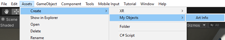
- You will see a new item,My Objects, with a submenu with an Art Info item, as directed in the CreateAssetsMenu property attribute in our script, as shown in the following screenshot:
- ChooseArt Infoto create an instance. It may be helpful to name the object similar to your images. For example, if you havePictureA, name itPictureA Info.
- Drag the image texture onto the scriptable object'sImageslot.
- Add information for theTitle,Artist, andDescriptiontoo.
Here is a screenshot of an ArtInfoData object with some data filled in:

Repeat these steps for all your pictures. When you're done, your art data will be Project assets along with the photo images.
Now, to use these scriptable object assets in the project, we could modify the PopulateArtFrames script to use a list of the ArtInfoData asset objects we just created. But to make this more object-oriented, we'll refactor how we did it before. We're going to eliminate the PopulateArtFrames script and instead, let each artwork rig populate its own data. Let's write a new ArtInfo script for the ArtworkRig that takes an ArtInfoData object and sets up its own image based on the given data object. Create a new script namedArtInfo and open the script for editing, as follows:
public class ArtInfo : MonoBehaviour
{
    public ArtInfoData artInfo;
    public GameObject image;

    private void Start()
    {
        Renderer rend = image.GetComponent<Renderer>();
        Material material = rend.material;
        material.mainTexture = artInfo.image;
    }
}
Save the script. In Unity, remove the Populate Art Frames component from the Artworks object, and open the ArtworkRig prefab for editing, as follows:
- In Hierarchy, select the Artworks object and, in Inspector, remove the Populate Art Frames component by right-clicking | Remove Component (or using the three-dot icon menu).
- In the Project windowAssets/Prefabs/folder, open theArtworkRigprefab for editing by double-clicking it.
- Drag the ArtInfo script we just created from the Project window onto the ArtworkRig object.
- Drag the Image child onto theArt Info | Imageslot.
- Leave the Info Data slot empty for now.
- Press Save to save the prefab, and return to the Scene Hierarchy.
The following screenshot shows the ArtworkRig prefab being edited as I described, with the Art Info component:

Now, in Inspector, we just need to assign the Art Info data objects to each rig object. The following screenshot shows one of the ArtworkRigs set up:

PressPlay. The artwork images get loaded during Start just like before, but we've made the underlying implementation more object-oriented. By making each ArtworkRig responsible for its own data rather than using a top-down controller for populating the data, and using Scriptable Objects for the art info data, we have extended our app to handle more info about each art picture. Now, we can go ahead and show this info within the gallery.
Displaying the art info
We now have more information oneach art piece, and can incorporate that into our scene. We will add a world space user interface (UI) canvas to the ArtworkRig. If you'd like a reminder introduction to Unity's canvas and UI elements, please look atChapter 6, CanvasingWorld Space UI.
The info plaque will be a small canvas next toeach picture, with a title text UI element. Let's build it into the ArtworkRig prefab. Open theArtworkRig prefab for editing. Then, add a world space canvas, as follows:
- Add a child canvas,GameObject| UI |Canvas, and name it InfoPlaque Canvas. (Note: if you wanted to make any of the UI on this canvas interactable, you should use XR | UI Canvas instead).
- Set itsRender modetoWorld Space.
- Set the canvasWidth:640,Height:480, Rotation (0, 0, 0).
- If you recall, the canvas scaled in world space will be 640 meters wide! Set theScale XYZto0.0006.
- Next, create a child panel, + | UI | Panel.
- Visually adjust the position of InfoPlaque Canvas using the move gizmo. I found this works:Pos(0.8,1,-0.01). (Leave the child panel at 0, 0, 0).
Now, we can add text UI elements for the title, artist, and description. I'll use a Vertical Layout Group for this. In the following, I provide my recommended settings (you can do what works for you):
- On the Panel game object, add a Vertical Layout Group using Add Component | Layout | Vertical Layout Group.
- Set the Child Alignment to Middle and Center.
- Check the checkboxes for Control Child Size: Width and Height and Child Force Expand: Width and Height.
- Add a child text element to the panel, usingCreate UI|Text - TextMeshPro, (or simply Text if you don't have the TextMeshPro package installed), and rename it Title.
- Set some default title text in Text Input, such as [Title text].
- Use the following settings: Font Size | Auto Size checked; Vertex Color to black;Alignment:Middle, Center; Wrapping:Enabled;Overflow:Overflow; Extra Settings | Margins | Left:40, Right:40.
- Duplicate the Title element, and rename it Artist. Set its Text Input to [Artist name] and Auto Size Options | Max |48, and Font Style: I (for italics).
- Duplicate the Title element again, rename it Description, set Text Input to [Description text], and Auto Size Options | Max | 48.
One more thing. Previously, we decided that the ArtworkRig can be Static in the scene. This should also be the case for the new UI canvas.
- With the InfoPlaque Canvas selected, check that the Static checkbox is in Inspector.
- Answer Yes Change Children, when prompted.
- Save the prefab changes.
Now, we can modify theArtInfo script to add new variables for the text UI elements and set their textproperty, as follows:
using TMPro;
using UnityEngine;

public class ArtInfo : MonoBehaviour
{
    public ArtInfoData infoData;
    public GameObject image;
    public TMP_Text title;
    public TMP_Text artist;
    public TMP_Text description;

    private void Start()
    {
        Renderer rend = image.GetComponent<Renderer>();
        Material material = rend.material;
        material.mainTexture = infoData.image;

        title.text = infoData.title;
        artist.text = infoData.artist;
        description.text = infoData.description;
    }
}
That was easy. Save the script, and then, while still editing the ArtworkRig prefab, assign the UI elements to the variable slots, as follows:
- Drag the Title element from Hierarchy to the ArtInfo | Title slot.
- Drag the Artist element to the ArtInfo | Artist slot.
- Drag the Description element to the ArtInfo | Description slot.
- Save the prefab edits.
The following screenshot shows the ArtworkRig prefab being edited, and its ArtInfo component populated with the UI text elements:

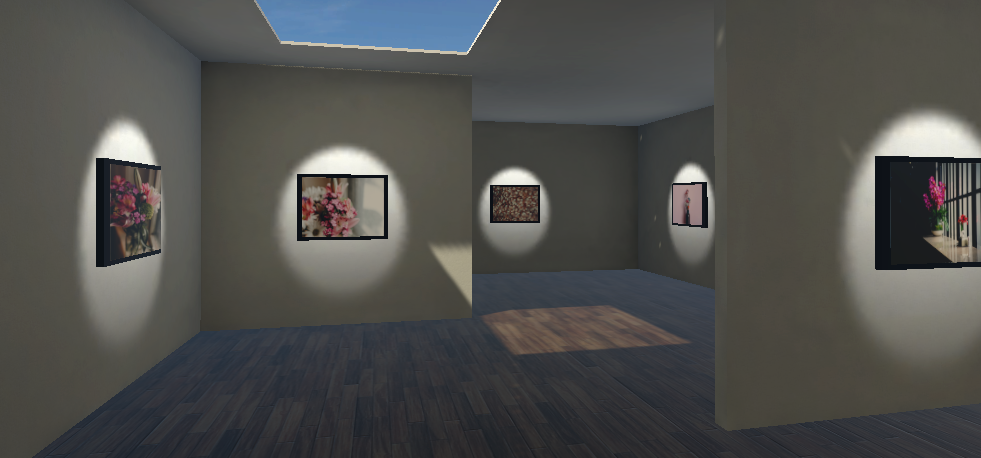
Now, when you pressPlay, the pictureimages and title text will get initialized onStartfor each of the artwork rigs. Here's one of the photos with its info plaque:

So, now, we have a good-looking art gallery room, with art rigs strategically arranged on the walls throughout the room. We manage the art data using scriptable objects that define the artwork for each station. At present, we've defined all the pictures with a 4:3 aspect ratio, but that's not the actual shape of many of our photos. Let's fix that next.
Adjusting for image aspect ratio
You probably noticed that some ofyour pictures appear squished, since our framed image is shown at a fixed size and aspect ratio. What we really would like is for the frame and image to adjust themselves, depending on the dimensions of the image.
When Unity imports a texture, it prepares it (by default) for graphics processing unit (GPU) rendering as an object material texture, which includes resizing it to a square power of two (for example, 1024 x 1024, 2048 x 2048). If you adapt your project to load images at runtime—for example, from theResourcesdirectory, or from the device's photostream, or over the web—then you will probably have access to the image file's metadata header that includes its pixel width and height. Unfortunately, because of using imported textures, Unity only provides the size of the imported scaled image, not the originals. One solution is to change the Advanced Import Settings for the images we're using, as follows:
- From yourProjectAssets/Photos/folder, select an image texture.
- InInspector, underAdvanced, changeNon Power of 2toNone.
- PressApply.
Repeat this for each image in the project. (You can multi-select images in the Project window using Ctrl + click and change all their settings at once). Note that this also decompresses the image, so what might start out as a 400k.jpgfile becomes a 3 MB file, or a 24-bit image in the project, so be cautious of the width and height of the source images you choose to use.
InArtInfo.cs, add the following helper function, which returns a normalized scale of a texture. The larger dimension will be1.0and the smaller one will be a fraction. For example, an image that is 1024w x 768h will get a scale of (1.0,0.75). It also maintains the current relative scale of the picture using the Z scale value, since that's not changed by our aspect ratio calculation, but will be changed by the Scale tool!
ModifyArtInfo first by adding a TextureToScaleprivate function that normalizes the image scale to 1.0 for the larger of width or height, and sets the other dimension to the aspect ratio, as follows:
    private Vector3 TextureToScale(Texture texture, Vector3 scale)
    {
        if (texture.width > texture.height)
        {
            scale.x = 1f;
            scale.y = (float)texture.height / (float)texture.width;
        }
        else
        {
            scale.x = (float)texture.width / (float)texture.height;
            scale.y = 1f;
        }
        return scale;
    }
The function takes the original scale of the frame and modifies the X and Y scale, but preserves the original framedepth (Z). Add a new public variable for theframe, as follows:
public Transform frame;
And then, add this line to set the frame's scale:
frame.localScale = TextureToScale(infoData.image, frame.localScale);
Save the updated script. Then, in Unity, add the frame reference. Also, now that we're changing the frame at runtime, it should no longer be flagged as Static. Proceed as follows:
- Open the ArtworkRig prefab for editing.
- Drag theArtFrameto the Frame slot in the component.
- With ArtFrame selected in Hierarchy, uncheck its Static checkbox in Inspector, and answer Yes, Change Children when prompted.
- Save the prefab.
Now, when you play, the framed images are scaled with the correct aspect ratio, like the one shown here:

Wow, this is pretty exciting! Viewing the scene in VR, I really wish I could move around the gallery and look at each photo up close. Let's add teleportation to that.
Teleporting around the gallery
We've done so much, and yet have not discussed moving throughout the gallery level. In Chapter 7, Teleporting, Locomotion, and Comfort, we examined various ways of implementing locomotion and teleportation. Let's now set up specific teleportation spawn points that provide an optimal viewing pose for each artwork picture in the gallery.
We'll begin by adding the XR Interaction Toolkit's Locomotion System to our scene, including teleportation and snap turning. You can set it all up component by component (Teleportation Provider, Snap Turn Provider, XR Ray Interactor line types and renderer, and so on). For brevity, let's just borrow the demo rig provided with the Unity XR Interaction Toolkit examples we already installed in Chapter 7, Teleporting, Locomotion, and Comfort (and which can be found at the following GitHub repository: https://github.com/Unity-Technologies/XR-Interaction-Toolkit-Examples). Add the XRRig Demo object to the scene with the following steps:
- In the Project window, search for XRRig_Demo (for example, Assets/Prefabs folder) and drag the prefab into your Hierarchy.
- Copy the XR Rig | Transform you had (right-click | Copy Component), and paste it onto the new XRRig_Demo | Transform (right-click | Paste Component Values).
- Delete the XR Rig you had.
Or, if you prefer to set it up manually yourself, start with the following steps:
- Select the XR Rig in Hierarchy.
- Add a Locomotion System by selecting Add Component | search locomotion | Locomotion System.
- Add a Teleportation Provider to the XR Rig by selecting Add Component | search teleport | Teleportation Provider.
- Add Snap Turn Provider by selecting Add Component | search snap | Snap Turn Provider.
- Wire up the thumbsticks on both controllers. Set Snap Turn Provider | Size to 2, and then drag LeftHand Controller and RightHand Controller to the Element 0 and Element 1 slots.
- Set up the ray line visualizers on the controllers—for example, change its XR Ray Interactor | Line Type to Projectile Curve and modify the XR Ray Interactor, Line Renderer, XR Interactor Line Visual as needed, as well as create a new Material for Line Renderer.
Now, we can update ArtworkRig to offer a teleport pod, taking the player to an ideal viewing position in front of each picture. I suppose a good viewing position is about one and a half meters back from the picture. We can add a TeleportAnchor object at that location, within ArtworkRig, on the floor. Let's add that now, as follows:
- Open the ArtworkRig prefab for editing.
- From the Project window, locate the TeleportAnchor prefab (use the search field) (for example, in Assets/Prefabs/).
- Drag it to the scene and set its Positionto (0,0,-1.5).
- Create a material for the anchors. Navigate to Assets | Create | Material, and name it TeleportAnchor Material.
- Set the material's Shader to Universal Render Pipeline/Unlit, Surface Type to Transparent, and Base Map color to black with Alpha40.
- DragTeleportAnchor Materialto the Teleport Anchor | Mesh Renderer | Materials | Element 0 slot.
- Save the prefab.
Conveniently, in the ArtworkRig, the anchor is always facing the photo, so when the entire rig is positioned in the room, and the player teleports, the player will always end up facing that particular rig's image.
That should do it! Press Play. You can now press down on the thumbstick button and point the hand controllers at a teleport anchor, and it'll highlight. Click the trigger (or whichever button you've configured) to teleport to that location and be turned facing the picture at that station. Here is a screenshot of me teleporting to a new spot in the gallery:

If you're sitting comfortably in a chair enjoying the gallery, this works well. But there could be trouble if you get up and walk around in VR. Let's discuss this problem next.
Room-scale considerations
The gallery-level layout we have designed works best in seated or standing tracking mode. Our use of the zig-zag partitions, for example, is not a good idea in room-scale VR unless you take care to not allow the player's play space (chaperone boundaries) to cross these walls. This can be done, but you would need to make the overall space larger, perhaps adaptive to the actual play-space size, and add conditions to the teleportation feature that we implement later in the chapter, complicating our examples.
The following screenshot is a depiction of an initial position for XR Rig, showing that the play-area boundaries (green lines) fit neatly within the gallery viewing space for the first ArtworkRig. It may not fit so easily at the other viewing situations, so you'd need to make adjustments to discourage the player from walking through walls. Also, while this is the default length and width, the player's actual space will vary to their configuration. To fully accommodate these possibilities, it may be necessary to go to a procedurally generated level layout, where the position and scale of the walls are determined at runtime based on the player settings. Have a look at the XR Rig position here:

As you can see, the level design for VR has many considerations, such as whether the player is stationary or using room-scale tracking; whether this is expected to be a passive experience or one with a lot of interactivity; whether the game objects (and lighting) are stationary and can be marked static, or will be changing at runtime.
Summary
In this chapter, we built an art gallery scene from scratch, starting with a 2D plan, drawing and using the ProBuilder tools to construct a 3D architectural structure. We built a scene around the model, adding PBR materials and environmental lighting. Then, we built an artwork rig consisting of an image, a picture frame, and a spotlight, and placed instances of the rig on various walls throughout the gallery. Next, we imported a bunch of personal photos and wrote a script that populates the art frames at runtime. Adding more detailed data about each piece of artwork, we explored several ways of managing lists of non-graphical data and settled on an object-oriented approach, where each rig is responsible for handling its own data, stored in Scriptable Objects. Finally, we added the ability to teleport around within the art gallery level, using the XR Interaction Toolkit locomotion system.
You have learned some of the basics of mesh editing and 3D modeling, while further exploring issues of lighting, rendering, and materials. You learned different design patterns for managing data apart from GameObjects and MonoBehaviours, including Scriptable Objects that are kept as project assets but not in the scene hierarchy. These are important skills for any 3D Unity project, but especially VR ones.
In the next chapter, we will take a look at a different kind of VR experience, using pre-recorded 360-degree media. You will build and learn about photospheres, equirectangular projections, and infographics.