
Up to now, we've focused on the mechanics of developing interactive 3D scenes, starting with understanding 3D coordinates and scale, to interacting with your gaze and your hands, then displaying text and user interface (UI) elements, and finally, moving through the scene with locomotion and teleportation. In this chapter, we consider a different yet equally important aspect of your virtual reality (VR) project—the visual fidelity of your scene. We will examine many of Unity's powerful tools for lighting, rendering, and realism.
Rendering and lighting are complex topics, broad and deep. It can take years of experience and artistic skills to master the quality we have come to expect in AAA video games and Hollywood movie productions. Unity is amazing because it provides many simple, easily accessible tools for getting your scenes to look very good even if you have limited experience, while also providing a plethora of controls, parameters, and components that would please even the most advanced, perfectionist, visual artist. Unity also appreciates the division of roles between artists and developers. As an artist, you can create 3D assets outside of Unity and import them into the project, and then control and refine materials, textures, and illumination. As a developer, you can build the scenes, script behaviors, design game mechanics, and refine the player experience with temporary artwork, and, at a later time, integrate the actual assets.
In this chapter, we'll learn about lighting and rendering to make the scene look realistic. The project will be the inverse of the other projects in this book—that is, instead of starting with an empty scene and building up the project step by step, we will start with an existing scene and see what happens when you remove or modify existing properties. The scene will be the default SampleScene that Unity includes when you create a new project using the URP template. As we examine different topics in rendering and lighting, we'll add UI controls and scripts for manipulating some settings so that you can see first-hand the effects in VR.
We will begin by reviewing the workflow and best practices that Unity recommends for planning your lighting. After setting up our in-game menu panels, you'll learn about environmental lighting. Then, you'll learn more about materials, including how to modify shader parameters from C# scripts. Next, we'll look at lighting GameObjects and light emission with Materials that contribute to lighting in the scene. After that, you'll see how adding Light Probes and Reflection Probes can really improve the realism and fidelity of your graphics. Finally, we'll look at the post-processing effects, which can be the crowning finish to making your scene look more realistic and cinematic. In this chapter, we will cover the following topics:
- Lighting and rendering strategies
- Using environmental lighting
- Using physically based rendering (PBR) materials and Universal Render Pipeline (URP) Shaders
- Using Light objects and Emission surfaces
- Using Light Probes and Reflection Probes
- Enhancing your scenes with post-processing effects
The intent of this chapter is to give you an interesting overview of the many, many ways of controlling lighting in your VR scenes. By the end of this chapter, you should have a richer understanding of lighting in VR and a launching point for your own explorations.
We will begin with a discussion of the key concepts and an overview of Unity's lighting and rendering tools.
Technical requirements
To implement the projects and exercises in this chapter, you will need the following:
- PC or Mac with Unity 2019.4 LTS or later, an XR Plugin for your device, and the XR Interaction Toolkit package installed
- A VR headset supported by the Unity XR Platform
You can access or clone the GitHub repository for this book (https://github.com/PacktPublishing/Unity-2020-Virtual-Reality-Projects-3rd-Edition-) to optionally use assets and completed projects for this chapter, as follows:
- All completed projects in this book are in a single Unity project at UVRP3Projects.
- The completed assets and scenes for this chapter are in theUVRP3Projects/Assets/_UVRP3Assets/Chapter08/folder.
Lighting and rendering strategies
Lighting your scenes starts with your project's requirements and your own decisions about the look and style you are aiming for. Do you want high-quality realism or simpler geometric rendering? Do you want lifelike objects or cartoon-like graphics? Are you lighting an outdoor scene or an indoor one? Just as important, you also need to ask yourself what are the primary target platforms, especially: is it mobile, desktop, or console? At some point in your projects, before creating the final assets and lighting, you need to figure out your lighting strategy, as Unity recommends:
In this section, I'll try to break down the different types of lighting sources and settings you can use in your project. First, some definitions, as follows:
- Direct lighting is emitted, hits a surface once, and is then reflected into the camera.
- Indirect lighting is any other light that ultimately is visible, including multi-bounced light and sky.
- Global Illumination (GI) refers to the combination of direct and indirect lighting that provides realistic lighting results.
- Real-time lighting is calculated at runtime.
- Bakedlighting is precomputed before your program is built and saved as lighting data (such as Lightmap images) and used at runtime.
- Mixed lighting is when your project utilizes a combination of real-time and baked lighting.
- Render Pipelineis the sequence of operations performed to draw a scene on the screen. Unity lets you choose between multiple render pipelines.
- Shader is a program running on the graphics processing unit (GPU) that calculates the value of each pixel on the screen from a set of geometry and texture data prepared by the central processing unit (CPU).
I will refer you to the Lighting strategy article in Unity Best Practices Guides: Making Believable Visuals In Unity (https://docs.unity3d.com/Manual/BestPracticeMaking
BelievableVisuals3.html), which outlines five different common lighting setups, as follows:
- Basic real-time lighting: The specular highlights from the light are visible, but there is no indirect lighting.
- Baked lighting: Soft baked shadows are visible, and static indirect lighting is visible in high resolution, but there are no specular highlights from lights, and dynamically lit GameObjects don't cast shadows.
- Mixed lighting: Similar to bakedlighting, but there is a specular response from lights, and dynamically lit GameObjects do cast shadows.
- Real-time lighting and GI: Proper indirect lighting response and specular response are visible, and lights are all moveable and updateable, but there's no angular soft shadow.
- All options enabled: Depending on the settings of each light, you can achieve a combination of all the preceding options.
Open the Lighting settings window by selecting Window | Rendering | Lighting, and review the options. Your settings can vary from one scene to the next in your project. The Scene tab settings are shown in the following screenshot, where the Baked Global Illumination Mixed Lighting option with Lighting Mode is set to Baked Indirect. Review the other many Lightmapping Settings shown here:

Given that you have an idea of your visual requirements and target platforms, the first step in setting up your lighting strategy is to choose a Render Pipeline for the project, and then choose lighting settings and light GameObjects in the scene.
Choosing a Render Pipeline
In setting up a new Unity project, one of the very first decisions you make is to choose a render pipeline. We did this at the start of this book and decided all of our projects will use the URP, picking the corresponding template from the Unity Hub. A render pipeline performs a sequence of operations that displays the content of a scene onto the screen, frame by frame. Different render pipelines have different capabilities and performance and are suitable for different applications and platforms. A render pipeline is responsible for three major process steps, as follows:
- Culling: The first step is to list the objects to be rendered, choosing only the objects visible in the camera frustum (viewing volume) and eliminating those occluded (obscured) by other objects.
- Rendering: The second stage is drawing the objects into pixel buffers, with correct lighting, shadows, reflections, and so on.
- Post-processing: The final stage is performed on the pixel buffers before being copied onto the display screen, including effects such as bloom and color grading.
Prior to Unity 2019, Unity had a single Built-in Render Pipeline. Presently, this is still available and may be selected using one of the first three templates when creating a new project in the Unity Hub. The last two options, for High Definition Render Pipeline (HDRP) and URP, use the new Scriptable Render Pipeline (SRP) instead of the built-in one. I recommend you use one of these, such as Universal Render Pipeline, if you can, as this is the future of Unity. This option is shown in the following screenshot:

In addition to the HDRP and URP pipelines provided with Unity, you can create your own custom ones. The SRP pipeline allows you to control rendering via a C# script, giving graphics programmers very advanced control over the processing and rendering details of their projects.
In your project, you set up the Scriptable Render Pipeline Settings in the Graphics settings window, found by navigating to Edit | Project Settings | Graphics, as shown in the following screenshot. Details can be found in the Unity Manual (https://docs.unity3d.com/Manual/class-GraphicsSettings.html):

When using a Scriptable Render Pipeline, its settings are stored in a separate data asset file found, by default, in the Assets/Settings/ folder. In the Settings window shown in the preceding screenshot, it's referencing the UniversalRP-HighQuality asset.
Clicking that asset, you can review and modify its settings in the Inspector, as shown in the following screenshot:

I won't go into the meaning of each individual setting here, as this can be found in the Unity Manual. As you can see, it is wise to choose your Render Pipeline before you even create and start your project. It can be changed later, but it's always best sooner rather than later. The key points to remember include the following:
- It can be difficult and disruptive to switch a project from one Render Pipeline Instance to another. For example, Shaders written specifically for HDRP may not work properly with URP.
- With a Render Pipeline Instance chosen, you can modify its graphics settings by inspecting its corresponding data asset.
- You can save and use different configurations of settings for your chosen render pipeline by creating new Render Pipeline data asset files. You can change Render Pipeline settings assets at runtime but they must reference a compatible Render Pipeline Instance.
Having decided on a Render Pipeline, the next step in your lighting strategy is to choose the Lighting settings and add Light GameObjects to the scene.
Choosing Lighting Settings and GameObjects
I recommend you review the flowcharts and decision trees found in the Unity Best Practices Guide (https://docs.unity3d.com/Manual/BestPracticeLightingPipelines.html) for developers deciding how to light a project. That article includes detailed decision trees and comparisons of settings and options. Along the main decision tree, as mentioned in the previous topic, your first step is to select a render pipeline for the project. In the book, we always use theUniversal Render Pipeline option, which provides the best performance for a wide range of target devices including VR.
The next step in establishing a lighting strategy is to pick a Global Illumination mode. My recommendation is to choose Mixed Lighting by default, by checking the Baked Global Illumination option in the Lighting settings window. Then, you'll need to pick a mode from the Lighting Mode option. Not all modes are available for all render pipelines but they are all listed here:
- Subtractive—almost 100% baked, with directional light shadowing for dynamic effect
- Baked Indirect—100% real-time lighting and shadowing with baked indirect lighting
- Shadowmask—real-time light, baked shadows for static objects
- Distance Shadowmask—real-time shadows at show range, baked beyond
For mobile VR, I recommend Subtractive mode for simple outdoor scenes and mobile devices. Otherwise, use Baked Indirect mode, which provides real-time shadows of dynamic objects using fixed lights. These settings are shown in the following screenshot:

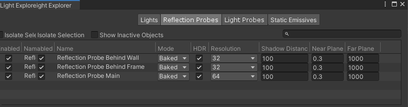
The next thing is the placement of lighting GameObjects in your Scene. Light objects include Directional, Point, Spotlight, and Area. Other GameObjects can have Materials with light Emission properties that make them glow and cast light onto other nearby objects. When object Materials are smooth and shiny and reflect other objects in the scene, you can precompute their reflections using Reflection Probes. To help you keep track of the various light sources in your scene, you can open the Light Explorer window, using Window | Rendering | Light Explorer.
It has tabs for Lights, Reflection Probes, Light Probes, and Static Emissives, as shown in the following screenshot:
Finally, you can add a Post-processing stack to the scene that produces a variety of camera and cinematic visual effects that make the scene look extra fantastic. We will explore each of these in the corresponding topics later in this chapter and use some of them in other projects in the book.
In this topic, we have taken an overview of the lighting settings and objects you can include in your VR projects. In establishing a lighting strategy for your project, you should start by first choosing a render pipeline. In this book, we are using URP. Then, you have a sequence of other decisions to make, including the Scene and Environment Lighting settings, Light GameObjects, and the Post-processing stack. We'll explore each of these in this chapter. But first, let's set up a demo scene that already includes examples of many of these lighting features.
Setting up our demo scene
To demonstrate lighting and rendering in Unity, we'll start the project for this chapter with an existing scene and observe the effect of removing or modifying certain lighting settings and GameObjects. When you start a new project from the Unity Hub using the Universal Render Pipeline template, it contains a default sample scene named SampleScene. For this chapter, we'll decompose the SampleScene rather than build up a new scene. (There is a risk that the SampleScene is subject to change in the future, so please adapt the instructions herein as needed.)
In the Scene, we'll create a tabbed menu panel with which you can interact within VR. I'm going to attach it to the LeftHand Controller, but if you prefer to place it as a dashboard panel in world space, feel free to do that. First, we'll adopt this SampleScene and add a VR Rig, then we'll disable lightmap baking so we can change lighting settings at runtime, and then we'll create a UI control panel for manipulating the lighting.
Using the SampleScene
Let's begin by modifying the default SampleScene. (If you have removed this scene or its assets, you can start a new URP project first). Follow these steps:
- Open the scene from the Project window by navigating to the Scenes/ folder and double-click on SampleScene.
- Save it as a new scene using File | Save As, and give it a name such as LightingDemos.
- Add a VR rig using GameObject | XR | Stationary XR Rig.
- Before I forget, minimize the near clipping plane by selecting the Main Camera GameObject (XR Rig/Camera Offset/Main Camera) and set Clipping Planes | Near to 0 (0.01).
- Position the rig to match the camera in the original sample scene, XR Rig | Transform | Position to (3.3, 0, 1.6), and Rotation to (0, 220, 0).
- Likewise, for development, set the camera height by setting XR Rig/Camera Offset| Transform | Y to 1.36.
- Lastly, align the Scene view by selecting Main Camera in the Hierarchy and choosing GameObject | Align View To Selected.
The scene we are working with can be seen in the screenshot that follows. I think it's a salute to the classic Website Under Construction pages! In the Hierarchy (not shown here), you will find it contains a Workshop Set GameObject containing the Ground, Drywall Panel, and Stud Frame. There's a group of Props, including the Workbench with tools. And for lighting, there's a Construction Light, Directional Light, Light Probe Group, Reflection Probes, and a Post-process Volume. Have a look at the following screenshot:

Our next step is to disable baked lighting so that we can manipulate more settings at runtime within VR.
Disabling baked lighting
For this exercise, we are going to completely disable baked lighting—that is, we'll use Realtime GI and not Mixed Lighting. Ordinarily, I would not recommend this, especially in VR projects, as it imposes a lot of runtime processing overhead that could slow the frame update rate and have a negative impact on your user experience. But for this project, we want to manipulate the lighting at runtime, frames-per-second be damned. To disable Baked GI, use the following steps:
- Open the Lighting settings window by going to Window | Rendering | Lighting.
- Select the Scene tab at the top of the window.
- Let's make a settings configuration asset unique to this scene by clicking the New Lighting Settings button (Unity 2020+).
- Uncheck the Baked Global Illumination checkbox.
OK—with that done, let's build a UI control panel where we can add toggle buttons and value sliders for controlling the lighting settings.
Creating a menu panel
Now, we'll create a world-space Canvas with a tabbed menu panel where we'll add UI controls to interact with various lighting settings in the scene. Be sure to use the XR menu item, not the non-XR Canvas one, so that the Canvas will contain the necessary Tracked Device Graphic Raycaster component and create an EventSystem with an XRUI Input Module component (as explained in Chapter 6, Canvasing World Space UI). Begin with the following steps:
- Create a new XR UI Canvas by selecting GameObject | XR | UI Canvas, and name it Menu Canvas.
- Set its Width and Height to 1024 and 768, respectively, and its Scale to 0.0005, 0.0005, 0.0005.
- Create a child panel for the tab by right-clicking Menu Canvas | UI | Panel, and name it Tabs.
- Set its Anchor Preset to top-stretch, Height: 150, Pos Y: -75, and pick a background Image | Color such as #417AAD with Alpha: 200.
- Create another child of Menu Canvas for the UI panels via Menu Canvas | UI | Panel, and name it Panels.
- Set itsAnchor Presettostretch-stretch, Top:150.
- Set itsImage | Color to a darker gray, such as #8C8C8C with Alpha 200.
To make it a hand palette menu, move the Menu Canvas to be a child of the LeftHand Controller, as follows (This step is optional. If you want, you can leave the Menu Canvas fixed in world space, especially if your VR device does not have two tracked hands.):
- In the Hierarchy, move the Menu Canvas GameObject to become a child of XR Rig / Camera Offset / LeftHand Controller.
- Set the Canvas Position to (0, 0, 0) and Rotation (0, 0, 0).
- On the LeftHand Controller we don't need its interactor, so uncheck the LeftHand Controller | XR Ray Interactor component's enabled checkbox (while leaving the LeftHand Controller object itself active).
- It may be convenient to align the Scene view by selecting the Menu Canvas in Hierarchy then choosing GameObject | Align View With Selected, then zoom back a little bit (using the mouse scroll wheel, or pressing Alt + right-mouse to zoom backward).
At this point, you should be able to press Play and see an empty menu palette attached to your left hand.
To add buttons in the tab bar, we'll make it a Horizontal Layout and add a Toggle Group of Toggle objects that act as buttons, using the following steps:
- With the Tabs panel selected in Hierarchy, select Add Component | Horizontal Layout Group.
- Set its Padding values to 5 (for all Left, Right, Top, Bottom, and Spacing), check the Control Child Size Width and Height checkboxes, and check the Child Force Expand Width and Height checkboxes (leaving the other checkboxes unchecked).
- Also, add a Toggle Group by selecting Add Component | Toggle Group.
- Create a child Toggle element by right-clicking the Tabs panel | UI | Toggle, and rename it Tab Button.
- Unfold the Toggle in Hierarchy, select its Background object, and modify it as follows: set the Anchor Preset to stretch-stretch, set Left/Right/Top/Bottom all to 0, and its Image | Color to a blue color (for example, #08158D).
- Unfold the Background in Hierarchy, select its child Checkmark object, and modify it as follows: rename it Selected, set the Anchor Preset to stretch-stretch, setLeft/Right/Top/Bottom all to 0, delete the contents of the Image | Source Image parameter, and choose an Image | Color with a lighter blue (for example, #4958CA).
- Then, select the Label GameObject and set its Text | Color to white, Alignment to Center, Middle, and check the Paragraph | Best Fit checkbox.
- Now, save the Tab Button as a prefab by dragging the Tab Button object from Hierarchy into the Project window Assets/Prefab/ folder.
Let's make a total of five buttons in the tab bar, as follows:
- In Hierarchy, duplicate the Tab Button four times (Ctrl + D) so that there are five buttons in the Tabs bar.
- Update the Label | Text for the buttons to read as Environ, Materials, Lights, Probes, and Post Process.
- Lastly, we want to make the toggle buttons a group so that only one can be selected at a time. Select a Tab Button in Hierarchy, and drag the parent Tabs panel onto the Toggle | Group field.
- Repeat step 3 for each of the tabs (tip: you can multi-select all five tab objects and assign the field in one step).
The resulting menu panel with the first tab button selected now looks like this:

Finally, we'll create five separate panels to contain the collection of UI controls for each of the menu tabs, and wire them up to the corresponding Tab Button. Use the following steps:
- In Hierarchy, select the Panels GameObject (child of Menu Canvas), right-click | UI | Panel, and name it Control Panel.
- Delete its Image component using right-click | Remove Component.
- Give it a vertical layout by selectingAdd Component | Vertical Layout Group.
- Set the Vertical Layout Group | Padding Left/Right/Bottom/Spacing to 50, setting the Top value to 20.
- Check the Control Child Size | Width and Child Force Expand | Width checkboxes, unchecking all the others.
- Now, under that panel, add a title by right-clicking Control Panel and select UI | Text, then rename it Title.
- Set its Height to 50, check the Paragraph | Best Fit checkbox, set Alignment to Middle, Center, and Color to blue (#08158D).
- Then, set the Text | Text to say Environmental Lighting.
- Duplicate this Control Panel four times (Ctrl + D), and modify their Label | Text accordingly, as follows:
- Materials and Shaders
- Light GameObjects
- Probes
- Post Processing Stack
- Finally, for each of the tab buttons, select Tab Button, then select Toggle | On Value Changed |+ to add an event action.
- Drag the corresponding Control Panel GameObject from Hierarchy onto the Runtime Only Object slot, and choose GameObject | SetActive from the function select list.
- Repeat steps 9-10 for the other four Tab Buttons.
- Note, as a toggle group, only one of the tabs, Toggles, can have Is On checked at a time. Likewise, you should set all the corresponding panels to not active except the current tab one.
- Save your scene withFile | Save.
If you play the scene now, the menu palette is attached to your left hand as you move your hand. Operate it using the right-hand controller to point, and click a tab button to open the corresponding controls panel.
You now have set up a copy of the SampleScene with an XR Rig, saved it as a new scene, disabled baked lightmaps, and created a Menu Canvas that will contain the control panels for operating the scene's lighting settings. The Menu Canvas has a tab bar with five buttons that enable the corresponding control panel UI. We're now ready to explore the lighting in the scene. We'll start by looking at environment lighting and adding UI controls for changing some of those settings.
Using environment lighting
The Environment lighting settings offer the ability to specify contributors to environmental illumination including a Skybox and Fog. A Skybox is a panoramic texture representing the sky that is drawn behind all objects in a scene as if at a far distance. We used the Wispy Skyboxes, for example, in previous chapters, and Skyboxes are discussed in more detail in Chapter 11, Using All 360 Degrees. More than rendering how the sky looks, with the Environment Lighting settings opened (using Window | Rendering | Lighting | Environment), you can specify if and how much the Skybox texture contributes to the Global Illumination and set its intensity level, as shown in the following screenshot:

For more details on using these and other settings in this window, consider the following pages from the Unity Manual:
- Outdoor lighting and scene setup— https://docs.unity3d.com/Manual/BestPracticeMakingBelievableVisuals6.html
- Lightmapping— https://docs.unity3d.com/Manual/Lightmappers.html
- Scripting API: RenderSettings— https://docs.unity3d.com/ScriptReference/RenderSettings.html
Let's add the first two controls to the control panel—a Skybox Toggle checkbox and an Intensity Multiplier Slider that lets you interactively modify these values while in VR. As we go, we'll also save this UI as a prefab so that we can reuse this work elsewhere in this chapter.
Environment lighting source
To demonstrate the effects of some of these settings in your VR scene, we'll add controls to our menu palette that modify environmental lighting throughan Environment
LightingControls script. Let's create that script now and build it out as we go. Start with the following steps:
- Create an empty GameObject in theHierarchyroot, namedRender Controller, by selecting GameObject | Create Empty.
- Reset itsTransformwithright-click | Reset.
- Create a new script namedEnvironmentLightingControlsand add it to the Render Controller.
Using this script and a couple of UI prefabs that we'll create next, we will control the Environment Light setting including the Skybox and Fog, and see how it looks in VR. The script uses Unity's RenderSettingsapplication programming interface (API) class (https://docs.unity3d.com/ScriptReference/RenderSettings.html). Let's start with a way to toggle the Skybox on and off. Edit the EnvironmentLightingControls script, as follows:
using UnityEngine;
using UnityEngine.Rendering;
using UnityEngine.UI;

public class EnvironmentLightingControls : MonoBehaviour
{
    public Toggle useSkyboxToggle;

    public bool UseSkybox
    {
        get => (RenderSettings.ambientMode == AmbientMode.Skybox);
        set
        {
            RenderSettings.ambientMode = (value) ?
               AmbientMode.Skybox : AmbientMode.Flat;
        }
    }

    private void Start()
    {
        useSkyboxToggle.isOn = UseSkybox;
    }
}
Since we're interested in using the RenderSettings API, we add the using UnityEngine.Render; line.
Although we want the user to simply toggle the Skybox on or off, Unity actually offers three options for the Environment Lighting Source (as you have seen in the previous screenshot): Skybox, Gradient, and Color. So, our plan is that, when the Skybox is turned off, we'll switch the Source from Skybox to Color. In the code, I declare a Boolean property, UseSkybox. When UseSkybox is referenced, it returns either true or false, whether RenderSettings.ambientMode is presently AmbientMode.Skybox or not. Likewise, when UseSkybox is set, we set the RenderSettings.ambientMode to AmbientMode.Skybox or AmbientMode.Flat (aka Color). In the Start() function, we initialize the UI toggle switch according to the default RenderSettings value when the project is built.
Now, let's add the toggle UI element to the menu panel. Create a new toggle switch in the menu panel by following these steps:
- In theHierarchy, on theMenu Canvas / Panelsselect the (first)Control Panel, which is designated for Environmental Lighting.
- Right-click, then selectControl Panel | UI | Toggle and name itSkybox Toggle.
- Set itsRect Transform | Heightto50.
- Unfold the Skybox Toggle in Hierarchy and, on its Label, set Anchor Preset: top-left, Pos (0, 0, 0), Width, Height: (450, 50), Font Size: 38, Color: White, Alignment: Right.
- For its Text, write Use Skybox.
- Select the Background child of Skybox Toggle, set Anchor Preset: top-right, Pos (-200, 0, 0), Width, Height: (50, 50).
- And, for the Background own child Checkmark, set Width, Height: (50, 50).
Now, we can connect the toggle to the UseSkybox property in the script we wrote, as follows:
- Select the Skybox Toggle, and in Inspector, select Toggle | On Value Changed | + to add an event action.
- Drag the Render Controller object from Hierarchy onto the Object slot.
- Then, from the Function dropdown, select EnvironmentLightingControls | UseSkybox.
- Lastly, select the Render Controller object in Hierarchy, and drag the Skybox Toggle object from Hierarchy onto the Environmental Lighting Controls | Use Skybox Toggle slot.
- Save with File | Save.
If you press Play, then in VR you can point and click on the checkbox to disable or enable the Skybox environment lighting.
Let's save this Toggle object as a prefab so we can reuse it for other properties, as follows:
- Select the Skybox Toggle from Hierarchy.
- Drag it into the Assets/Prefabs/ folder in the Project window.
- In the Assets folder, rename the prefab ToggleUI.
Next, we will add a UI slider to change the environment light intensity.
Adding Environment Light Intensity
To control the Environment Light Intensity Multiplier, we'll add a slider to the menu panel. The Intensity only applies when the light source is a Skybox, so this slider will only be enabled while the Use Skybox toggle is checked. Let's add it to the control script by editing EnvironmentLightingControls. The new lines of code are highlighted in bold in the following code block:
public class EnvironmentLightingControls : MonoBehaviour
{
    public Toggle useSkyboxToggle;
    public Slider skyboxIntensitySlider;
    public Text skyboxIntensityText;

    public bool UseSkybox
    {
        get => (RenderSettings.ambientMode == AmbientMode.Skybox);
        set
        {
            RenderSettings.ambientMode = (value) ?
                AmbientMode.Skybox : AmbientMode.Flat;
            skyboxIntensitySlider.interactable = value;
            skyboxIntensityText.gameObject.SetActive(value);
        }
    }

    public float SkyboxIntensity
    {
        get => RenderSettings.ambientIntensity;
        set
        {
            RenderSettings.ambientIntensity = value;
            skyboxIntensityText.text = value.ToString("F1");
        }
    }

    private void Start()
    {
        useSkyboxToggle.isOn = UseSkybox;
        skyboxIntensitySlider.value = SkyboxIntensity;
    }
}
The script adds a new float SkyboxIntensity property that can get and set the current RenderSettings.ambientIntensity value. In addition to the slider UI element, it also references a Text object that displays the current intensity multiplier value on the menu panel. We'll let the intensity value range from 0 to 3. Let's create these UI elements with the following steps:
- In the Hierarchy, on the same Environmental LightingControl Panel, right-click | Create Empty and rename itIntensity Slider.
- Add a child Slider UI element using right-click | UI | Slider.
- On the Slider, set Anchor Preset: middle-right, Pos (-200, 0, 0), Width, Height: (350, 50).
- Under the parent Intensity Slider, add a child Text element using right-click | UI | Text, rename it Label.
- On the Label, set its Text to read Skybox Intensity Multiplier, and set Anchor Preset: middle-left, Pos (240, 0, 0), Width, Height: (450, 50), Font Size: 38, Color: white, Align: Right.
- Under the Slider / Handle Slide Area, find the Handle object, then right-click | UI | Text. Set its Pos (35, 42, 0), Font Size: 38, Color: white, Align: Center, Horizontal/Vertical Overflow: Overflow.
- On the Slider, set the Min Value to 0 and Max Value to 3.
- Connect the slider to the script. On the Slider, select Slider | On Value Changed | +, drag theRender Controllerobject fromHierarchyonto theObjectslot, and set the function to EnvironmentLightingControls | SkyboxIntensity.
- Lastly, select theRender Controllerobject inHierarchy, and drag theSliderelement fromHierarchyonto theEnvironmental Lighting Controls | Skybox Intensity Slider slot.
- Then, drag the Handle's Text object onto the Skybox Intensity Text slot.
- Let's also save this slider as a prefab so that we can use it for other properties. Drag the parentIntensity SliderfromHierarchyinto theProjectAssets/Prefabs/folder and rename the prefabSliderUI.
- Save withFile | Save.
The following screenshot shows the Menu Canvas hierarchy we just created:

If you press Play, then in VR you can modify the Skybox intensity with the slider (when the Use Skybox functionality is enabled). The following screenshot shows a capture of the scene in VR with the Canvas Menu on the Environ tab and the Skybox Intensity Multiplier pushed up to 1.9:

Next, we'll add a toggle for disabling or enabling environmental Fog.
Adding a Fog effect
Let's add one more toggle for the environment lighting. The Fog added to the scene will make objects in the distance appear washed out, improving the sense of depth and realism, especially in outdoor scenes. You have a number of Fog properties available, including Color, Mode, and Density. We'll simply toggle the Fog off and on to see its effects in VR. Edit the EnvironmentLightingControls script by adding the following code:
    public Toggle enableFog;

    public bool EnableFog {
        get => RenderSettings.fog;
        set => RenderSettings.fog = value;
    }
And in Start(), initialize the Toggle state, as follows:
enableFog.isOn = EnableFog;
To add this toggle to our panel, we can use the ToggleUI prefab we just created, as follows:
- From the Project window Assets/Prefabs/ folder, drag the ToggleUI prefab into Hierarchy as the bottom child of the Control Panel we are working on (sibling of the Intensity Slider).
- Rename it Fog Toggle.
- Unfold Fog Toggle, and modify the Label | Text to read Enable Fog.
- On the Fog Toggle | Toggle component, drag the Render Controller onto the On Value Changed | Object field, and select EnvironmentLightingControls | EnableFog.
- Lastly, select the Render Controller and drag the Fog Toggle game object from Hierarchy onto the Environment Lighting Controls | Enable Fog slot.
The following screenshot shows the Environment Lighting Controls component with its current properties:

Press Play. You can now see the effect of disabling and enabling Fog in your scene. The UI menu panel we just created now looks like this (I improved the panel titles' color in my version):

Environmental lighting is usually baked into lightmaps but for this scene, it's not, so we can control it at runtime. In this section, we created the first Control Panel in the Menu Canvas, with a checkbox to Use Skybox and a value slider for the Skybox Intensity Multiplier. We also added a checkbox for the Fog. With these controls (and feel free to add others on your own), you can experience the effect of modifying these Environment Light settings inside VR.
Next, we'll take a look at the effect of PBR materials and shader parameters on the realism of objects in the scene.
Using PBR materials and URP Shaders
3D objects can be rendered simplistic, such as a cube with flat-shaded faces, or very realistically, such as the same cube as a realistic wooden crate. This magic is performed with PBR materials and advanced Shaders.
A 3D object in Unity consists of a geometry mesh that defines the points, edges, and faces of the object, forming a surface that can then be rendered to appear as a solid object. Each object has a Renderer component that specifies the properties and behavior of this particular object rendered in the scene. It includes references to any Materials that will be applied to the object. A Material is an asset that specifies a specific Shader script that drives the actual work of drawing the object on the screen. You can learn more about all of this in the Unity Manual and Unity Learn sites, among many other resources. The following web pages provide more information:
- Best Practices Guide: Making Believable Visuals: Modeling— https://docs.unity3d.com/Manual/BestPracticeMakingBelievableVisuals4.html
- Best Practices Guide: Making Believable Visuals: Shading— https://docs.unity3d.com/Manual/BestPracticeMakingBelievableVisuals5.html
- Unity Manual: Shadows— https://docs.unity3d.com/Manual/Shadows.html
In this book, we focus on the URP and thus are limited to the Shaders compatible with that RP. Ordinarily, we use the default Lit shader in the Materials we are using because it offers a lot of variety, options, and settings while being quite efficient at runtime. Shaders are small programs that arecompiledto run in the GPU. They process your 3D vectors and polygons (triangles), prepared by the game engine on the CPU, along with lighting information, texture maps, and other parameters, to generate pixels on the display.
Unity comes with a rich set of Shaders. The Universal Render Pipeline/Lit Shader we've been using throughout this book is a powerful and optimized one that supports textures, normal maps, occlusion maps, emission maps, specular highlights, reflections, and more. And, depending on which features of the particular shader you actually use in a material, Unity will compile a highly optimized shader variant file to run the processing in the GPU.
For example, consider the HardHat_Mat material used in our scene for the hardhat prop, as shown in the following screenshot:

You can see this Material uses the Universal Render Pipeline/Lit shader. It selects the Metallic Workflow Mode with an Opaque surface. The surface properties include a Base Map texture, which is the basic color texture (Albedo) of the model. It also has a MetallicMaptexture that controls shininess, a NormalMap that provides the appearance of bumps and grooves on the surface, and an Occlusion Map that further enhances the realism by accenting surface shadows associated with occlusion. You can examine the individual texture images by clicking one of the texture map chips and viewing the asset in the Inspector.
For this project, we will create slider controls that let you adjust the properties of materials, including the following:
- Smoothness factor (0 to 1)
- Normal scaling factor (-3 to 3)
- Occlusion factor (0 to 1)
To begin, create a new script named MaterialsControls on the Render Controller game object. Then, edit it as follows. I'll begin with the first part of the script, where we declare a set of public variables that reference the UI Slider (and the handle Text) for each smoothness, normal scaling, and occlusion factor. We also have a Renderer list that you'll populate in the Inspector, and which will be manipulated by the script. When you modify a factor value at runtime with the menu panel, the script will set this factor on all the Materials in the given list, like this:
using System.Collections;
using System.Collections.Generic;
using System.Linq;
using UnityEngine;
using UnityEngine.UI;

public class MaterialsControls : MonoBehaviour
{
    public Slider smoothnessSlider;
    public Text smoothnessText;
    public Slider normalSlider;
    public Text normalText;
    public Slider occlusionSlider;
    public Text occlusionText;

    public List<Renderer> renderers = new List<Renderer>();
And in Start(), I'll initialize the sliders to a normal value of 1, like this:
    private void Start()
    {
        smoothnessSlider.value = 1f;
        normalSlider.value = 1f;
        occlusionSlider.value = 1f;
    }
Next, I have separate float type properties for Smoothness, Normal, and Occlusion, with their corresponding get and set methods. Internally, we keep a cache of the current values (using the underscore prefix-naming convention to denote it's a private variable). As we did in the previous section, when you set one of the values, we also update its Text display on the slider, as illustrated in the following code block:
    private float _smoothness;
    private float _normal;
    private float _occlusion;

 public float Smoothness {
 get => _smoothness;
 set {
     SetFloatProperty("_Smoothness", value);
     smoothnessText.text = value.ToString("F2");
     }
 }

 public float Normal {
 get => _normal;
 set {
     SetFloatProperty("_BumpScale", value);
     normalText.text = value.ToString("F2");
     }
 }

 public float Occlusion {
 get => _occlusion;
 set {
     SetFloatProperty("_OcclusionStrength", value);
     occlusionText.text = value.ToString("F1");
     }
 }

 private void SetFloatProperty(string name, float value)
 {
 for (int i = 0; i < renderers.Count; i++)
  {
    renderers.ElementAt(i).material.SetFloat(name, value);
  }
 }
}
The sliders will send a value to the corresponding property. The set method calls our private SetFloatProperty function that loops through all the renderers we want to modify and then sets the value using the material.SetFloat call.
When getting and setting property values within a shader, you can only reference it indirectly with its name string. To discover what the name is of a specific property, you can open the Shader script to find it. For example, on the HardHat_Mat material, use the three-dot context menu to select Edit Shader, which opens the file in your text editor. The lines of code that I referenced to find the _Smoothness, BumpScale, and _OcclusionStrength properties look like the following in the shader file (this is just for your information):
_Smoothness("Smoothness", Range(0.0, 1.0)) = 0.5
_BumpScale("Scale", Float) = 1.0
_OcclusionStrength("Strength", Range(0.0, 1.0)) = 1.0
Save the script. Now, back in Unity, we want to provide a set of object renderers to the component, as follows:
- With Render Controller selected in Hierarchy, add the MaterialsControls script (if it's not already a component).
- In Inspector, set the Materials Controls | Renderers | Size to 5.
- Drag the Safety Hat game object from Hierarchy (Example Assets / Props / Workbench) onto the Element 0 slot.
- Drag the Jigsaw game object onto Element 1.
- Drag the Stud game object onto Element 2.
- Drag the Hammer game object onto Element 3.
- Drag the Bench Top game object onto Element 4.
We can now add the sliders to the Control Panel in our menu, using the following steps:
- In Hierarchy, find the second Control Panel under your Menu Canvas corresponding to the Materials tab button.
- From the ProjectAssets/Prefabs folder, drag the SliderUI prefab into Hierarchy as a child of the Control Panel.
- Rename it Smoothness Slider.
- Change its Label | Text to say Smoothness.
- Select its Slider object and select Slider | On Value Changed | + to add an event action, drag the Render Controller onto the Object slot, and select the MaterialsControls | Smoothness function.
- Then, with the Render Controller selected in Hierarchy, drag this Slider object onto the Materials Controls | Smoothness Slider slot.
- Then, drag the handle Text object (found under Slider / Handle Slide Area / Handle /) onto the Smoothness Text slot.
- Repeat Steps 2-7 for the Normal and Occlusion properties.
Note that the Slider range (Min Value, Max Value) for Smoothness and Occlusion are (0, 1), but for Normal, make the range (-3, 3).
With this menu panel implemented, you can now Play the scene and see the effect of modifying these three properties at runtime in VR. The following screenshot shows the Normal scale being greatly exaggerated at 3 (while Use Skybox lighting is disabled) on the wooden Stud, Bench Top, and Jigsaw objects:

The UI menu panel we just created now looks like this:

In this section, we considered how PBR materials contribute to the realism of objects in a scene. With our interactive control panel, you created sliders for modifying the Smoothness, Normal factor, and Occlusion contributions of the corresponding texture map for a set of materials. In the process, you also learned how to access Shader properties via C# script.
Next, we'll look at adding Light GameObjects for local illumination of your scene and using light emission materials.
Using Light objects and Emission surfaces
For indoor and local lighting, you will want to add Light objects to your scene. These are GameObjects that are not rendered themselves as meshes but rather emit light in a specific pattern, such as a cone (for example, a Spot light), sphere (for example, a Point light), or unidirectionally (for example, a Directional light). Also, you can specify individual objects to illuminate from their inside by assigning Materials with Emission properties. For more information on designing and using light objects, see the following links:
- Best Practices Guide: Making Believable Visuals: Indoor and local lighting—https://docs.unity3d.com/Manual/BestPracticeMakingBelievableVisuals7.html
- Unity Manual: Types of light— https://docs.unity3d.com/Manual/Lighting.html
- Emission— https://docs.unity3d.com/Manual/StandardShaderMaterialParameterEmission.html
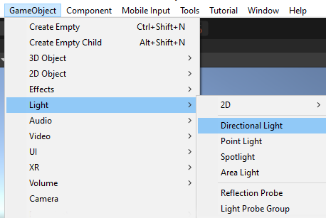
Lights can be added to your scene using the GameObject | Light menu, as shown in the following screenshot:
In our scene in this project, we have two lights and one Emission surface. First, there is a Directional Light, which you'd get when you create a New Scene. Directional lights cast in the same direction everywhere in the scene, like the sun illuminates the Earth because it's very far away. As you can see from its properties shown in the following screenshot, the Directional Light in our scene is set at an angle in the sky, with an Intensity value of 2, and casts Soft Shadows:

Also in the scene is a Construction Lamp prop (found in Example Assets / Props) that includes a Spot Light (standing behind the studded wall). In the following screenshot, the Spot Light is selected in Hierarchy, and you can see the Scene top-down view depicting the Range and Inner/Outer Spot Angles of the light. It's a bright light with an Intensity value of 12:

Within the Construction Light model is a lightbulb (Light_Bulbs_Low) that has a LightBulb_Mat material with a white emission that makes the lightbulb appear to be glowing.
For this project, we will create slider controls that let you adjust the following light object properties:
- Directional angle (x axis) (0 - 180)
- Directional intensity (0 - 2)
- Spot intensity (0 - 24)
- Spot Bulb emission toggle
To begin, create a new script, named LightsControls, on the Render Controller game object. Then, edit it as follows. We can begin with the first part of the script, where we declare a set of public variables that reference a UI Slider for the directional angle, directional intensity, and spot intensity, and a UI Toggle for the Spot Bulb object's emission property. We also declare variable references to the GameObjects themselves. Have a look at the following code block:
using UnityEngine;
using UnityEngine.UI;

public class LightsControls : MonoBehaviour
{
    public Slider directionalAngleSlider;
    public Slider directionalIntensitySlider;
    public Slider spotIntensitySlider;
    public Toggle bulbEmissionToggle;

    public Light directionalLight;
    public Light spotLight;
    public Renderer spotBulb;

    private Text directionalAngleText;
    private Text directionalIntensityText;
    private Text spotIntensityText;

    private bool _bulbEmission;
    private Color _emissionColor;
This time around, I've declared the Text object references for the slider handles as private, and find them at runtime in Start(). Lastly, I declare a _bulbEmission Boolean that says when we've disabled or enabled the bulb emission property. To turn off the emission, I will set its Emission Color to black, and restore its original color (_emissionColor) when enabled. The Start() function is written as follows, initializing these variables:
    private void Start()
    {
        directionalAngleText = directionalAngleSlider.
              GetComponentInChildren<Text>();
        directionalIntensityText = directionalIntensitySlider.
              GetComponentInChildren<Text>();
        spotIntensityText = spotIntensitySlider.
              GetComponentInChildren<Text>();

        directionalAngleSlider.value = DirectionalAngle;
        directionalIntensitySlider.value = DirectionalIntensity;
        spotIntensitySlider.value = SpotIntensity;

        _emissionColor = spotBulb.material.
              GetColor("_EmissionColor");
        _bulbEmission = (_emissionColor != Color.black);
        bulbEmissionToggle.isOn = BulbEmission;
    }
Now, we can add the four properties we are controlling, implemented with their get and set methods. The DirectionalAngle property simply modifies the object's Transform. The DirectionalIntensity property modifies the Light component property. Likewise for SpotIntensity, as illustrated in the following code block:
    public float DirectionalAngle
    {
        get => directionalLight.transform.localEulerAngles.x;
        set
        {
            Vector3 angles = directionalLight.transform.
                                              localEulerAngles;
            angles.x = value;
            directionalLight.transform.localEulerAngles = angles;
            directionalAngleText.text = value.ToString("F0");
        }
    }

    public float DirectionalIntensity
    {
        get => directionalLight.intensity;
        set
        {
            directionalLight.intensity = value;
            directionalIntensityText.text = value.ToString("F1");
        }
    }

    public float SpotIntensity {
        get => spotLight.intensity;
        set
        {
            spotLight.intensity = value;
            spotIntensityText.text = value.ToString("F1");
        }
    }

    public bool BulbEmission
    {
        get => _bulbEmission;
        set
        {
            spotBulb.material.SetColor("_EmissionColor",
                value ? _emissionColor : Color.black);
            _bulbEmission = value;
        }
    }
We can now add the sliders to the Control Panel in our menu, using the following steps:
- In Hierarchy, find the third Control Panel under your Menu Canvas corresponding to the Lights tab button.
- From the ProjectAssets/Prefabs folder, drag the SliderUI prefab into Hierarchy as a child of the Control Panel.
- Rename it DirectionalAngle Slider.
- Change its Label | Text to say Directional Light Angle.
- Set the Slider | Min Value and Max Value to (0, 180).
- Select its Slider object and select Slider | On Value Changed | + to add an event action.
- Drag the Render Controller onto the Object slot.
- Select the LightsControls | DirectionalAngle function.
- Then, with the Render Controller selected in Hierarchy, drag this Slider object onto the Materials Controls | Directional Angle Slider slot.
- Repeat steps 2-7 for the DirectionalIntensity and SpotIntensity properties.
Note that the Slider range (Min Value, Max Value) for intensity is (0, 1) but for the light angle, make the range (0, 180).
Also, add the toggle for the lightbulb emission, as follows:
- From the Project window Assets/Prefabs/ folder, drag the ToggleUI prefab into Hierarchy as the bottom child of the Control Panel we are working on (sibling of SpotIntensity Slider).
- Rename it Emission Toggle.
- Unfold Emission Toggle, and modify the Label | Text to read Enable Bulb Emission.
- On the Emission Toggle | Toggle component, drag the Render Controller onto the On Value Changed | Object field, and select LightsControls | BulbEmission.
- Lastly, select the Render Controller and drag the Emission Toggle GameObject from Hierarchy onto the Light Controls | Bulb Emission slot.
With this menu panel implemented, populate the lights GameObjects as follows:
- Select Render Controller in Hierarchy.
- Drag the Directional Light onto the Lights Controls | Directional Light slot.
- Drag the Spot Light (found under Props / Construction Light Low) onto the Spot Light slot.
- Drag the Light_Bulbs_Low object (which has an Emission material) onto the Spot Bulb slot.
You can now Play the scene and see the effect of modifying these properties at runtime in VR. Notice when you change the directional light angle, in addition to the shadows moving, you can actually see the "sun" moving in the sky. This is because in the Lighting settings window, Sun Source is set to the Directional Light game object, and Unity renders a sun-like blob in the sky at its location. Also, notice that when you disable the Bulb Emission, the lightbulbs are still rendered but their glow is turned off. The UI menu panel we just created now looks like this:

In this section, we saw how the Light GameObject can be used to contribute to the lighting of a scene. We created interactive controls for the Directional Light angle and intensity, and one for the Spot Light intensity. We also learned about the Emission property of Materials—in this case, the lightbulbs glow.
Next, we'll look at some more advanced objects you can add to the scene that are especially important when you are baking lightmaps: using Light Probes and Reflection Probes.
Using Light Probes and Reflection Probes
For non-static GameObjects to receive global illumination, you need to have Light Probes distributed in the Scene. These provide high-quality lighting for moving (dynamic) objects. Light Probes are positions in the scene where information is captured about the light that is passing through the empty space in your Scene. This information is baked similar to lightmaps and then used when the scene is rendered at runtime to approximate the indirect light hitting dynamic objects, based on proximity to the Light Probes nearest to that object. For more information on Light Probes, see https://docs.unity3d.com/Manual/LightProbes.html and the corresponding subpages.
A group of Light Probes is defined with a single Light Probe Group GameObject. In our scene, the Light Probe Group contains dozens of probes. As shown in the following screenshot, the Light Probe Group is selected in Hierarchy, the Edit Light Probes button is pressed in the Inspector, and one of the probes is selected in the Scene window (shaded blue), with its Selected Probe Position (X, Y, Z) location shown in the Inspector:

Another kind of probe, a Reflection Probe, provides an efficient means of calculating realistic reflections on object surfaces, giving a sense of connection and cohesion to objects in the scene. It turns out that for the human eye to obtain this perceptual effect, this does not require 100% visual accuracy and detail in the reflections. A low-resolution reflection map can be baked beforehand and used in rendering. To achieve this, you can insert Reflection Probe GameObjects into the scene that will capture a panoramic view (cubemap) of the surroundings from that viewpoint. When a reflective object passes near to a probe, the sampled visual data is used for the reflection map. For more information on Reflection Probes, see https://docs.unity3d.com/Manual/ReflectionProbes.html and the corresponding subpages.
You'll find in the Hierarchy that our scene contains three Reflection Probes. The one named Reflection Probe Main is positioned in the middle of the construction space. Shown in the following screenshot, it looks like a perfectly reflective ball hovering in space. Of course, it's not itself rendered in the scene but is used to provide approximate reflections in nearby shiny objects:

For this project, we will add two Toggle controls to enable or disable the Light Probes and Reflection Probes. To begin, create a new script, named ProbesControls on the Render Controller GameObject. Then, edit it as follows (the entire script is shown because it's relatively short):
using UnityEngine;
using UnityEngine.UI;

public class ProbesControls : MonoBehaviour
{
    public Toggle lightProbesToggle;
    public Toggle reflectionProbesToggle;

    public GameObject lightProbes;
    public GameObject reflectionProbes;

    public bool LightProbes
    {
        get => lightProbes.activeInHierarchy;
        set => lightProbes.SetActive(value);
    }

    public bool ReflectionProbes
    {
        get => reflectionProbes.activeInHierarchy;
        set => reflectionProbes.SetActive(value);
    }

    private void Start()
    {
        lightProbesToggle.isOn = LightProbes;
        reflectionProbesToggle.isOn = ReflectionProbes;
    }
}
I provide public variables for the Toggle UIs and the probes' GameObject. The LightProbes and ReflectionProbes Boolean properties with the get and set methods simply SetActive the given GameObjects in the scene. Drag the Light Probes and Reflection Probes objects onto the corresponding component slots.
We can now add the toggles to theControl Panelin our menu, using the following steps:
- InHierarchy, find the fourth Control Panelunder yourMenu Canvascorresponding to the Probes tab button.
- From theProjectwindowAssets/Prefabs/folder, drag theToggleUIprefab intoHierarchyas the bottom child of the Control Panel.
- Rename itLight Probes Toggle.
- UnfoldLight Probes Toggle, and modify theLabel | Textto readEnable Light Probes.
- On theLight Probes Toggle | Togglecomponent, drag theRender Controlleronto theOn Value Changed | Objectfield, and select ProbesControls| LightProbes.
- Then, select theRender Controllerand drag theLight Probes Toggle GameObject fromHierarchyonto theProbes Controls | Light Probesslot.
- Repeat steps 2-6 for the ReflectionProbes property.
The UI menu panel we just created now looks like this:

With this menu panel implemented, populate the Lights GameObjects as follows:
- Select Render Controllerin Hierarchy.
- Drag theLight Probes Group GameObject from Hierarchyonto theProbes Controls | Light Probesslot.
- Drag the Reflection Probes GameObject from Hierarchy onto the Reflection Probes slot.
You can now Play the scene and see the effect of modifying these properties at runtime in VR. The following screenshot shows the scene side by side, with the probes enabled (on the left), and all the Light Probes and Reflection Probes disabled (on the right):

In this section, you learned about using Light Probes to add environment lighting to dynamic objects, and Reflection Probes to add environment reflections to shiny surfaces. We added checkbox controls that let you turn these on and off in the scene at runtime to see their effect.
Next, we'll look at how post-processing effects can be used to enhance the realism and cinematic effects of your scenes.
Enhancing your scenes with post-processing effects
So, we've seen how the Render Pipeline can use environment lighting, PBR Materials, Light GameObjects, and Probes to render realistic views of your scene. But wait! There's more! You can add post-processing effects to the fullscreen camera buffer image before it appears on the screen. Post-processing effects are often used to simulate the visual properties of a physical camera and film. Examples include Bloom (fringe lighting extending the border of extremely bright light), Color Grading (adjusts the color and luminance of the final images, like an Instagram filter), and Anti-aliasing (removing jaggy edges). You can stack a series of available effects that are processed in sequence.
For example, the Vignette effect darkens the edges of the image and leaves the center brighter. In VR, during a fast-paced scene (such as a racing game or roller coaster), or when teleporting, using a Vignette can help reduce motion sickness. On the other hand, some other effects, includingLens Distortion, Chromatic Aberration, and Motion Blur are best avoided in VR.
For more information on creating and using post-processing effects, see the following links:
- Best Practices Guide: Making Believable Visuals: Understanding post-processing— https://docs.unity3d.com/Manual/BestPracticeMakingBelievableVisuals8.html
- Unity Manual: Post-processing (and its subpages)—https://docs.unity3d.com/Manual/PostProcessingOverview.html
- Post-processing in the Universal Render Pipeline— https://docs.unity3d.com/Packages/[email protected]/manual/integration-with-post-processing.html
In our scene, the post-processing effects are defined on a GameObject in the Hierarchy named Post-process Volume, which contains a Volume component that has several effects—namely, Tonemapping, Bloom, and Vignette. Its Inspector is shown in the following screenshot:

For this project, we will dynamically instantiate ToggleUI checkboxes for each post-processing effect we find on the Volume. To begin, create a new script named
PostProcessControls on the Render Controller GameObject. Then, edit it as follows (the entire script is shown because it's relatively short):
using System.Collections.Generic;
using System.Linq;
using UnityEngine;
using UnityEngine.Rendering;
using UnityEngine.UI;

public class PostProcessControls : MonoBehaviour
{
    public Transform uiPanel;
    public GameObject togglePrefab;
    public Volume postProcessVolume;

    private VolumeProfile profile;
    private List<VolumeComponent> components;
    private List<Toggle> toggles = new List<Toggle>();

    private void Start()
    {
        profile = postProcessVolume.profile;
        components = profile.components;

        for (int i = 0; i < components.Count; i++)
        {
            GameObject go = Instantiate(togglePrefab, uiPanel);
            Toggle toggle = go.GetComponent<Toggle>();
            int index = i;
            toggle.onValueChanged.AddListener((value) =>
                { components.ElementAt(index).active = value; });
            Text text = go.GetComponentInChildren<Text>();
            text.text = components.ElementAt(i).name;
            toggles.Add(toggle);
        }
    }
}
In the script, we declare a public variable for the uiPanel control panel, within which we'll create the UI toggles. There's a reference to the togglePrefab object to instantiate and a reference to the post-processing Volume component in the Scene. The only function is Start(), where we grab the list of VolumeComponent instances from the Volume. Then, for each effect component, we create a ToggleUI instance.
For each toggle, we display the post-processing VolumeComponent name in the Text label. We then define an event action for onValueChanged—when the user checks or unchecks the toggle, it will set the active component to true or false.
Now, in Unity, we don't need to manually add any UI elements to the Control Panel because the script will do this. Populate the variable values as follows:
- In Hierarchy, select the Render Controller.
- From Hierarchy, drag the last (fifth) Control Panel GameObject under the Menu Canvas / Panels / onto the Post Process Controls | UI Panel slot.
- From the ProjectAssets/Prefabs folder, drag the ToggleUI prefab onto the Post Process Controls | Toggle Prefab slot.
- From Hierarchy, drag the Post-process Volume GameObject onto the Post Process Controls | Post Process Volume slot.
With this menu panel implemented, you can now play the scene and see the effect of toggling these effects at runtime in VR. The following screenshot shows the Control Panel populated at runtime with the post-processing effects stack (Volume components) in this scene, where Bloom is disabled. You'll notice in this screenshot that in the background, the wall studs are illuminated by the construction lamp, but are not Bloom, as they were in screenshots earlier in this chapter:

In this section, you learned how this scene is using post-processing Volume effects, including Tonemapping, Bloom, and Vignette. You also learned how to access the components for each of these effects from C#. We added checkbox controls that let you turn each post-processing component on and off to see their effect at runtime in VR.
Summary
In this chapter, we explored how to create visual realism in your VR scenes using environmental lighting, Light GameObjects, emissive materials, post-processing, and other tools included with Unity. We started by walking through a lighting strategy for configuring and enhancing your scenes, using decision trees and best practices suggested in the Unity Best Practices Guides. Then, using a sample scene, you created a menu palette with control panels for manipulating various lighting settings in the scene at runtime, while in VR.
You learned about the Lighting settings window, Global Illumination baking, and the Environment light settings, adding UI controls to modify the Skybox and Fog contribution to lighting. Then, you learned about PBR materials for creating realistic 3D objects in the scene, adding UI controls to modify the Material properties of various texture maps. Next, you learned how to use Light GameObjects and Emission Material properties to add local lighting in the scene, and explored this with UI controls to modify the Directional Light and the construction Spot Light in the scene, plus the Emission property for the lightbulb. You saw how lighting can be further enhanced with Light Probes, for pre-calculating lighting at specific locations in the scene for dynamic objects, and Reflection Probes, for pre-calculating reflections on shiny surfaces. Lastly, you learned about Post-processing Volumes that add cinematic effects and enhancements to the camera image before it is drawn on your device screen, dynamically adding UI checkbox controls to your menu panel to turn on and off individual effect components at runtime in VR.
Along the way, you learned some more advanced C# coding techniques, including class properties (with getter and setter methods), using the specific Unity namespace API including UnityEngine.Rendering, accessing material and shader properties, using List collections, and using lambda expressions.
In the next chapter, we'll build a real VR application, a paddle-ball game that shoots fireballs in sync with music beats that you try to hit back into a target. You'll learn more about the Unity physics engine, particle effects, and C# GameObject pooling, as well as other techniques important for VR development.