Patterning and mirroring in SolidWorks are great tools to help you improve your efficiency. SolidWorks software provides many powerful pattern types that also help you accomplish design tasks. In addition to the different types of patterns, there are options that enable functionality that you may not have considered. A solid understanding of patterning and mirroring tools is necessary to be able to build the maximum amount of parametric intelligence into your models.
You can use both pattern and mirror functions in sketch mode, although sketch patterns are not a preferred choice. The distinction between patterning and mirroring in sketch mode is important when it comes to sketch performance.
Performance
Although there are many metrics for how software performs, in SolidWorks, the word performance means the same thing as speed. Sketch patterns have a very adverse effect on speed, and do not offer the same level of control as feature patterns.
You might hear a lot of conflicting information about which features are better to use in different situations. Users coming from a 2D background often use functions such as sketch patterning because it's familiar, without questioning whether there is a better approach. When in doubt, you can perform a test to determine which features work best for a given situation.
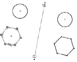
In this test, I made a series of 20-by-20 patterns using circles, squares, and hexagons. The patterns are both sketch patterns and feature patterns, and I created them with both Verification on Rebuild and Geometry Pattern turned on and off. Verification on Rebuild is an error checking setting that you can access through Tools
Table 8.1 shows the rebuild times (in seconds) of solid geometry created from various types of patterns as measured by Feature Statistics (found at Tools
Generally, the number of faces and sketch relations being patterned has a significant effect on the speed of the pattern. The sketch pattern times are taken for the entire finished model, including the sketch pattern and a single extrude feature, using the sketch with the pattern to do an extruded cut. The sample parts are on the CD-ROM for reference. Look for the filenames beginning with Reference1 through Reference7.
Table 8.1. Pattern Rebuild Times
Pattern Type | Default | Geometry Pattern | Verification on Rebuild |
|---|---|---|---|
20 × 20 sketch circle | .87 | n/a | 5.52 |
20 × 20 sketch square | 4.5 | n/a | 60 |
20 × 20 sketch hex | 8.6 | n/a | 126 |
20 × 20 feature circle | .06 | .53 | .08 |
20 × 20 feature square | .23 | .53 | .23 |
20 × 20 feature hex | .36 | .55 | .36 |
The most shocking data here is the difference between a sketch pattern of a hex when a patterned sketch cuts into a flat plate compared to a feature pattern of a single extruded hex with each using the Verification on Rebuild option — 0.36 seconds compared to 126 seconds.
Always keep this information about sketch patterns in mind:
Sketch patterns are bad for rebuild speed.
The more faces created by a pattern, the longer it takes to rebuild.
The more sketch relations a sketch pattern has, the longer it takes to rebuild.
Geometry pattern does not improve rebuild speed (unless a special end condition like Up to Surface has been used)
Verification on Rebuild dramatically increases rebuild time with the number of faces, but is far less affected by feature patterns than extruded sketch patterns.
Figure 8.1 shows one of the parts used for this simple test.

One interesting result of this test was that if a patterned extruded feature creates a situation where the end faces of the extruded features have to merge into a single face, the feature could take ten times the amount of time to rebuild as a pattern with unmerged end faces. This was an inadvertent discovery. I'm sure you would make your own discoveries if you were to investigate rebuild speeds for end conditions for cuts such as Through All, Up to Face, Up to Next, and so on, as well as the difference between cuts and boss features. Further, using Instant 3D can be an impediment when you're editing very large sketches simply due to the effects of the preview.
People often say that it is best practice to define your sketches fully. I completely agree with this statement. However, I have heard people go to the extent to say that fully defined sketches solve faster, with the rationale being that SolidWorks has to figure out how to solve the underdefined sketch, but the fully defined sketch is already spelled out. Let's find out.
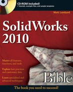
In this example, I created a sketch pattern of 4 × 4 rectangles and used the Fully Define Sketch tool to add dimensions. Then I copied and pasted the sketch and removed all the dimensions and relations. Figure 8.2 shows the Feature Statistic results.
It is safe to say that fully defined sketches are best practice, but it is not due to rebuild speed. Sketch relations are costly from a rebuild time point of view. Patterning sketch relations are even more costly. The rebuild time does not even come close to the time that it takes the Fully Define Sketch tool to create all the dimensions and relations in the first place. This combination of geometry, software, and hardware took about 30 seconds of CPU time to add the relations and dimensions.
It is best to pre-select the sketch entities that you want to pattern before using the Sketch Pattern tool. If you do not pre-select, then after the PropertyManager is open, you can only select entities to pattern one by one, because the window select is not available for this function.
Tip
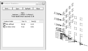
When creating a linear sketch pattern, be sure to select the Add Spacing Dimension check boxes. If these dimensions are not added, then editing the pattern becomes more difficult.
Unlike other PropertyManagers, the selected entities for the sketch pattern functions are found at the bottom of the PropertyManager instead of at the top. This is a little confusing. Sketch tool PropertyManagers that are new for the 2010 version, such as Convert Entities and Mirror, place the selection box at the top.
The Direction 1 panel works predictably by establishing the direction and spacing, and then the number. The Angle setting enables you to specify a direction that does not rely on anything outside of the sketch.
The Direction 2 panel works a little differently. You must first specify how many instances you want, and then the other information becomes available. The spacing is grayed out until you tell it you want more than one instance in Direction 2.
Mirroring in a sketch is a completely different matter from patterning in a sketch. It offers superior performance, and the interface is better developed. Mirrored entities in a sketch are an instrumental part of establishing design intent.
Two methods of mirroring items in a sketch are discussed here, along with a method to make entities work as if they have been mirrored when in fact they were manually drawn.
One feature of Mirror Entities may sometimes cause unexpected results. For example, in some situations, Mirror Entities will mirror a line or an arc and merge the new element with the old one across the centerline. This happens in situations where the mirror and the original form a single line or a single arc. SolidWorks may delete certain relations and dimensions in these situations.
When you activate this function, the centerline displays with hatch marks on the ends and remains active until you turn off or exit the sketch. Figure 8.5 shows the centerline with hatch marks.
Chapter 31 deals with 3D sketches in more detail, but I discuss the mirror functionality here to connect it with the rest of the mirroring and patterning topics. 3D sketches can contain planes and if you are sketching on a plane in a 3D sketch, you can mirror items on it. You cannot mirror general 3D sketch entities.
Sketch patterns are also unavailable in the 3D sketch, but you can use the Move, Rotate, and Copy sketch tools on planes in 3D sketches. Combining one questionable functionality (3D sketches) with another (sketch patterns) does not usually improve either one.
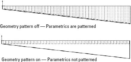
The SolidWorks Help file says that the Geometry Pattern option in feature patterns results in a faster pattern because it does not pattern the parametric relations. This claim is valid only when there is an end condition on the patterned feature such that the feature will actually pattern the end condition's parametric behavior. The part shown in Figure 8.6 falls into this category. The improved rebuild time goes from .30 to .11 seconds. Although a 60 percent reduction is significant, the most compelling argument for the use of the Geometry Pattern has nothing to do with rebuild time. It is to avoid the effect of patterning the end-condition parametrics.
In fact, the Geometry Pattern option's main intent is to pattern existing geometry without the parametric intelligence. The main mission of Geometry Pattern has nothing to do with rebuild speed.
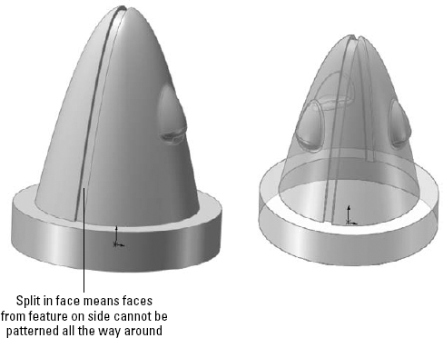
Under some conditions, Geometry Pattern will not work. One example is any time a patterned face merges with a face that cannot be patterned. Figure 8.7 shows two patterns, one that can use Geometry Pattern and one that cannot.
The pattern of the rectangular feature cannot use Geometry Pattern because the face that is merged is not merged in all pattern instances. The circular pattern can use Geometry Pattern because the flat face is merged in every pattern instance. The circular pattern also allows Geometry Pattern for the same reason.
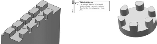
In some situations, SolidWorks error messages may send you in a loop. One message may tell you that the pattern cannot be created with the Geometry Pattern turned on, so you should try to turn it off. When you do that, you may get another message that says the pattern will not work, and that you should try to use the Geometry Pattern setting. In cases like this, you may try to use a different end condition, or change the selection of features patterned along with the feature, such as fillets. You may also try to pattern bodies or even faces rather than features.
I cover multi-bodies in depth in Chapter 26, but need to deal with the topic here briefly. Any discussion of patterning is not complete without a discussion of bodies because using bodies is an available option with all the pattern and mirror types.
SolidWorks parts can contain multiple solid or surface bodies. A solid body is a solid that comprises a single contiguous volume. Surface bodies are different, but they can also be patterned and mirrored as bodies.
There are both advantages and disadvantages to mirroring and patterning bodies instead of features. The advantages can include the simplicity of selecting a single body for mirroring or patterning. In cases where the geometry to be patterned is complex or there is a large number of features, patterning bodies also can be much faster. However, in the example used earlier with patterning features in a 20-by-20 grid of holes, when done by patterning a single body of 1" × 1" × .5" with a .5" diameter hole, patterning bodies gives a rebuild time of about 60 seconds with or without Verification on Rebuild. The function combines the resulting bodies into a single body that takes most of the time. This says that for large patterns of simple features, patterning bodies is not an efficient technique. Although I do not have an experiment in this chapter to prove it, it seems intuitive that creating a pattern of a smaller number of complex bodies using a large number of features in the patterned body would show a performance improvement over patterning the features.
Another disadvantage of patterning or mirroring bodies is that it does not allow you to be selective. You cannot mirror the body minus a couple of features without doing some shuffling of feature order in the FeatureManager. Another disadvantage is that if the base of the part has already been mirrored by a symmetrical sketch technique, then body mirroring is not going to help you mirror the subsequent features. In addition, the Merge Bodies option within the mirror feature does not work, as you would want it to. It merges only those bodies that are part of the mirror to bodies that are part of the mirror. Pattern Bodies does not even have an option to merge bodies. Both of these functions are often going to require an additional combine feature (for solid bodies) or knit (for surface bodies) to put the final results together.
Some of these details may seem obscure when you're reading about them, but when you begin to work patterning bodies and begin trying to merge them into a single body, read over this section again. The inconsistency between the Merge option existing in Mirror but not in Pattern is unexplainable, and a possible opportunity for an enhancement request.
Cross-Reference
Bodies are discussed in more detail in Chapter 26. Surface modeling is covered in Chapter 27.
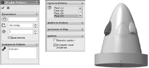
Most of the pattern types have an option for Pattern Faces. This option has a few restrictions, the main limitation being that all instances of the pattern must be created within the boundaries of the same face as the original. Figure 8.8 shows an example of the Pattern Faces option working with a Circular Pattern feature. To get around this limitation, you can knit and pattern the surface body, as shown in Figure 8.9.
Patterning faces is another way of patterning geometry within SolidWorks without patterning the feature intelligence that was built into the original. It is also a way to make patterns on imported parts from existing geometry. Chapter 30 comes back to this topic briefly in the discussion on imported geometry and direct edit techniques.
Cross-Reference
Working with surface bodies is covered in Chapter 27.
You may hear people argue that you cannot pattern fillets. This is only partially true. It is true that fillets as individual features cannot be patterned. For example, if you have a symmetrical box and a fillet on one edge and want to pattern only the fillet to other edges, this does not work. However, when fillets are patterned with their parent geometry, they are a perfectly acceptable candidate for patterning. This is also true for the more complex fillet types, such as variable radius and full radius fillets. You may need to use the Geometry Pattern option, and you may need to select all the fillets affecting a feature, but it certainly does work.
Up to now, I have discussed patterns in general; differentiated sketch patterns from feature patterns, face patterns, and body patterns; and looked at some other factors that affect patterning and mirroring. I will now discuss each individual type of pattern to give you an idea of what options are available.
Single direction or two directions. Directions can be established by edge, sketch entity, axis, or linear dimension. If two directions are used, the directions do not need to be perpendicular to one another.
Spacing. The spacing represents the center-to-center distance between pattern instances, and can be driven by an equation.
Number of Instances. This number represents the total number of features in a pattern, which includes the original seed feature. It can also be driven by an equation. Equations are covered in detail in Chapter 9.
Direction 2. The second direction works just like the first, with the one exception of the Pattern Seed Only option. Figure 8.10 shows the difference between a default two-direction pattern and one using the Pattern Seed Only option.
Instances to Skip. This option enables you to select instances that you would like to leave out of the final pattern. The pink dots are the instances that remain, and the red dots are the ones that have been removed. Figure 8.11 shows the interface for skipping instances. You may have difficulty distinguishing the red and pink colors on the screen.
Propagate visual properties. This option patterns the color, texture, or cosmetic thread display, along with the feature to which it is attached.
Vary Sketch. This option in patterns is often overlooked and not widely used or understood. While it may have a niche application, it is a powerful option that can save you a lot of time if you ever need to use it.
Vary Sketch allows the sketch of the patterned feature to maintain its parametric relations in each instance of the pattern. It is analogous to Geometry Pattern. Where Geometry Pattern disables the parametric end condition for a feature, Vary Sketch enables the parametric sketch relations for a pattern.
To activate the Vary Sketch option, the Linear Pattern must use a linear dimension for its Pattern Direction. The dimension must measure in the direction of the pattern, and adding the spacing for the pattern to the direction dimension must result in a valid feature.
The sketch relations must hold for the entire length of the pattern. Figure 8.12 shows the sketch relations and the resulting pattern. The preview function for this feature does not work.


On the CD-ROM
To better understand how this feature works, open the sample file from the CD-ROM called Chapter 8 Vary Sketch.sldprt, and edit Sketch2.
Edit the .40-inch dimension. Double-click it and use the scroll arrow to increase the dimension; watch the effect on the sketch. If a sketch reacts to changes properly, then it cannot be used with the Vary Sketch option. In this case, the .40-inch dimension is used as the direction. The direction dimension has to be able to drive the sketch in the same way that this one does. These dimensions cannot pass through the Zero value and cannot flip directions or move into negative values.
To make the sketch react this way to changes in the dimension, the slot was created using the bi-directional offset that was demonstrated in an earlier chapter, which means that the whole operation is being driven by the construction lines and arcs at the centerline of the slot. Sketch points along the model edges are kept at a certain distance from the ends of the slots using the .50-inch dimensions. The arcs are controlled by an Equal Radius relation and a single .58-inch radius dimension. The straight lines at the ends of the slots are controlled by an Equal Length relation.
This type of dimensioning and relation creation is really what parametric design is all about. The Vary Sketch option takes what is otherwise a static linear pattern and makes it react parametrically in a way that would otherwise require a lot of setup to create individual features. If you model everything with the level of care that you need to put into a Vary Sketch pattern feature sketch, then your models will react very well to change.
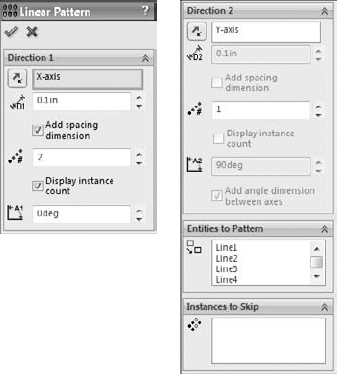
Equal Spacing takes the total angle and evenly divides the number of instances into that angle. The name equal spacing is a bit misleading because all Circular Patterns create equal spacing between the instances, but somehow everyone knows what they mean.
Without using the Equal Spacing option, the Angle setting represents the angular spacing between instances.
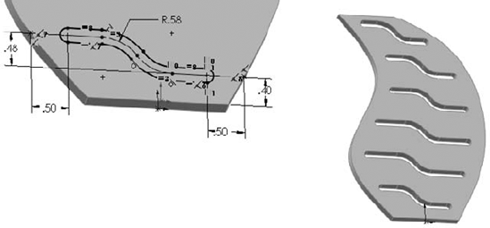
The Vary Sketch option is available in Circular Pattern as well. The principles for setup are the same, but you must select an angular dimension for the direction. The part shown in Figure 8.13 was created using this technique.

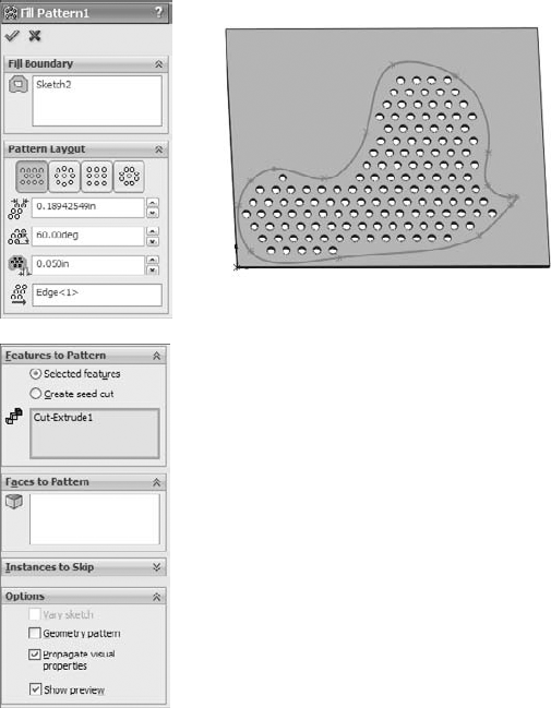
For an entire sketch to be used as a curve, the sketch must not have any sharp corners — all the entities must be tangent. This could mean using sketch fillets or a fit spline. The example shown in Figure 8.14 was created using sketch fillets. This pattern uses the Equal Spacing option, which spaces the number of instances evenly around the curve. It also uses the Offset Curve option, which maintains the patterned feature's relationship to the curve throughout the pattern, as if an offset of the curve goes through the centroids of each patterned instance. The Align to Seed option is also used, which keeps all the pattern instances aligned in the same direction.
Figure 8.15 shows the same part using the Transform Curve positioning option and Tangent to Curve alignment option.
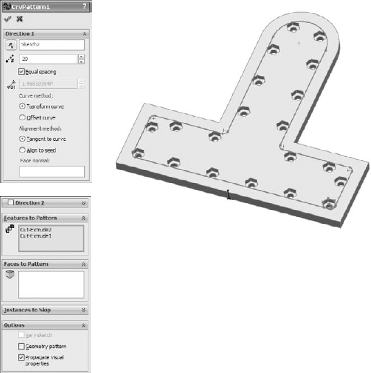
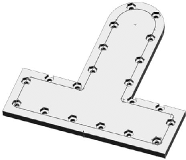
Instead of an offset of the curve going through the centroids of each patterned feature instance, in the Transform Curve, the entire curve is moved rather than offset. On this particular part, this causes a messy pattern. The Tangent to Curve option gives every patterned instance the same orientation relative to the curve as the original.
The Face Normal option is used for a 3D pattern, as shown in Figure 8.16. Although this functionality seems a little obscure, it is useful if you need a 3D curve-driven pattern on a complex surface. If you are curious about this example, it is on the CD-ROM with the filename Reference 3d Curve Driven.sldprt.
Using a Direction 2 for a Curve Driven Pattern creates a result similar to that in Figure 8.17. This is another situation that, although rare, is good to know about.
The rest of the Curve Driven Pattern works like the other pattern features that have already been demonstrated.


The Centroid option in the Reference Point section is fine for symmetrical and other easily definable shapes such as circles and rectangles, where you can find the centroid just by looking at it, but on more complex shapes, you may want to use the Selected Point option. The Selected Point option is shown in Figure 8.19.


The X, Y Origin for the table is determined by a Coordinate System reference geometry feature. The XY plane of the Coordinate System is the plane to which the XY data in the table refers.
You can access the Coordinate System command by choosing Insert
The fact that this feature is still in a floating dialog box points to its relatively low usage and priority on the SolidWorks upgrade schedule. The interface for the feature is rather crude in comparison to some of the more high-usage features. This interface is shown in Figure 8.20.

Cosmetic Patterns are not patterns in the same sense as all the other pattern types in SolidWorks. Cosmetic Patterns do not actually create any geometry, just the appearance of geometry. They are applied using RealView functionality, which may or may not be available to you depending on your hardware, in particular your video card.
Note
More information is available on RealView capable video cards from the SolidWorks corporate Web site, at www.solidworks.com/pages/services/VideoCardTesting.html?lsrc=quick_links.
Cosmetic Patterns are appropriate if your manufacturing method does not require actual geometry. For example, rapid prototyping requires explicit geometry in order to build a part, but a perforated sheet metal panel or a knurled cylindrical handle may require only a note on a drawing for the shop to set up a manufacturing process to create the geometry.
To apply a Cosmetic Pattern to a face, feature, body, or entire part, click the RealView tab from the Task Pane, and choose Appearances
Cross-Reference
You can find more details about RealView appearances in Chapter 5.

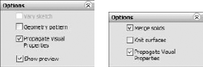
Earlier in this chapter, I discussed patterning bodies. I mentioned that the patterning and mirroring tools in SolidWorks do not have adequate functionality when it comes to body management. Neither tool allows the patterned or mirrored bodies to be merged with the main body if the main body is not being patterned or mirrored. Figure 8.23 shows the Options panels for both the Linear Pattern (on the left) and the Mirror (on the right) features. Here you can see that the pattern function has no provision whatsoever for merging bodies. The Mirror appears to have the functionality, but it applies only to bodies that are used or created by the Mirror feature.
In future versions of SolidWorks, we hope these features will be outfitted with more complete merge and feature scope functionality, such as Extrude features.
Best Practice
Mirroring bodies is the fastest and simplest method when a part has complete symmetry. However, this may not be an option if the part is not completely symmetrical. In addition, the decision to mirror must often be made when you are creating the first feature. If the first feature is modeled as a sketch that is built symmetrically around the Origin, then you may need to cut the part in half to mirror it. This is an adequate modeling technique, although it is not as clean as it could be.
Features can be mirrored across planes or flat faces used as the plane of symmetry. If you are mirroring many features, then it is best to mirror them all with a single mirror feature rather than to make several mirror features. You may have to do this by moving the mirror feature down the tree as you add new features. Depending on your part and what you are trying to accomplish, it may be better to mirror bodies than features, but you should not go too far out of your way or model in a contrived manner to make this happen.
Often when modeling, you are required to have a left- and a right-handed part. For this, you need to use a method other than body or feature mirroring. The Mirror Part command creates a brand new part by mirroring an existing part. The new part does not inherit all the features of the original, and so any changes must be created in the original part. If you want different versions of the two parts, you need to use Configurations, which have not been covered yet in this book.
Cross-Reference
Configurations are covered in detail in Chapter 10.
You can use the Mirror Part command by pre-selecting a plane or planar face. You should be careful when choosing the plane because the new part will have a relationship to the part Origin, based on the plane on which it was mirrored.
The Mirror Part command is found in the Insert menu. When mirroring a part, you can bring several entity types from the original file to the mirrored part. These include axes, planes, cosmetic threads, and surface bodies. Sketches and features are two commonly requested items to be brought forward by the Mirror Part command, but this is not possible in the current version of the software.
Mirror Part invokes the Insert Part feature, which is covered in more detail in Chapters 26 and 28, on multi-bodies and Master Model techniques, respectively.
One of the options available when you make a mirrored part is to break the link to the original part. This option brings forward all the sketches and features of the original part, and then adds a Move/Copy Body feature at the end of the tree that simply mirrors the body.
Note
Under normal circumstances, you cannot get the Move/Copy Body feature to mirror a body. SolidWorks has applied some magic pixie dust behind the scene to make this happen.
Follow these steps to get practice with creating circular pattern features:
Draw a square block on the Top plane centered on the Origin, 4 inches on each side, .5-inch thick extruded Mid Plane with .5-inch chamfers on the four corners.
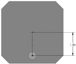
Pre-select the top face of the block and start the Hole Wizard. Select a counterbored hole for a 10–32 socket head cap screw, and place it as shown in Figure 8.24.
Create an axis using the Front and Right planes. Choose Insert

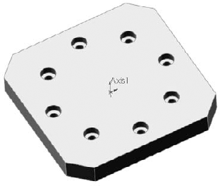
Click the Circular Pattern tool on the Features toolbar. Select the new Axis in the top Pattern Axis selection box in the Circular Pattern PropertyManager. Select the Equal Spacing option and make sure that the angle is set to 360°. Set the number of instances to 8.
In the Features to Pattern panel, select the counterbored hole. Make sure that Geometry Pattern is turned off.
Click OK to finish the part, as shown in Figure 8.25.
Follow these steps to get some practice with creating mirror features:
Open the file from the CD-ROM called
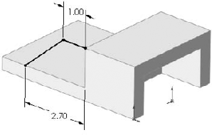
Chapter8 Tutorial2.sldprt.Open a sketch on the side of the part, as shown in Figure 8.26. The straight line on top is 1.00 inch long, and the angled line ends 2.70 inches from the edge, as shown.
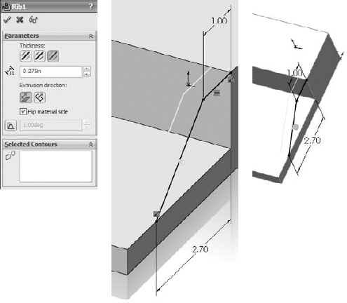
Click the Rib tool on the Features toolbar or select it from the menu at Insert
FeaturesRib. Set the material arrow to go down toward the block, and the thickness setting to go to the inside by .375 inches. The PropertyManager and the preview should look like Figure 8.27.Create a linear pattern using the rib, making the pattern reach 2 inches into the part.
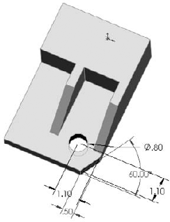
Create a chamfer on the same side of the part as the original rib, as shown in Figure 8.28. The chamfer is an Angle-Distance using 60° and .5 inches.
Create a round hole, sized and positioned as shown.
Mirror the hole and the chamfer about the Right plane. The parametrics of the chamfer will have difficulty patterning, and so you need to use the Geometry Pattern option. The finished part is shown in Figure 8.29.

Open the file from the CD-ROM for Chapter 8 called Chapter 8 –
tutorial – cosmetic pattern.sldprt.Click the Appearances tab in the Task Pane. These steps will work whether or not you have RealView actually selected.
Expand the Appearances heading, then the Metal heading, then Steel, and then drag the Sandblasted Steel icon from the lower panel onto the part. When the popup menu appears, select the Part icon, to apply the appearance to the entire part. Figure 8.30 shows the Task Pane and the popup menu.
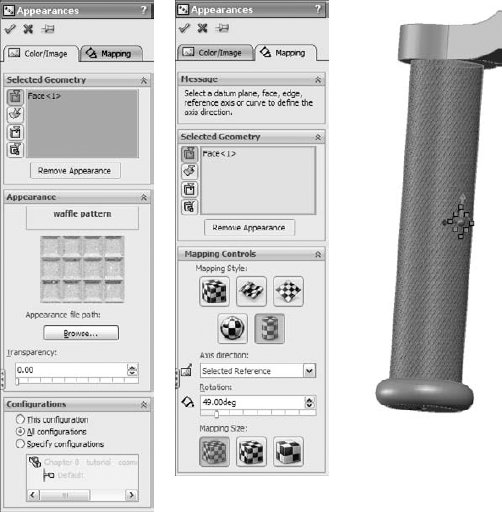
Expand the Miscellaneous listing (under Appearances) and the Pattern heading. Drag the Waffle Pattern onto the large cylindrical face of the part, and then Alt-click the Face icon in the popup toolbar. Using the Alt key while dragging or to select face, feature, body, or part automatically activates the PropertyManager to edit the appearance. Figure 8.31 shows the Appearances PropertyManager.
In the Mapping tab of the Appearances PropertyManager, select the cylindrical mapping under the Mapping Style section of the Mapping Controls panel.
Change the Rotation to 45 degrees, and choose the smallest Mapping Size.

Feature patterns and mirrors are powerful tools, but you need to have some discipline to benefit from their usefulness. Patterns in particular are extremely flexible, with many types of functions and options available. You should avoid sketch patterns if possible, not only because of performance considerations, but also because complex sketches (sketches with a lot of entities and relations) tend to fail more often than simple sketches.