
Parametric sketch relations are not the only way to drive dimensions with intelligence. You can also use equations, link values, and global variables. Equations help you create simple or complex mathematical relations between dimensions. Link values are essentially a quick way of making two dimensions equal. Global variables can be used in equations like other dimension names. These three techniques are all very similar and related to one another in the interface, but are used in different ways in different situations.
Equations can cause problems if used incorrectly, and have functionality that may appear incorrect at times, but if you are familiar with how the tools work, you can avoid the common pitfalls and get maximum benefit by adding intelligence to your designs.
Using the Equations interface, you can turn off equations temporarily by deselecting the Active check box in front of the equation. Equations can also be deactivated by a design table. I will discuss design tables in more detail in Chapter 10, which discusses configurations.
Best Practice
Although I do not cover configurations until Chapter 10, I will mention part of the relationship between equations and configurations here. Equations and configurations (particularly those that are driven by a design table) should probably not be mixed. This is not because they do not work together, but more for the sake of organization. When controlling dimensions, it can become confusing if the changes are being driven from multiple sources. In addition, there is no reason not to bring your equations into Excel rather than using the comparatively limited equation functionality offered by SolidWorks. Of course, every user will have his or her own reasons for working one way or another, and this is really just a question of personal preference.
Equations are easy to create and useful for many purposes. A common situation where you would use an equation is to space a pattern of holes evenly along an edge, including the gap on both ends, where the gap at the ends is half of the regular spacing. Before you write an equation, you need to take care of a few organizational details.
It is not necessary to name every entity in every SolidWorks document, but you should get in the habit of naming important features, sketches, and even dimensions. Dimensions become particularly important when you use them in equations, configurations, and design tables. Under most circumstances, you do not use or even see dimension names, but with equations, you do.
Named dimensions make a huge difference when you want to recognize the function of an equation by simply reading it. A most obvious example would be the difference between D3@Sketch6 and Length@WindowExtrusionSketch. The first name means nothing, but the second one is descriptive if you are familiar with the part.
To name a dimension, click the dimension and go to the PropertyManager. In the Primary Value panel shown in Figure 9.2, type the new name for the dimension in the Name text box. You cannot use the symbol @ in dimension names because it is used as a delimiter between the name of the dimension and the feature or sketch to which it applies. Also, be aware that even though the software allows you to change the name of the sketch or feature in the Dimension PropertyManager, it will not accept this change.

Best Practice
You should keep dimension names as short as possible while still making them unique and descriptive. This is because space in the interface is often limited, and when combined with sketch or feature names (and even part names when used in an assembly), the names can become difficult to display in a readable fashion.
Tip
You can show dimension names as a part of the dimension itself; choose View
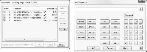
When creating an equation in SolidWorks, it is often a good idea to write it out on paper first. Examine the part shown in Figure 9.4, where the relevant dimensions have been named and displayed. The number of holes — called Instances here — is the driving variable. From that number, the spacing of the holes is calculated over the length of the part. There is also a gap on each end of the pattern of holes. This gap (measured between the center of the last hole and the end of the part) always needs to be half of the spacing between the holes. The sigma symbols to the left of the dimensions indicate that an equation is driving it. Dimensions driven by equations cannot be directly edited.

In this case, a more sophisticated equation has not been implemented to account for the diameter of the holes possibly interfering with one another when there are a large number of holes. In other words, because there are two values that need to be calculated (the spacing and the gap), you need to create two equations. Because the gap dimension is always half of the spacing, the spacing needs to be calculated first, as follows:
Spacing = Length / ((Instances-1)+1)
The Instances −1 term stands for the number of spacings. If you have two holes, then there is only one spacing. The +1 term stands for the two half-spacings for the two ends. The second equation is simpler and looks like this:
Gap = Spacing / 2
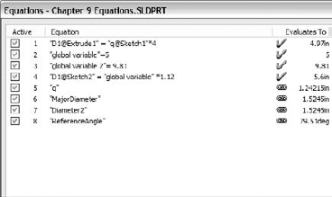
The order of the equations is important. SolidWorks solves the equations in the order in which they are listed in the Equations dialog box. Because the gap is dependent on the spacing, the spacing must be calculated before the gap. If it is done the other way around, you can get into a situation where it takes two rebuilds to finalize a set of equations, or even a situation where in every rebuild all the numbers change. This is called a circular relation, and is a common error in order or history dependent functions, not just in SolidWorks, but in many CAD applications. Figure 9.5 shows the resulting set of equations.

Before beginning to build the equation, you should first display the dimensions that you need to use to create the equation. You can add dimensions to the equation by clicking them from the graphics window. To do this, right-click the Annotations folder at the top of the FeatureManager, and select Show Feature Dimensions. You should also select the Display Annotations option if it is not already selected. When you have done this, all the dimensions that you need to create every feature are displayed. Also, be sure to turn on the Show Dimension Names option by choosing Tools
Tip
For models that have more than a few features, showing all the dimensions in the entire model may overload the screen with information. In this case, you can double-click a feature from the FeatureManager to show all the dimensions on that feature.
To build the equation, first click the Equation button on the Tools toolbar to open the Equations dialog box. Then click the Add button to display the Add Equation dialog box. To add dimensions to the equation section, just select the dimension. You can use the keypad on the dialog box or on your keyboard to add operators and syntax. All standard rules of syntax apply for the order of operations, use of parentheses, and driving versus driven sides of the equation.
Notice the comment to the right of the first equation in Figure 9.5. Comments can be very useful for annotating equations for yourself or others. Two important reasons to annotate are to remember the significance of variables or dimensions and to add special notes about the logic of the equation.
You can make comments for equations by using a single quote after the end of the equation, or by clicking the Comment button in the Add Equation dialog box. In the following example, the comment, "This must be solved first," is applied to the equation using the single quote before the comment.
"Spacing@LPattern1" = "Length@Sketch1" / ("Instances@LPattern1")
   'This must be solved first
To expand on the earlier discussion about projected changes to the Equation interface, several standard selection functionalities do not work in the Edit Equation dialog box. These include triple-clicking to select all (although double-clicking works to select a single word) and pressing Ctrl+A to select all.
Tip
You can make general comments for the model in the Design Journal, a Microsoft Word document that is embedded into the SolidWorks file. The Design Journal is found in the Design Binder folder near the top of the FeatureManager.
On the CD-ROM
You can find the part used in this section on the CD-ROM with the filename Chapter 9 Equations.sldprt.
Sometimes it is more convenient to use a driven (reference) dimension in an equation. This is particularly true when using geometry is the best way to calculate a number. For example, if you are manufacturing a helical auger in 90-degree sections from flat steel stock, then you need to design the auger in 3D, but begin to manufacture it in 2D.
What is the shape of the auger when flat? The best way to figure this out (aside from lofted bends, which are discussed in Chapter 29) is to use a little high school geometry, a construction sketch, and some simple equations.
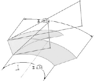
Figure 9.6 shows a 90-degree section of an auger blade. The outside diameter is 12 inches, and the blade width is 3 inches. The overall height is 4 inches. In this case, the auger is represented as a surface because the thickness is ignored. Surface features can be useful in situations like this (used as construction geometry) and are discussed in Chapter 27.

On the CD-ROM
You can find the part for Figure 9.6 on the CD-ROM with the filename Chapter 9 Auger.sldprt.
With this information, you can calculate the lengths of the 3D edges using a sketch and a simple equation. In Figure 9.7, the hypotenuses of the triangles represent the helical edges of the inside and outside of the auger. By making the triangles the same height as the auger section, and by making the horizontal side of the triangle the same length as a quarter of the inside or outside diameter by using simple equations, the geometry and sketch relations automatically calculate the flat lengths of the inside and outside edges of the auger (length of triangle side = diameter of circle × pi / 4). In this way, the triangle is used to simplify the calculation, and give it a visual result.

From this point, you can calculate the flat pattern again, using SolidWorks' sketch-solving capabilities as the calculator. Think of the auger as being the cardboard tube inside a roll of paper towels. If you examine one of these tubes closely, you see that it is simply a straight and flat strip of cardboard that has been wound around a cylinder. What was the flat, straight edge of the original board is wound into a helix. This method simply reverses that process.
This example requires the little-used arc-length dimension to drive the size of the arc. The hypotenuse dimensions are shown by driven or reference dimensions, and these are used to drive the arc-length dimensions, as shown in Figure 9.8. Remember that you can create arc length dimensions by using the Smart Dimension tool to click both endpoints of the arc and then the arc itself.
The reasoning behind this example may be a little difficult to grasp, but the equations and the sketches are certainly simple.
Warning
Using reference dimensions on the driving (independent or right) side of the equation can, and in some situations, require more than one rebuild to arrive at a stable value (meaning a value that does not change with the next rebuild). SolidWorks issues a warning when it sees that you are using a reference dimension in an equation, but it does allow it.
Some functions that are permitted in SolidWorks equations are often viewed as parlor tricks, but they actually do have some practical applications. The two functions that fall into this category are IIF and SWITCH. If you are familiar with any programming language, you may already be familiar with these two functions.
In words, this is how an IIF statement is used:
If some relationship is fulfilled, then the IIF function returns a value. If the relationship is not fulfilled, then it returns a different value.
A more technical description is
IIF(expression, value if true, value if false)
In practice, you could use it like this:
IIF(x>5, x-1, x+1)
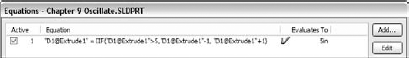
which reads, "if x is greater than 5, then subtract 1 from x; if not, then add 1 to x." One of the reasons why this is considered a parlor trick is that this function causes the value of x to oscillate between two numbers (depending on the number that it starts with) with each rebuild. It may be difficult to imagine an application where this sort of behavior would be desirable, but when you combine it with a macro that simply rebuilds a model a number of times, you can use it to create a certain animation effect.
On the CD-ROM
A simple example of the IIF function can be found on the CD-ROM with the filename Chapter 9 Oscillate.sldprt. The equation is shown in Figure 9.9.
Tip
You can find some great examples of this function at www.mikejwilson.com, along with many other extremely creative examples of SolidWorks modeling. The model on this site called Ship in a Bottle.sldprt also includes a macro that will rebuild the model a certain number of times, which is useful for animations that are created in this way.
The SWITCH function enables you to have a list of relationships with associated values. The value of the first relationship in the list that is satisfied is returned by the SWITCH function. For example,
switch (x>2, 1.5, x>1, .5 x<1, 2.5)
reads as follows: "if x is greater than 2, then the answer is 1.5; if x is not greater than 2 but greater than 1, then the answer is .5; if x is less than 1, then the answer is 2.5."
As you can see, this function does not cover all situations, but it does create a condition where the value cycles through three different numbers in a specific order. Is this useful? Possibly. Again, the main application for this function would be a simple animation for changing the size or shape of SolidWorks components that cannot be changed in other more conventional ways.
Link values are simply a way to link several dimensions together, making them equal. A link value is not exactly like an equation that sets the dimensions equal, because it does not depend on order like an equation does. All dimensions are set to the same value simultaneously.
Link values are available by right-clicking on a dimension. You can also get to link values by clicking the down arrow on the right side of the Modify dialog box. Unfortunately, they are not available from the RMB menu when the dimension tool is active. To apply a link value to a new dimension, you must place the dimension, exit the dimension tool, right-click the dimension, and select Link Value.
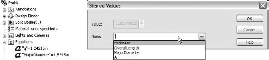
Link values are listed under the Equations folder in the FeatureManager. Figure 9.10 shows the link values in a listed part, and the drop-down list from which you can select them or type them. Notice again that the Link Values feature also operates from a dialog box instead of the PropertyManager.
Note
Another way to access link values is through the Modify dialog box. If you click the down arrow at the right end of the dimension value box, you can select between Link Values and Equations. In fact, if you press the Down Arrow key on the keyboard, the Equation interface becomes available. There is no similar trick to get Link Values to appear.
You must type in the first link value that is assigned in a part. After you add the first one, you can link other dimensions to this link value by using the drop-down arrow shown in Figure 9.10. You cannot edit link values, meaning you cannot change a dimension from linking to a value called "height" to a value called "length." In order to change the value to which a dimension is linked, you must first unlink the value and then relink it. The Unlink function is available from the RMB menu in the same way that you assign link values. Dimensions that have a link value have the small chain symbol displayed to the left of the dimension.
To link several dimensions to the same value at the same time, you can Ctrl+select multiple dimensions and then right-click one of them and select Link Value. It will link all the dimensions selected at once. (Thanks to Brian McElyea for this suggestion!)
Tip
One link value name has a special significance. If you use the name thickness, then a Link To Thickness option appears in all extrude dialog boxes. This is intended to reflect sheet metal functionality, but it is useful for models of various manufacturing techniques.
To take this one step further, you can save a part template with a thickness link value; all your new parts will also have this functionality right from the start. To save the template with a link value, you must create at least one dimension to assign the link value, and then delete the geometry (and the dimension); however, the link value will remain.
Link values of different types are not necessarily interchangeable. You cannot use angular dimension link values on radius, diameter, or linear dimensions. You can use linear and diameter link values interchangeably, but not angle link values.
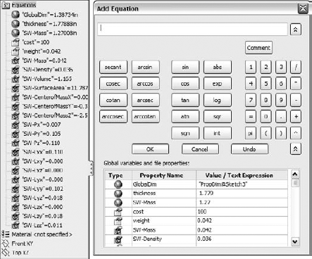
Global variables are assigned in the Equations dialog box as simply the variable name equaling the value. Figure 9.11 shows a list of equations, link values, and global variables. When you type in a variable name, you do not need to add the quotation marks; they are added automatically.
Despite the word variable in the name global variable, the values are not variable. They are fixed, and only changeable through the Equations dialog box. The only place you can use global variables is in equations. You cannot directly enter them into dialog boxes for dimension values, or use them like Link Values.
You can use custom and file properties to drive equations. If you right-click your Equations folder and select Show Properties, you see that the default file properties already exist in the list:
| Global Variable |
| Custom Property |
| Default File Property |
In the equation editor shown on the right in Figure 9.12, you can expand the list of global, custom, and default properties for easy selection and placement into equations. Any custom properties you add that are of the type "number" are automatically added to this list and can be used in equations. Notice that the custom property "cost" is a property saved in my template and gets picked up for use here.
Expressions, unlike all the previous variables, values, and equations, can be entered directly into dimension dialog boxes in the Modify dialog box and PropertyManager value boxes. The expressions have to be composed of numbers and mathematical operators. An expression such as
2.375+(4.8/3) −1.1
is perfectly acceptable, as is
1+1/2
or
1 1/2
In the second case in this example, the plus symbol is understood.
Other types of operations are also available, such as ones for changing units in a dimension box. For example, if you are editing a part in inches, and enter 40mm, then SolidWorks does the conversion for you. You can even mix units in a single expression such as 4.875+3.5mm, where the inch part is assumed as the document units.
SolidWorks does not remember the expression itself, only the final value. Expressions can be entered into any place where you enter dimensions for SolidWorks features.
Follow these steps to get some practice with using equations:
Start from the part on the CD-ROM with the filename
Chapter9 Tutorial Start.sldprt.Show the dimension names. Choose View

Double-click the Circular Pattern feature to display the angle and number of instances of the feet and related features. You may have to move the angle dimension to see the pattern instance number.
Click the instance number. Change the name of the dimension to # (pound or number sign) in the Dimension PropertyManager. Make sure that Instant3D is unselected when doing this.
Double-click the first feature, which is the revolve, and rename the 3.60-inch dimension CapRad, again by selecting it and using the PropertyManager.
Write an equation that drives the number of legs by CapRad/7.
Open the Equations dialog box by choosing Tools
Click Add to add an equation.
Double-click the Circular Pattern and click the # dimension. Make sure that the name of the dimension is listed in the equation box, and type an equal sign.
Double-click the Revolve feature and select the CapRad dimension; then type the characters /1.5.
Add a comment to the equation to reflect which dimension is driving which dimension.
Click Rebuild, press Ctrl+B or Ctrl+Q to rebuild the model, and observe whether any update takes place.
Rename the 6.00-inch dimension for the height of the revolved feature to DomeHt.
Create a second equation that drives the DomeHt dimension at the current ratio of the height to the radius.
Create a global variable called Ratio = 6/3.6 (1.66667) in the Equations dialog box.
Create the equation. The equation will take the form of DomeHt = (Ratio) × CapRad. You can use the drop-down list under the calculator pad to select the Ratio variable from the list.
Use a link value to make the radii of Fillet1 and Fillet2 the same.
Double-click the revolve feature. Change the .CapRad dimension to 5 and rebuild. You should observe 3 feet. Change it again to 6 and you should see 4 feet.
Give the part a new name, including your initials or the date, and save and close it.
SolidWorks equations and related dimension-management tools are powerful, but often leave you wishing for a little more flexibility and control. The interface is not up to date with the rest of the SolidWorks interface, and so I would look to see an updated equation interface soon that integrates dimension input, link values, and global variables.
If you want to encourage SolidWorks to revise certain features, then you can go to the SolidWorks Web site and submit an enhancement request. They do look at customer input when developing or updating functionality.