
IN THIS CHAPTER
Identifying elements of the SolidWorks interface
Making the interface work for you
Tutorial: Getting to know the interface
The good news is that the SolidWorks interface is very flexible, and if you're a Windows veteran, most of it is perfectly intuitive. The bad news is that there's a lot of it to know. This chapter serves as a reference, and to help you decide how you want to use different portions of the interface. In this chapter, you learn how to effectively navigate and manipulate the interface, and you learn how to customize it both to suit your personal style and to help you work faster. This customization includes adding and removing toolbar buttons, displaying descriptions on toolbars, accessing dynamic help options, using standard and custom hotkeys, and making your interface customization portable to other computers.
Many aspects of the SolidWorks interface are controlled by settings, which are covered in detail in Appendix B. Each interface element that is identified in Figure 2.1 is explained in greater detail in its own section of this chapter.
Once you have mastered the various interface elements and customized your SolidWorks installation, working with the software becomes much more efficient and satisfying.

When communicating with other users and tech support, it is important to use names for the various interface components that other people understand. This chapter is about learning the terminology and finding the tools that you need.
The SolidWorks GUI (Graphical User Interface) is highly dependent on toolbar icons. While some icons are self-explanatory, others require some explanation. In this chapter, we discuss the Standard toolbar, button by button, in order to identify each of the available tools. Other toolbars have more specific functions and are explained in detail in their respective chapters.
The Standard toolbar has many of the basic tools that are familiar to most Windows users. It is used for basic functions such as creating and saving documents, changing colors, and undoing and redoing actions. Although there may be some commands that new users are not familiar with, this section serves as a reference for all user levels; the more advanced commands are covered in their respective sections.
The commands are shown in the order in which they appear on the Tools
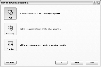
You can click the Advanced button in the lower-left corner of the dialog box to switch to the Advanced interface. The difference between the Novice and Advanced interfaces is that the Advanced interface allows you to use additional tabs and custom templates. You can create additional tabs by using Windows Explorer to add folders to the folder that is indicated in Tools
Note
Templates are discussed in more detail in Chapter 3.
Figure 2.3 shows the Advanced interface of the New SolidWorks Document dialog box.

Figure 2.4 shows the Open dialog box.
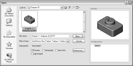
The Preview option enables you to view document thumbnails in the Preview box that is located in the upper-right area of the Open dialog box.
When you use the Advanced option with an assembly document, it brings up the Configure Document dialog box, shown in Figure 2.5, which enables you to:
Open the currently selected configuration.
Create a new assembly configuration with a specified name that shows all referenced models.
Create a new assembly configuration with a specified name that suppresses all parts in order to display only the assembly structure. (Suppressing all of the parts makes the assembly load instantly.).
Load the assembly using a specified part configuration name. For example, if you specify "Simplified," the assembly opens all parts in their "Simplified" configuration, if it exists.
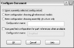
Figure 2.5. The Configure Document dialog box, which appears when you use the Advanced option in the Open dialog box
You can open the following types of documents from the Open dialog box:
Note
The file types in the list are not alphabetized in the SolidWorks window, which makes it difficult to browse for file types. They are alphabetized here for ease of reference.
ACIS (*.sat): ACIS files typically come from AutoCAD or CADKEY 3D models.
Add-Ins (*.dll): If you have applications that run through a dynamic link library, or DLL, then you can start the DLL from the Open command.
Adobe Illustrator (*.ai): You can open Adobe Illustrator files in SolidWorks as either sketch entities or sketch text.
CADKEY (*.prt, *.ckd): CADKEY files.
Catia Graphics (*.cgr): These are simply graphics files, not fully translated geometry files.
DWG (*.dwg): DWG files can be either 2D or 3D. It is best to use the DWG format to transfer only 2D files. Use the ACIS format to transfer AutoCAD 3D files.
DXF (*.dxf): DXF files can be either 2D or 3D. It is best to use the DXF format to transfer only 2D files. Use the ACIS format to transfer AutoCAD 3D files.
IDF (*.emn, *.brd, *.bdf, *.idb): These file types are used to transfer circuit-board data into SolidWorks.
IGES (*.igs, *.iges): IGES files can contain many types of information, but not all companies interpret it in the same way. SolidWorks works best with trimmed-surface IGES data. IGS data is sometimes used to transmit 2D data. SolidWorks does not typically do a good job of reading data in this format. You typically import 2D drawing data into SolidWorks as sketch entities. It is best to transfer 2D drawings as DWG or DXF files. Because of the variability of this data, it is not one of the preferred translation formats.
Inventor Part (*.ipt): SolidWorks can open Inventor files up to and including version 9.0; however, it interprets just the geometry, not a complete feature tree.
Library Features (*.lfp, *.sldlfp): Library features can include solid-feature geometry and sketches, and can also use configurations. These file formats are used for combinations of features that you use frequently, in order to save modeling time and to improve standardization.
Mesh (*.nxm, *.scn, *.3ds, *.obj, *.stl, *.wrl, *.ply, *.ply2): These are mesh formats that include STL and 3D Studio Max files, which can be used in ScanTo3D to create a surfaced-solid model.
Parasolid (*.x_t, *.x_b, *.xmx_txt, *.xmt_bin): There are two types of Parasolid files: binary and text. The binary files are typically about half the size of the text files, but you can read the text files with a text editor and extract certain information from the file header. SolidWorks is based on the Parasolid kernel, and so Parasolid is the preferred translation standard.
Point Cloud (*.xyz, *.txt, *.asc, *.vda, *.igs): Point cloud files are typically brought in either for reference or to use ScanTo3D in order to create surfaced-solid models.
Pro/Engineer Part (*.prt, *.xpr): SolidWorks can read versions 17 to 2001 of Pro/Engineer parts, as well as Wildfire versions 1 and 2.
Pro/Engineer Assembly (*.asm, *.xas): SolidWorks can read versions 17 to 2001 of Pro/Engineer assemblies, as well as Wildfire versions 1 and 2.
Solid Edge Part (*.par): SolidWorks reads the Parasolid data from Solid Edge files. To transfer Solid Edge drawings, DWG or DXF formats are preferred.
Solid Edge Assembly (*.asm): SolidWorks reads the Parasolid data from Solid Edge files. To transfer Solid Edge drawings, DWG or DXF formats are preferred.
SolidWorks Parts, Assemblies, and Drawings (*.sldprt, *.sldasm, *.slddrw): These are native SolidWorks-created documents or imported data saved as SolidWorks file type.
STEP AP 203/214 (*.step, *.stp): STEP stands for "STandard for the Exchange of Product" model data. AP stands for "application protocol," which signifies different types of STEP data. The number 203 indicates Configuration Controlled Design, and 214 indicates Core Data for Automotive Mechanical Design Processes. STEP is a reliable translation standard, although Parasolid is preferred.
STL (*.stl): STL is a tessellated or facetted format that is intended for the stereolithography process. You can import this format as a graphics body (with no selectable solid geometry), as a solid, or a surface. Keep in mind that because the data is tessellated, it cannot create smooth surfaces. Solid and surface imports severely degrade performance on any assembly into which they are placed. This is not a recommended format for import.
UGII (*.prt): Unigraphics 10 and higher, including NX parts, can be opened in SolidWorks. However, you should keep in mind that UG drawings and assemblies have the same extension, and do not open if there is no Parasolid data in the file.
VDAFS (*.vda): VDAFS is a German translation standard, which in my experience is at least as reliable as IGES.
VRML (*.wrl): VRML stands for "Virtual Reality Markup Language." Its usage for CAD applications is limited, having been primarily a game geometry format. Large file sizes and tessellated geometry typically prevent its extensive use for transferring CAD data, but the format has special graduated color options that enable you to create 3D colored plots for analysis applications. This is not a recommended format for import.
In addition to its native formats, SolidWorks can also save the following types of documents:
3D XML (*.3dxml): This is a new XML-based 3D display format that was created in 2005 by Microsoft and Dassault Systems for the integration of 3D images into documentation, Web sites, manuals, and other materials.
ACIS (*.sat): See the file-type description under the Open command list.
Adobe PDF (*.pdf): Prints the current document to a PDF file.
Catia Graphics (*.cgr): See the file-type description under the Open command list.
DWG (*.dwg): See the file-type description under the Open command list.
DXF (*.dxf): See the file-type description under the Open command list.
eDrawing (*.eprt, *.easm, *.edrw): eDrawing is a display-only format that you can publish either as a standalone file that requires a separate viewer, or with a viewer built into the actual file. It features a small file size (relative to full CAD documents) and allows the viewer to view in 3D, mark up, section, and move parts.
Form Tool (*.sldftp): This file type is specific to tools that form sheet metal. See Chapter 29 for more information.
IGES (*.igs): See the file-type description under the Open command list.
HCG (*.hcg): Catia Highly Compressed Graphics files. These files are display-only.
HOOPS HSF (*.hsf): HOOPS is a 3D graphics display format that is used by several 3D viewers.
JPEG (*.jpg): SolidWorks saves out the display as a JPEG image.
Library Feature Part (*.sldlfp): See the file-type description under the Open command list.
Microsoft XAML (*.xaml): Extensible Application Markup Language is a language for creating graphical interfaces for Windows Presentation Foundation, or WPF.
Parasolid (*.x_t): See the file-type description under the Open command list.
Parasolid Binary (*.x_b): See the file-type description under the Open command list.
Part (*.sldprt): SolidWorks part format.
Part Template (*.prtdot): SolidWorks part-template format. See Chapter 3 for more information on templates.
Pro/Engineer (*.prt, *.asm): This file format does not save a feature-based part, but only a "dumb" solid.
ScanTo3D (*.xyz, *.wrl, *.stl, *.3ds): See the file-type description under the Open command list, listed under the Mesh and Point Cloud headings.
Tiff (*.tif): SolidWorks can save out the print image as a TIFF file. This is particularly useful for exporting high-resolution drawings.
Universal 3D (*.u3d): This is a 3D display format that is used by Adobe.
VDAFS (*.vda): See the file-type description under the Open command list.
VRML (*.wrl): See the file-type description under the Open command list.

If these conditions are met and you click this button, you either receive a message that says that none of the read-only files in memory have been changed, or if they have been changed, the Reload dialog box displays with the changed parts in the dialog box, prompting you to reload the parts with write access.
Again, depending on your setup, the automatically created drawing may behave differently. If you use a template that contains pre-defined views, the views are automatically populated. Whether the View Palette appears depends on the setting at Tools
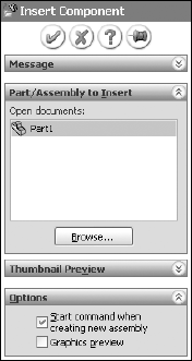
Another option that normally affects the function of this command is shown in Figure 2.8. The Make Assembly from Part/Assembly command opens a new assembly with the Insert Component PropertyManager dialog box open. The Start Command When Creating New Assembly option has no effect when you invoke a new assembly from the Make Assembly from Part/Assembly command. However, if you create a new assembly manually, this option controls whether or not the PropertyManager that selects models and places them in the assembly displays automatically.
Note
The Print Selection option is available only for drawings, and must be selected from the Print dialog box. It is assumed that when a model is printed, the selection is in the graphics window, which is printed for model documents.
This is different from 3D Printing, which is an option in the File menu that interfaces with 3D printer hardware that is connected to your computer.
The Delete command is also available in the right mouse button (RMB) menu and by using the Delete key on the keyboard.

There are two special uses of the Delete command. The first is when the selection is a surface or solid body. In this case, the Delete command results in a Delete Bodies feature being added to the FeatureManager, and the bodies being removed from the part. This is a history-based deletion, which means that if you roll back to before you used the Delete Bodies feature, the bodies are there again.
The second special use is when the selection is a closed-loop open edge of a surface body (such as a circular hole that is trimmed in the middle of a surface, and not at the edge); SolidWorks asks if you are trying to delete the feature or to delete the hole. This is similar to the Untrim feature.
Note
At times, a rebuild symbol may not disappear from a feature, forcing it to be rebuilt every time you make a change. In a component with a lot of features, this can create a serious performance problem.
Other times, the rebuild symbol may not be present, even when features need to be rebuilt. Whenever it looks like something is wrong with a feature, it is a good idea to use the Forced Rebuild command, which rebuilds everything whether or not the software thinks that it is necessary. There is no icon or menu selection for Forced Rebuild; it is only available through the Ctrl+Q hotkey.
Tip
When you are not sure at what level the color was applied (for example, face, feature, part, or component), you can use the Display pane and Display Callouts to identify colored entities.
Figures 2.10 to 2.25 show the most commonly used toolbars displaying their default icons. The SolidWorks interface uses over 500 icons.
The Annotation toolbar, shown in Figure 2.10, contains tools for notes, balloons, surface finish and weld symbols, Geometric Dimensioning and Tolerancing (GD&T), datums, hole callouts, cosmetic threads, center marks and centerlines, cross hatch, and dimensioning. By default, this toolbar appears on the drawings Command Manager, but it may also be added to parts or assemblies as needed. These tools are covered in detail in Chapter 21.
The Assembly toolbar, shown in Figure 2.11, contains tools that are used in assemblies only. These include visibility tools, mating and moving tools, exploded-view tools, and various analysis tools, among others. These tools are covered in depth in Chapters 12 to 16.
The Dimensions/Relations toolbar, shown in Figure 2.12, contains tools for creating all of the dimension types in SolidWorks, including ordinate dimensions. In addition to the Sketch toolbar, you can also find tools for working with sketch relations.
The Drawing toolbar, shown in Figure 2.13, contains tools for drawing view creation. You can also add buttons that do not display by default on the toolbar, including Empty View, Predefined View, and Update View. Update View is not a view type, but a command that updates all drawing views to the current state of the model. The tools on this toolbar are discussed thoroughly in Chapter 21.
By default, the Features toolbar, shown in Figure 2.14, contains the most commonly used solid features. Because there are a total of 47 feature commands, displaying them all on the toolbar is not practical. Everyone uses these features differently, and so you should customize your interface to match how you use the software. Surface features appear on a separate toolbar.
The Reference Geometry toolbar, shown in Figure 2.15, contains all of the available reference geometry tools. These include Plane, Axis, Coordinate System, Point, and Mate Reference.
The Selection Filter toolbar, shown in Figure 2.16, enables you to limit the selection to particular entity types. The filter works in conjunction with both manual selection and window selection.

The Sheet Metal toolbar, shown in Figure 2.17, contains all of the tools that are specific to sheet metal. Sheet Metal functionality is covered in detail in Chapters 29 and 30.
The Sketch toolbar is the most frequently used toolbar in SolidWorks. Figure 2.18 shows the default sketch entities on the Sketch toolbar, but there are many other entities that do not appear on it and that you may want to use. These entities include Ellipse, Centerpoint Ellipse, Spline on Surface, Split Entities, and many more.
The SolidWorks Office toolbar, shown in Figure 2.19, displays buttons for each of the add-ins in SolidWorks Office. However, not all of the available add-ins appear by default on the toolbar. The add-ins are:
Photoworks: Photo-rendering software
Animator: Animation software that can work in conjunction with Photoworks
eDrawings: Collaboration software
3D Instant Website: Enables you to post a 3D rotatable model to a Web site using a SolidWorks server.
Toolbox: A library of hardware
Utilities: A suite of tools including: Compare Documents, Compare Features, Compare Geometry, Feature Paint, Find and Replace Annotations, Find/Modify/Suppress/Simplify, Format Painter, Geometry Analysis, Power Select, Report Manager, and Thickness Analysis
FeatureWorks: An add-in that helps you to parametrically rebuild imported parts.
Design Checker: An add-in that checks aspects of a document against a standard Checks document.
COSMOSWorks Designer: FEA application
COSMOSMotion: Motion analysis application
SolidWorks Routing: An add-in for piping, wiring, and tubing design
ScanTo3D: An add-in that enables you to take point cloud data and create parametric surface/solid models from it
The Standard toolbar, shown in Figure 2.20, is discussed in depth earlier in this chapter.
The Standard Views toolbar contains all of the orthogonal named views, as well as Isometric, Dimetric, and Trimetric. Standard Views also contains a button for Normal To, 2, and 4 viewports as well as the Link Views option. Figure 2.21 shows the Standard Views toolbar with the additional View Orientation button, which is part of the View toolbar.
You can also access standard view icons through the View Orientation dialog box, which you can access using the View Orientation button or by pressing the Spacebar.
The Surfaces toolbar, shown in Figure 2.22, contains mainly surface features. However, several non-surface features are also included in this toolbar by default. These features include Freeform and Fillet, which belong to the Features toolbar, and the Reference Geometry and Curves flyouts.
The Tools toolbar, shown in Figure 2.23, contains tools such as Spell Check, Measure, Mass Properties, Section Properties, Check, Import Diagnostics, Feature Statistics, Equations, Deviation Analysis, Design Table, and COSMOSXpress.
The View toolbar, shown in Figure 2.24, is one that you may use very frequently. In this toolbar, you can change the view from shaded to wireframe, rotate the view, or turn off plane display. You can do many things with the tools on this toolbar, and they are examined in detail in Chapter 3.
SolidWorks Weldments are for creating welded frames, as well as tubular or structural components that are welded together. The Weldments toolbar has tools that are specifically intended for those functions. Figure 2.25 shows this toolbar.
One way to learn about the individual icons is to use the Tooltips that appear after you hover your cursor over an icon for a few seconds. Tooltips come in two varieties, large and small. Large Tooltips show the name of the tool, along with a brief description of what it does. Small Tooltips show the tool's name but not the description. To change the Tooltip display from large to small, or to turn off the Tooltip display altogether, you can use the Tools
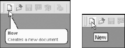
To change the size of the Tooltips or to turn off Tooltips altogether, go to Tools, Customize, Toolbars.
Note
The Tools

In SolidWorks 2007, it is easy to move, turn on and off, and add icons to toolbars. It is important to remember that different document types retain different toolbar settings; for example, the toolbars that you see with a part open are different from the toolbars that you see for drawings.
When you are working on parts, it is important to have both the Sketch and the Features toolbars active. When you are working on a drawing, you will never use the Features toolbar, but you will frequently use the Sketch toolbar. Likewise for assemblies, you may want to display some additional toolbars and eliminate others. For this reason, when you change from a part document to a drawing document, you may see your display adjust because the changing toolbars increase or decrease the amount of space that is required.
Note
It is best practice to set up the toolbars for each document type so that they take up the same amount of space—for example, two rows on top and one column to the right. This way, changing between document types is not so jarring, with the graphics area resizing for each change.
To move a toolbar, you can click with the cursor at the double bar on the left end of the toolbar, as shown in Figure 2.28. The cursor changes to a four-way arrow, and you can then drag the toolbar where you want it. Toolbars dock either vertically or horizontally. You can resize undocked toolbars so that they have rows and columns. This arrangement is typically used with the Selection Filter toolbar, which is often left undocked and compressed into a block that is three or four columns wide.
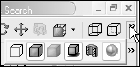
If the SolidWorks window is not wide enough for the toolbar to fit entirely in the screen, double arrows like those shown in Figure 2.29 display at the end of the truncated toolbar. When you click the double arrows, a flyout toolbar appears with the missing icons, as shown in Figure 2.30.
You can add or remove toolbars in several ways:
Right-click any toolbar, and then activate or deactivate the toolbar.
Click Tools

Right-click any toolbar, select Customize, and again select the toolbar from the Toolbars tab.
Click View
Note
There are two toolbar entries in the View menu: the topmost toolbars allow you to turn toolbars on or off, and the bottom toolbars toggle the display of all of the toolbars.
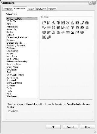
To add or remove icons from toolbars, you must open the Tools
You can use any toolbar as a flyout toolbar. Figure 2.32 shows the list of all flyout toolbars, which is exactly the same as the list of all toolbars. Flyout toolbars are a nice space-saving feature for tools that you use infrequently, but frequently enough to want to avoid going through the menus. To use a toolbar as a flyout, select it from the Flyout Toolbars list and drag it onto an existing toolbar. It displays with an arrow to the right. Clicking the arrow causes all of the tools to scroll out temporarily until you click either a toolbar icon or anything else.
To add icons to a flyout toolbar, temporarily show the regular toolbar that corresponds to the flyout toolbar, and add icons to the regular toolbar. When you are done adding or removing icons, turn off the regular toolbar; the changes are applied to the flyout.
Tip
If you want to create a separate toolbar, you can commandeer an existing one for your own purposes. For example, because I do not use the Tools toolbar, I have removed all of the regular icons from it and replaced them with relevant flyout toolbars, which I do use extensively. This allows me to consolidate space, and not have unused icons on my toolbars.
Full Screen mode enables you to quickly toggle the display so that only the graphics window and the Task pane display; the FeatureManager, menus, toolbars, and status bar are all hidden. Alternatively, you can hide just the FeatureManager or the toolbars.
In Full Screen mode, you can still access the menus by clicking the cursor along the top border of the window.
To toggle to Full Screen mode, press the F11 key.
To toggle the toolbar display, press the F10 key (see Figure 2.33).
To toggle the FeatureManager display, press the F9 key.
Note
Both Full Screen mode and the ability to hide the toolbars and the FeatureManager using hotkeys are new features in SolidWorks 2007.

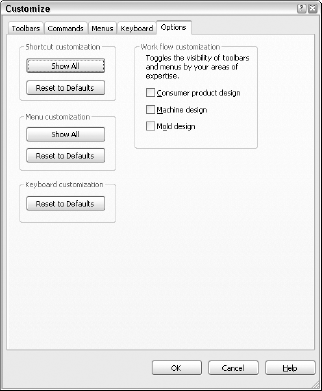
When you first install and run the SolidWorks software, you have the option to customize the interface using one of three pre-set option packages. Special menu and toolbar settings are made for Consumer Product Design, Machine Design, or Mold Design.
The three workflow customizations affect the interface as follows:
Consumer Product Design adds the Surfaces toolbar to the CommandManager.
Machine Design adds Sheet Metal and Weldments toolbars to the CommandManager.
Mold Design adds Surfaces and Mold Tools toolbars to the CommandManager.
Similar changes are made to the menus to hide or show menu selections as appropriate. You can find more information about hiding and showing menu items later in this chapter.
If you want to select a different option after the initial setup, you can go to Tools
The SolidWorks CommandManager works like a toolbar, but has much more flexibility. The CommandManager is divided into two areas, the Control Area and the Toolbar Area. The Control Area allows you to select which toolbar icons you want to display in the Toolbar Area. The default CommandManager is shown in Figure 2.35, and the Features and Sketch toolbars are listed in the Control Area. You can put any toolbar in the Control Area to save a lot of interface space.
At first, many users avoid using the CommandManager, but later come back to use it after seeing its flexibility and space-saving capabilities. I encourage you to give it a try. I was at first very skeptical of the benefits, until I used it for about a week, after which I was convinced.

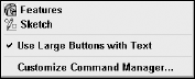
Many users are concerned about the amount of space that is taken up by the CommandManager when it uses the default settings. After all, it is supposed to save space, but it is so huge! You can make the icons the same size as normal icons and remove the descriptions. To do this, right-click the CommandManager and deselect the Use Large Buttons with Text option.
To add toolbars—such as Sheet Metal, Reference Geometry, or Tools—to the CommandManager, right-click the CommandManager, and select Customize CommandManager. This enables you to select additional toolbars. To reorder the toolbars in the Control Area, you must have Tools
You can use the CommandManager in two different ways. One way is to click the icon of the toolbar that you want to show in the Control Area, and then access the specific tools in the Toolbar Area. The other way is to use the Control Area icons as flyout toolbars, as shown in Figure 2.36.

Everyone has his or her own style of working. For example, some people like to use menus and others do not. An example of a tool that does not have a toolbar equivalent is View
The most frequently used menu items are in the View, Insert, and Tools menus. All of the menus shown in this section have all of the possible selections turned on. As a result, the View menu in Figure 2.37 may contain options that are not available on your computer. Customizing menus is covered later in this chapter.
The View menu is used primarily for turning on or off the visibility of entity types such as planes, sketches, or temporary axes. You can also do this by using hotkeys or by putting extra items on the View toolbar.

The Insert menu is used mostly for creating feature types for which you do not have a toolbar icon on the screen. For example, although the Move Face tool is only on the Mold Tools toolbar, it has many uses aside from mold design. You can find the Move Face tool on the Insert

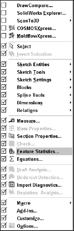
The Tools menu is used primarily for sketch entities or tools for which you have no icon on the screen. Several other commonly used tools, such as Measure, Equations, and Options, are also available in this menu. Figure 2.39 shows the complete Tools menu.

You can customize menus by adding or omitting items. By using the Customize Menu option at the bottom of any menu—including shortcut (right mouse button) menus—you can limit the items in any menu, by removing tools that you do not use. To bring back the removed items, you can either go back to the Customize Menu or go to Tools, Customize, Options and click the Reset to Defaults buttons for menu and shortcut customization. Be careful not to confuse this Customize menu selection with the Customize Menu selection on the Tools menu. Figure 2.40 shows the Tools menu being customized. Notice that several items at the top have been turned off.
The Tools
Keyboard customization is discussed later in this chapter.
Note
SolidWorks terminology for Shortcut Menus and Shortcuts/Keyboard customization is slightly confusing because of these two overlapping, yet unrelated, terms. For this reason, we will refer to Shortcut Menus as RMB (right mouse button) menus from here on, because this is the standard terminology among SolidWorks users. Shortcuts are also generally referred to as hotkeys among users.

SolidWorks cursors are context-sensitive, and change their appearance and function depending on the situation. Sketching cursors display a pencil and the type of sketch entity that you are presently sketching. Sketch cursors also display some dimensional information about the entity that you are sketching, such as its length or radius. Sketch cursor feedback is necessary for fast and accurate sketching.
Note
To learn more about sketch cursor feedback, see Chapter 4.
The Select cursor changes, depending the item over which you move it. Cursor symbols also help to remind you when selection filters are active.
The cursor is frequently available as an OK button. For example, after selecting edges for a Fillet feature, the RMB functions as an OK button.
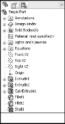
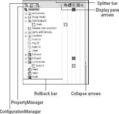
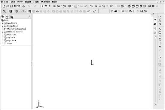
The FeatureManager window is the panel to the left of the screen that shows an ordered record of features describing how the part was built. SolidWorks users spend a fair amount of time using the FeatureManager to edit or inspect models. Figure 2.42 shows the FeatureManager for a simple model.
There is a splitter bar at the top of the FeatureManager that enables you to split the FeatureManager window into two windows, so that you can display the FeatureManager and another window, such as the PropertyManager. Small arrows in the middle of the right separator can collapse the FeatureManager to increase screen space. (The F9 key also collapses or opens the FeatureManager.) These elements are displayed in Figure 2.43.
You can open the Display-pane flyout from the FeatureManager by using the double arrows at the top-right corner, as shown in Figure 2.43. The Display pane helps you to visualize where colors, textures, transparency, or hidden bodies have been applied. Unfortunately, nothing can be changed from the Display pane, which would be the most intuitive. However, it is helpful when looking for colors that are applied to the model at some level other than the part level.
The Rollback bar at the bottom of the FeatureManager enables you to see the part in various states of history. All aspects of the FeatureManager are discussed in depth in Chapter 7.
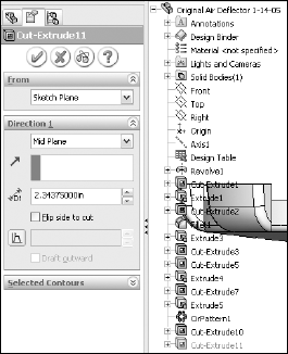
The PropertyManager is where most of the feature dialog boxes go, and where you can edit properties of selected items such as sketch elements. You can manually switch to the PropertyManager using the tabs on the top of the Display panel. The left-most icon is the FeatureManager tab, the middle one is the PropertyManager tab, and the one on the right is the ConfigurationManager tab. Other icons may appear in this area for drawings, or if you have add-ins such as PhotoWorks or Animator turned on.
One of the benefits of putting dialog boxes in the PropertyManager is that it saves a lot of space on the screen. On the other hand, you will often need to make a selection from the FeatureManager at the same time that the PropertyManager pops up and takes its place. This automatic pop-up behavior is controlled by a setting in the Tools
By default, the Task pane sits to the right of the SolidWorks screen, although you can dock it on the left side or leave it undocked entirely. When the Task pane is expanded, you can collapse it by clicking outside of it. If you want to keep it open, click the pushpin in the upper-right corner of the pane. The Task pane is shown in Figure 2.45.

The Task pane is the home for several panels:
SolidWorks Resources: These are useful links for templates, tutorials, tech support, news, GlobalSpec search, Tip-of-the-Day, and other resources.
Design Library: This includes locally stored libraries, Toolbox, and 3D Content Central.
File Explorer: This is a Windows Explorer–like interface that you can use to browse for files.
SolidWorks Search: If you have installed the Windows Desktop Search with SolidWorks 2007 and indexed your files, you can perform searches that include filename and custom properties.
View Palette: This palette allows you to visually select views and drag them onto a drawing sheet.
The status bar is a non-intrusive way in which SolidWorks communicates information back to the user. It is located at the bottom of the screen, and you can enable it from the View menu. Figure 2.46 shows the status bar in action.
The status bar can display the following information, indicators, and icons:
Progress as parts, assemblies, or drawings load
Tooltips for icons
Measurements
Sketch status for an active sketch
In-context editing
Suspend Automatic Rebuilds
Icons that allow you to turn Quick Tips off or on
Sheet scale for drawings
Cursor position for drawings and sketches
Whether you are editing the sheet, sheet format, or view of a drawing
This is a tool specifically for people who are coming to SolidWorks from AutoCAD. As the name suggests, it adds a command line to the bottom of the SolidWorks window, that works like the AutoCAD command line in most respects. The available commands are somewhat limited compared to those that are available in AutoCAD. This tool only functions in the 2D sketch mode, on a drawing sheet, or in a drawing view; it does not work in a 3D sketch. The 2D Command Line Emulator is shown in Figure 2.47.

Available sketch tools in the 2D Command Line Emulator include: Align, Arc, Array, 'Cal, Chamfer, Chprop, Circle, 'Color, Copy, DDcolor, Dim, Dist, Ellipse, Erase, Exit, Extrude, Fillet, 'Grid, Line, List, Massprop, Mirror, Move, Offset, 'Ortho, 'Osnap, 'Pan, Plot, Point, Polygon, Qsave, Rectangle, 'Redraw, 'Redrawall, Revolve, Rotate, Save, Saveas, 'Snap, Spline, Trim, U (undo), 'Units, 'View, and 'Zoom. Commands that are preceded by an apostrophe (') can be used as transparent commands, without exiting an active command. Notice that even the cursor changes to crosshairs.
Note
The best way to learn a new software package is to embrace the new way, not to cling to the old way. Although you may find the 2D Command Line Emulator more comfortable to work with, you will not achieve the same results as you will with the SolidWorks default sketching mode. For example, the resulting sketch entities created using the 2D Command Line Emulator are not constrained in any way, and the endpoints do not even merge. You can turn off the 2D Command Line Emulator by going to Tools, Add-ins.
As engineers and designers, we all like to tinker with things to optimize efficiency and to apply our personal stamp. When it is installed, the SolidWorks interface is functional, but not optimal. In the previous pages, we have discussed managing and customizing toolbars and menus. In the remainder of this chapter, we discuss more about customizing the interface, and suggest some strategies that you might use to help customize your work environment.
You need to be aware of a few things before you change all of the standard colors in the SolidWorks interface to whatever strikes your fancy. The first is that SolidWorks does not automatically alter text color to contrast with your background. As a result, if you set the background to black, and the text is black, you won't be able to see the text. This may seem obvious to some people, but AutoCAD automatically changes text color to contrast with the viewport background, and so AutoCAD users may take this functionality for granted.
Some colors should be avoided for the background, or you should at least make some other changes if you choose these colors. Black is used with fully defined sketches, dimensions, FeatureManager text, and annotations. Blue backgrounds often mask the underdefined sketch color. Bright green backgrounds can cause problems with seeing selected items. Bright red, aside from being a terrible color to stare at all day, also does not contrast well with some of the red highlights and error colors.
You might say that whatever color background you select, it makes items or features difficult to see. For this reason, many users choose a gradient background, which allows you to pick colors where items are always visible on one half of the screen or the other. Staring at a white screen all day can be uncomfortable for your eyes, so pick colors that allow you to see everything with "reasonable" contrast, yet that are not glaringly bright. Very high contrast is hard on the eyes, and low contrast may make it difficult to distinguish items on the screen.
In addition to colors and gradients, you can use an image as the graphics window background. This gives you a wider range of customization capabilities, and several sample images are already available in the default settings.
You can easily customize many aspects of the SolidWorks interface, including:
Toolbars
Menus
Background colors or images
PropertyManager skins
Task pane location
Hotkeys
Macros
Custom application programming
Whether or not you should customize each of the above items depends partially on how much time and energy you have to spend, as well as how much money you are ready to dedicate in the case of custom programming.
Some of us old-timers prefer to use the keyboard over the mouse. If your hand-eye coordination is as bad as mine, you may also choose this approach. I can type without looking at the keyboard, but when I use the mouse, it takes me a few seconds to aim at an icon and hit it accurately. This means that I customize SolidWorks to use as many hotkeys as possible, and remove icons from the interface if I have them on a shortcut. Unfortunately, my memory is as bad as my eyesight, and so remembering 75 hotkey commands is a bit of a problem. I admit to having a printed list of hotkeys taped to the side of my monitor. While I know that needing to read the list to find a particular hotkey defeats most of the purpose of using them in the first place, I just accept it as a learning aid.
I generally do not advocate trying to standardize a hotkey scheme across multiple users, unless the users all agree to it. The underlying reason for writing a section entitled Hotkey Approaches is that everyone remembers things differently in the first place, and people have different tolerance levels for various irritations.
Any command that I use more than a few times an hour is worth assigning to a hotkey. I like to use alliteration when assigning keys to help with my faulty memory. Most-frequently used commands are assigned single-letter hotkeys, and less-frequently used commands are assigned combinations. Thus, Tools Options is linked to O, Measure to M, Select Vertex to Shift+V, and Curve Projected to Ctrl+J (Ctrl+P is the Windows standard for the Print command).
Other people like to group keys into easy-to-reach combinations, and so the Q, W, A, S, Z, and X keys are often assigned first for right-handed mouse users.
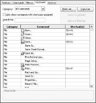
Hotkeys are assigned and organized in the Tools
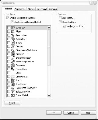
Because the list of commands is so long, there is a Search function available, and a drop-down arrow that makes visible only the commands from a selected menu. The list of commands is organized by menu name, and the menus are listed as they occur in the interface. Fortunately, here on the Keyboard tab, SolidWorks allows you to sort using the column headers to list the menus, commands, or hotkeys in alphabetical order, simply by clicking the column header. This is a highly usable interface.
Note
This method for organizing and assigning hotkeys is new for SolidWorks 2007.
Moving between the mouse and the keyboard can be bothersome and time consuming. In addition to the hotkey approach, you can use another keyboard method to save time. Many users become adept at using the Alt-key combinations to invoke menu items. Most menu items in Windows applications contain a single underlined letter.
To access a top-level menu, you can hold down the Alt key and press the underlined letter for that menu, and then just press an underlined letter in the menu to access specific commands. This technique enables you to navigate most of the interface without using the mouse. For example, to exit SolidWorks, instead of using the mouse to click the red X in the upper-right corner, you could press Alt+F, X. In Figure 2.49, you can see that the F in File is underlined, as is the X in Exit.

Note
The SolidWorks documentation terminology becomes further confused when talking about accelerator keys. It says that the general class of keys is called Shortcuts, which can be either accelerator keys or keyboard shortcuts. How these are distinguished from Shortcut Menus is not clear. Again, for our purposes in this book, we refer to the shortcut menus as RMB (right mouse button) menus, accelerator keys as Alt-keys, and keyboard shortcuts as hotkeys, which is more in line with standard usage than the documented terminology.
In order to maximize valuable space on the monitor, many SolidWorks users strive to minimize the number of toolbar icons on the screen, or confine it to two rows of toolbars. You can do this by using the CommandManager, flyout toolbars, and hotkeys, and removing unused icons, as well as the other techniques discussed here.
If you have never used a Spaceball or equivalent view-manipulation device, you should consider it. They are wonderful devices and do far more than just spin the view. Most of the devices also have several programmable buttons that you can link to menu items. They can move drawing views, and parts within assemblies, and even manipulate selected objects in other Office applications and Web browsers. In addition, some game controllers, such as the Microsoft Sidewinder, are inexpensive and offer almost endless possibilities with button programming.
I have not yet come across a tablet that works well for SolidWorks command input. I believe that tablets have the same shortcomings as mice because they both require that you look at what your hands are doing.
Macros are short snippets of programming code that have a particular function. Most macros are small and intended for simple tasks that are repeated many times, such as drawing a rectangle centered on the origin of a selected plane, or changing selected dimensions to four decimal places. Macros may be recorded, written from scratch, or a combination where you record a particular action to be used as a starting point, and then embellish it manually from there. Recorded macros may not always record the parts of the action that you want to make into a macro, but you can edit them manually to include anything that you can program with VBA (Visual Basic for Applications), which is included with the base SolidWorks package at no extra cost.
Note
Macros are covered in more detail in Chapter32. Appendix C also contains sources for macros and macro-related help.
To access macros by using hotkeys, follow these steps:
Make a folder in your SolidWorks installation directory called "macros".
Copy macros into this folder.
Start (or restart) SolidWorks.
Go to Tools
Scroll to the bottom of the list under the Macros category, and assign hotkeys as you would for standard SolidWorks commands.
Whether you are skilled at writing or recording macros, or you are just using macros collected from other people, they can be huge time savers and offer functionality that you would not otherwise be able to access.
Once you have set up your menus and toolbars, worked out all of the custom colors, figured out your hotkey usage, and connected your macros, you don't want to lose these settings when you reinstall the software or move to a different computer. Another user may want to share your settings, or you may want to transfer them to your home computer (for modeling the new deck or the doghouse, of course). Fortunately, these settings are very portable.
You can use the Copy Settings Wizard to save these settings out to a file. Access the wizard through Start, Programs, SolidWorks 2007, SolidWorks Tools, Copy Settings Wizard. This creates a file with an *.sldreg file extension. You can restore settings by double-clicking this file on a computer that has SolidWorks installed on it.
The SolidWorks settings are actually Windows registry settings. The file that is saved by the wizard is just a registry file that has a different extension to prevent it from being applied too easily. Saved-out registry files have a *.reg file extension, and are integrated into the registry by simply double-clicking them. If you are not familiar with the Windows registry, you should not make direct changes, because even small changes can cause serious problems with your operating system or even hardware. The settings that are saved out by the Copy Settings Wizard are safe to transfer between computers. In order for the Copy Settings Wizard to work, you need to have Administrator-level access to your computer. The Copy Settings Wizard is shown in Figure 2.50.

In SolidWorks, as in other areas of life, things can become chaotic. You may sometimes have the luxury of working on a single part at a time, but more often, you will find yourself with several models open at once. This is a common situation for most users. Fortunately, SolidWorks has several methods for dealing with "information overload," to help you sort through it all.
Like most other Windows applications, SolidWorks can arrange the open document windows in one of several ways that are available through the Window menu, as shown in Figure 2.51:
Cascade: Most useful for accessing documents that are to be edited one by one.
Tile Horizontally: Most useful for wide and short parts.
Tile Vertically: Most useful for tall, narrow parts, or documents where you want to compare items in the FeatureManager.
Arrange Icons: When windows are minimized to icons, this menu selection arranges the icons neatly, starting in the lower-left corner of the window.

The images in Figure 2.52 show the window-management settings listed above.

Also remember that you can use the F9 key to close the FeatureManager, and the F10 key to remove the toolbars to create extra interface space when arranging several windows in the graphics window.
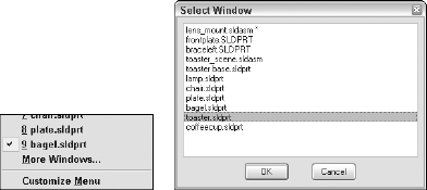
You can use several techniques to change from one window to another. By clicking on the Window menu, you can view a list of open document windows, as shown in Figure 2.51. You can then select the desired window directly from this menu. If more than a few windows are open, a More Windows option appears at the end of the list, as shown in Figure 2.53. Clicking on this option brings up a separate window that enables you to select from the complete list.
When a smaller number of windows are open, a simpler way to change windows is to press Ctrl+Tab. This is a Windows standard technique that also works in other Office applications. Ctrl+Tab takes you in one direction in the list of open windows, and Ctrl+Shift+Tab takes you in the opposite direction through the list.
By this point, you really have not learned much about making parts, assemblies, and drawings in SolidWorks, but you have learned quite a bit about using the interface. In this tutorial, you get some hands-on practice at making the changes that we have discussed in the rest of this chapter. The rest of the book also uses the settings that you create here.
This tutorial is intended to reinforce the following skills:
Adding and removing toolbars
Adding and removing toolbar buttons
Adding and removing items from drop-down and RMB menus
Setting up the CommandManager
Setting up hotkeys
Linking a hotkey to a macro
Changing interface colors
Regardless of what your initial settings are, you do not want to lose them. Before you start to make changes to your system, you should save out the existing settings to a file from which they can be recovered. You can do this using the Copy Settings Wizard, as shown in Figure 2.54.

To use the Copy Settings Wizard, follow these steps:
Close SolidWorks.
Click Start
Select Save Settings, and click Next.
Enter a location and a name for the file.
Select the items that you would like to save. For the purposes of this tutorial, make sure that the following options are selected: Keyboard Shortcuts, Menu Customization, Toolbar Layout, and All Toolbars.
Click Finish.
Browse to the location where you saved the file and make sure that it is there.
You can set the interface back to the default settings using one of two methods. The first method, editing the Windows registry, may not be available to all users. It requires Administrator access to your computer and a good familiarity with Windows.
Warning
Editing the Windows registry can be dangerous if you make a mistake. Do not attempt this method is you have any doubts about what you are doing.
To set SolidWorks back to its default settings, follow these steps:
Close SolidWorks.
Click Start
Type regedit, and click OK.
Browse to HKEY_CURRENT_USERSoftwareSolidWorksSolidWorks 2007 or the appropriate folder for the version that you are using.
To return all settings in SolidWorks back to default, delete the entire SolidWorks 2007 folder.
Close the Registry Editor.
The folder is recreated when SolidWorks starts up again, and is populated with default values.
The second method, which is less risky but less complete, is to go to the main locations and use the tools provided to return settings to their defaults. Restart SolidWorks and create a new blank document (you cannot display the Customize dialog box without a document open). To access the resets for the interface, do the following:
Click Tools
Click Tools
Click Tools
Click Tools
Click Tools
Now that you have restored the default settings, you can begin customizing the interface with the CommandManager. To do this, RMB click anywhere on the CommandManager and deselect the Use Large Buttons with Text option, as shown in Figure 2.55. When you have done this, the check mark should no longer appear in front of the option.
Next, add some toolbars to the Control Area of the CommandManager, as follows:
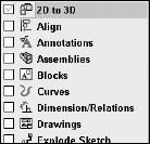
Again, RMB click the CommandManager, and select Customize CommandManager.
Select the Surfaces, Sheet Metal, and Annotations toolbars from this list, which is partially shown in Figure 2.56. Deselect the Sketch toolbar.
Click outside of the list; the list closes and applies the changes you made.
Click the Features toolbar button in the Control Area of the CommandManager, and make sure that the Features toolbar buttons appear in the Toolbar Area to the right.
RMB click any toolbar other than the CommandManager, and select Customize; this brings up the Tools
Reorder the toolbars in the Control Area of the CommandManager so that the Annotations toolbar comes first. When you are done, The CommandManager should look like Figure 2.57. Leave the Customize dialog box open.
Make sure that the Toolbars tab of the Customize dialog box is displayed.
Turn on the Sketch and Tools toolbars.
Place the Sketch toolbar to the right of the Task pane, and the Tools toolbar just above the Task pane.
Drag the Reference Geometry and Curves flyout toolbars from the end of the Features toolbar in the CommandManager over to the Tools toolbar, as shown in Figure 2.58. Use the Tooltips to identify the buttons.

The display should now look like Figure 2.59. Close the Customize dialog box.
If you always do the same types of work, or more importantly, never do certain types of work, then you might consider customizing some menus to remove items that you never use. Customization applies to both the main drop-down menus and the context-sensitive RMB menus. To customize a menu:
Click Insert
Turn off the menu items Sketch from Drawing, DXF/DWG, Object, Hyperlink, and Picture, as shown in Figure 2.60. Click anywhere outside of the list to close it.
Click the Insert menu to ensure that the deselected items have been removed.
RMB click the Right plane in the FeatureManager.
Select Customize Menu.
Turn off Section View. Click anywhere outside of the list to close it.
RMB click the Right plane to verify that Section View has been removed.

Edit the colors used in the interface:
Click the Select Color Scheme tool from the Standard toolbar. Each time you click this tool, the background color changes to a new scheme.
Click the drop-down arrow to the right of the button to see the entire list. Select another scheme from the list.
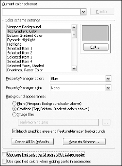
Click Tools
Change the viewport background color to white (preview thumbnails use this background color).
Adjust the top gradient and bottom gradient colors to your personal taste, but choose colors that are both functional and attractive.
Set the Background Appearance toggle to Gradient.
Make sure that the Match Graphics Area and FeatureManager Backgrounds option is selected.
Deselect the Use Specified Color for Shaded With Edges Mode option. This makes the edges of models a similar hue to the part itself, rather than the cartoonish-looking black edges.
Click the Save As Scheme button, and save the scheme with your name or another filename that is easily identifiable.
Click OK to close the Tools
Again, click the drop-down list next to the Select Color Scheme tool; your new custom color scheme should now have been added to the list.
For many users, hotkeys are an integral part of the everyday experience of using SolidWorks. You can easily assign hotkeys and manage the assignments by following these steps:
Click Tools
In the Search For text box, type Options.
Click in the Shortcut column, and type O.
Click again in the Search For text box, and type Customize.
Click in the text box next to the Tools
Click OK to exit the Customize dialog box.
Press the O key to bring up Tools
Press Ctrl+T to bring up Tools
Press Alt+F, and then press X to exit SolidWorks.
Macros are covered in Chapters 34 and 35, but the following steps show you how to link a macro to a hotkey:
Note
You can use the macro called rectangle.swp, located on the CD-ROM.
Find your SolidWorks installation directory. By default, this directory is C:Program FilesSolidWorks.
Create a folder called Macros in the SolidWorks directory and put the rectangle.swp macro in it.
Start SolidWorks.
Create a new blank part document.
Press Ctrl+T to access the Customize dialog box.
Click the Keyboard tab.
In the Search For text box, type rectangle.
Click in the Shortcut column next to the listing with the Category of Macros, and press R.
Click OK to exit the Customize dialog box.
Press R. The rectangle macro runs and draws a sketch rectangle on the Front plane, centered on the origin.
Press Ctrl+S to access the Windows standard hotkey for the Save command. Name the part rectangle.sldprt and save it to a workspace directory.
Press Alt+F and then X to exit SolidWorks.
The use of Alt-keys and hotkeys is somewhat exaggerated in this tutorial, but it is intended to get you used to working with them.
The SolidWorks interface is quite busy, and you can access most items in multiple ways. This allows you to choose how you work, whether through toolbars, the CommandManager, or menus, among other choices. The fact that SolidWorks is so tightly integrated into Windows means that in most cases, you know what to expect from the interface, and much of your knowledge from using other applications is transferable.
The SolidWorks interface is also customizable through all of the standard Windows methods, such as rearranging toolbars, customizing menus and hotkeys, and changing background colors and skins. If you spend a significant amount of your workweek using this software, you want to take some time to configure it for efficiency and comfort. Because of the complexity of the interface and the myriad ways in which you can use it, each user is expected to create an interface that looks a little bit different from anyone else's.