
IN THIS CHAPTER
Opening a sketch
Identifying sketch entities
Inferencing in Sketch
Sketch settings
Sketch blocks
Tutorial: Learning to use sketch relations
Tutorial: Using Blocks and Belts
This is where the fun begins, or begins to begin. To me, training animals has always been fun, especially when the animal begins to respond to my instructions. Learning SolidWorks is like working with an animal that has already been trained. You know it is supposed to respond to you in certain ways, but there is always this little thrill of having communicated with something outside of yourself when it actually responds with a predicted behavior. This is not to say that it is surprising; it is just somehow a little thrilling. SolidWorks programmers have created an animal that responds to your input with intelligence and comprehension.
So far in this book, we have looked mainly at settings and setup, which is pretty mundane business. However, here we begin to build models, simple at first, but gaining in complexity and always demonstrating new techniques and features that build your modeling vocabulary. Beyond this, we move into putting the parts together into assemblies, which helps to make the "pretty pictures" look like something useful. Finally, we use the parts and assemblies to create drawings.
Several basic facts about sketches may be helpful before we start. While a part may have many sketches, only one sketch can be open at a time. This is due in part to the history-based nature of the software because every entry in the FeatureManager tree must be edited in the order in which it sits in the tree.
While you can create both 2D and 3D sketches, you will use 2D sketches most of the time. When referring to a generic sketch, a 2D sketch is always assumed. You will use 3D sketches in specific situations, and they will be explicitly called for when needed.
Note
We discuss 3D sketches in detail in Chapter 31.
When you open a sketch, several tools become unavailable. For example, you cannot apply a Fillet feature while a sketch is open. Conversely, there are several things that you cannot do until you open a sketch. When I used to teach SolidWorks classes for a reseller, I had only one rule: you were not allowed to throw the monitor out the window because of frustration until you checked to see if you were in or out of Sketch mode and if the selection filter was turned on. These features are two very common sources of frustration for new users.
There are several indicators that let you know when you are in Sketch mode:
The top bar of the SolidWorks window displays the text, Sketch X of Part Y.
The lower-right corner of the status bar displays the text, Editing Sketch X.
The Confirmation Corner displays a sketch icon in the upper-right corner of the graphics window.
The Sketch toolbar button now displays the text, Exit Sketch, and is pressed in.
The red sketch Origin displays.
If you are using the grid, it displays only in Sketch mode.
While most users find the sketch grid to be annoying and distracting, when teaching, I always used the grid to remind students when they were in Sketch mode. If you find that you forget or would like a visual cue, the sketch grid is a useful, if less than fashionable, option.
There are several ways to open a new sketch in SolidWorks:
Click a sketch entity toolbar button from the Sketch toolbar; SolidWorks prompts you to select a sketch plane. When you select the plane, the sketch opens.
Preselect a plane or planar face and then click either a sketch entity button or the Sketch button.
Right-mouse button (RMB) click a plane or planar face and select Insert Sketch.
You can open existing sketches in several ways:
RMB click a sketch in the FeatureManager or graphics window, and select Edit Sketch.
Select a sketch from the FeatureManager or graphics window, and click the Sketch button on the Sketch toolbar.
Double-click a sketch with the Move/Size Features tool active.
The first step in creating most SolidWorks parts is a sketch. This will usually be a 2D sketch, although 3D sketches are also used and are discussed in Chapter 31. A 2D sketch is simply a collection of 2D lines, arcs, and other elements that lie together on a plane; it usually also contains relations and/or dimensions between the entities.
SolidWorks sketch entities include many types, some of which you will use all of the time, and some of which you may not use, even if you spend years working with the software. Here we will identify each entity type so that you see it at least once, and know that it is available if you need it at some point.
The default buttons on the Sketch toolbar are identified first, followed by the rest of the entities that you can access through Tools
Horizontal, Vertical, and Aligned: You can create dimensions in three ways, as shown in Figure 4.1:
By selecting a line and placing the dimension
By selecting the endpoints of the line and placing the dimension
By selecting lines at the ends of the line and placing the dimension
Selecting the line is the easiest and fastest method. Selecting the lines on the ends is not recommended because if you delete either of the selected lines, the dimension is also deleted.
You can use the first and second techniques for the angled line shown in Figure 4.1 to create any of the three dimensions shown. You can do this by dragging the cursor while placing the dimension until the witness lines snap to the orientation you want.
Tip
To lock the orientation of a dimension while moving the cursor to place the actual dimension value, RMB click. To unlock it, just RMB click again.

In this case, the third technique locks you into the horizontal orientation because of the orientation of the selected lines.
Warning
When you select end lines to establish a dimension instead of endpoints, both of the end lines will gain an implied relation that prevents them from moving as you might predict. In the case shown in Figure 4.1, neither of the end lines can be angled unless you remove the dimension.
Another issue that arises for adding dimensions to end lines is that if you delete either of the end lines, the dimension is also deleted. This is not true for the first and second techniques, where as long as the endpoints remain, the dimension also remains.
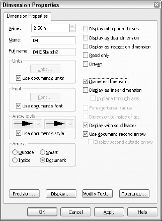
Radial: You create the dimension by selecting an arc and placing the dimension. If you want a radial dimension of a complete circle, you must RMB click the dimension after you create it, select Properties, and deselect the Diameter Dimension option, as shown in Figure 4.2.
Diameter: You can create the dimension by selecting a complete circle and placing the dimension. If you want a diameter dimension for an arc, use the Dimension Properties dialog box shown in Figure 4.2 and select the Diameter Dimension option.
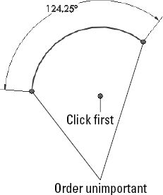
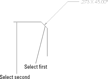
Angle: You can create the dimension in one of two ways. If the angle to be driven is between two straight lines, simply select the two straight lines and place the dimension. If you are creating an included angle dimension for an arc where there are not necessarily any straight lines drawn, then with the Smart Dimension tool active, first select the vertex of the angle, and then the two outlying points, as shown in Figure 4.3.
Arc Length: You can create the dimension by selecting an arc and its endpoints with the Smart Dimension tool.
Click-Click: Used for drawing multiple connected end-to-end lines. Click and release the left-mouse button to start the line; each click-and-release ends the previous line and starts a new one. Double-click, press Esc, or deselect the Line tool to end.
Click-Drag: Used to draw individual or unconnected lines. Click, drag, and drop. The first click initiates the line, and the drop ends it.
Alternate methods for drawing lines include horizontal, vertical, angle, and infinite lines. The interface for these options displays in the PropertyManager, as shown in Figure 4.4.
Horizontal, Vertical: These settings require you to select a starting point, and an ending vertical or horizontal position. There does not seem to be any compelling reason for you to use this instead of the regular line command.
Angle: Enables you to specify an angle and drag a line at this angle. Again, I can find no compelling reason to use this tool.
Infinite Lines: This is truly puzzling. SolidWorks parts have a working space limited to 1000 meters on a side, centered on the Origin. Infinite lines extend well beyond this, although you cannot draw or dimension a regular line outside of this box. I have not come across a compelling use for this feature, and I am quite sure that it was added only to appease unrepentant AutoCAD users.

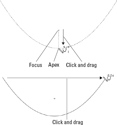
Center Creation: Click the center of the circle and drag the radius. The Circle PropertyManager calls this function center creation.
Perimeter Creation: This only creates tangent relations with other entities in the current sketch, and so if you are building a circle from model edges or entities in other sketches, you need to apply the relations manually. SolidWorks calls these functions perimeter creation. To create a circle using this technique, you must select the Perimeter Creation option from the Circle PropertyManager window after clicking the Circle tool. There is also a separate Perimeter Creation toolbar button, and a menu selection for Tools

Tangent to Two Entities: Start the circle with the cursor near one line in the sketch. A Tangent symbol appears by the cursor with a yellow background. Click and drag the diameter to the second tangent entity, where a similar cursor symbol should appear. Release the mouse button and RMB click the green check mark icon. This process is shown in Figure 4.5.
Tangent to Three Entities: Use the process for Tangent to two entities, but omit the RMB click of the green check mark icon. After dropping on the second tangent, drag again to the third tangent entity.


Another way to create a tangent arc is to start drawing a line from the end of another sketch entity, and while holding the left mouse button, to press the A key, or to return the cursor to the starting point and drag it out again. This method can be difficult to master, but it saves time when compared to any of the techniques for switching sketch tools.


Splines are used mainly for freeform complex shapes in 2D and 3D sketches, although you can also use them for anything that you would use other sketch elements for.
You can also use the sketch point as a virtual sharp. If two sketch entities do not actually intersect because of a fillet or chamfer, selecting the two entities and clicking the Point tool creates a point at the location where they would intersect if they were extended. This is useful for dimensioning to the sharp. Virtual sharp display is controlled by a Document Property setting that is described in more detail in Appendix B.
When the Add Relation PropertyManager is active, you do not need to use the Ctrl key to select multiple entities. You also do not need to clear a selection before making a new selection for the next relation. These two reasons sound minor, but if you have a large number of sketch relations to apply, the workflow goes much more smoothly using this tool than the default method.

The options available in the Offset Entities interface are as follows:
Add Dimensions: Constrains offset sketch entities. Instead of the On Edge relations, Offset Entities creates an Offset sketch relation that cannot be recreated manually.
Reverse: Changes the direction of the offset.
Select Chain: Selects continuous end-to-end sketch entities.
Bi-directional: Offsets to both sides simultaneously.
Make Base Construction: If you are offsetting sketch entities within the active sketch, this option converts the original sketch entities to construction sketch geometry.
Cap Ends: Is available only when you have selected the Bi-directional option. Capping the ends with arcs is an easy way to create a slot from a sketch of the centerline. This function works with all sketch entities, and so it is not limited to straight slots. Figure 4.11 shows examples of the Cap Ends option.
Warning
The Offset Entities command may fail if the offset distance is greater than the smallest radius of curvature, and you are attempting to offset to the inside of the arc.

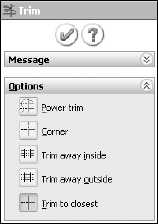
Power Trim: Trims by dragging a cursor trail over multiple entities. The entities that you drag the cursor over are trimmed back to the next intersecting sketch entity. Each time you trim an entity, a red box is left behind that remains until you trim the next entity. If you backtrack with the cursor and touch the red box, this trim is undone. This option is best used when you need to trim a large number of entities that are easy to hit with a moving cursor. Figure 4.13 shows the Power Trim feature in action.
You can also use power trim to extend sketch entities along their paths by dragging the endpoints. Regular dragging can also change the position or orientation of the rest of the entity, but by using the Power Trim feature, you affect only the length.
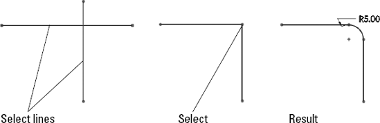
Corner: Trims or extends two selected entities to their next intersection. When you use the Corner option to trim, the selected portion of the sketch entities is kept, and anything on the other side of the corner is discarded. Figure 4.14 shows two ways that the Corner option can work.
Trim Away Inside: Trims away selected entities inside a selected boundary. The boundary may consist of a pair of sketch entities or a model face (edges of the face are used as the boundary). Only entities that cross both selected boundaries (or cross the closed loop of the face boundary twice) can be trimmed. This option does not trim a closed loop such as a circle, ellipse, or closed spline.
Trim Away Outside: Functions exactly like the Trim Away Inside option, except that sketch entities outside of the boundary are discarded. The Trim Away Inside and Outside option are illustrated in Figure 4.15.
Trim to Closest: This is the default setting. Clicking on a sketch entity will:
Trim it back to the next entity if there is only one crossing entity.
Trim between two crossing entities if there are more than one.
Delete the entity if there are no crossing entities.
In all cases, the selected section of the entity is removed.
The Trim to Closest option can also extend by dragging one entity to another; if an intersection is possible, the first entity is extended to the second entity. Figure 4.16 illustrates how the Trim to Closest option functions.


To draw a rectangle at an angle, click one corner of the rectangle, and then drag a side connected to that corner. Then click and drag the length of the second direction.
To draw a parallelogram (adjacent sides are not perpendicular, but opposite sides are parallel), draw the first side of the parallelogram in the same way as the first side of the rectangle, but hold down the Ctrl key when dragging the second side; you can set the angle as well as the length.


Note
You should use sketch patterns as little as possible. For much the same reasons that fillet features are preferred over sketch fillets, pattern features are also preferred over sketch patterns. Sketch patterns are not as editable or as flexible as feature patterns. They solve slowly, especially when you pattern a lot of entities. Best practice is to avoid sketch patterns unless there is no alternative.


Both the left- and right-mouse buttons have special functions, which change when the cursor is moved over the three knots on the special Origin. The RMB allows you to mirror or rotate the sketch, and the left-mouse button, or LMB, allows you to move the Origin or move the sketch.
This function has some limitations when you use it with sketches that have external relations. Certain functions may be disabled, or a warning message may appear, saying that you need to remove external relations to get a particular function to, well, function.

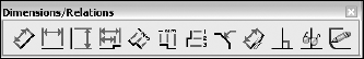
The Dimensions/Relations toolbar has a few tools that we have already seen, but as the name suggests, it also contains tools that will either help you to create or investigate dimensions and sketch relations. Figure 4.23 shows the default toolbar, but in the following pages, we look at all of the available tools that are available through Tools

Note
If a line is not selected as the zero reference entity, the Ordinate Dimension feature defaults to a Horizontal Ordinate.
You can remove Ordinate Dimensions from the common alignment by RMB clicking the dimension and selecting Break Alignment.
Ordinate Dimensions will jog automatically if SolidWorks senses that the dimensions are getting too close to one another. You can also jog them manually.
After you create the Ordinate Dimension set, you can add to it by accessing the Add to Ordinate command through the RMB menu.
All of these options for Ordinate Dimensions are shown in Figure 4.25.

Not all of the listed options are available in the model sketch environment; some are available only in drawings.
Note
While the Auto Dimension feature can clearly save you a lot of time dimensioning parts on a drawing, it does not necessarily use the best dimensioning practice for manufacturing drawings. This tool is best used in situations when baseline dimensions are appropriate.
Warning
As with any automatic function, there are times when automatic relations will do things that you do not expect or want. While you are sketching, it is recommended that you watch the cursor and the relations that it automatically applies.
While sketching, symbols appear on the cursor to show that a relation will automatically be created. These symbols have a yellow background, and will apply horizontal, vertical, coincident, tangent, parallel, and perpendicular relations. Figure 4.27 shows two situations where automatic relations are applied—a horizontal and a tangent relation.

Although Inferencing and Automatic Relations are often confused, even by experienced SolidWorks users, these functions are not the same. Inferencing refers to the blue dotted lines that display in Sketch mode when the cursor aligns with endpoints, centerpoints, or the Origin. Inferencing does not create sketch relations, with one exception. If the cursor is aligned to one side of the endpoint of another line, and you draw a horizontal line, then an automatic Coincident relation is applied between the line and the endpoint. This also holds true if the cursor starts above or below the point and you draw a vertical line.
When the cursor displays a small symbol with a yellow background, this means that an automatic relation is going to be applied. If the relation symbol has a white background, the relation is inferenced, but not applied as an actual sketch relation. The symbols with the blue background are relations that have been applied to existing sketch entities. The symbols look the same, regardless of background color.
The following are the symbols for the various inferences, automatic relation cursors, and applied sketch relations. The difference between the three types is simply the background colors, white, yellow, and blue, respectively.
Note
These relations are defined in the Sketching with Parametrics section of Chapter 1.
In addition to sketch tools, another important aspect of controlling sketches is sketch settings. Sketch settings are found in two different locations. The first location is at Tools
Note
The sketch settings at Tools
Automatic Relations is covered in depth in the Dimensions/Relations toolbar section.
Automatic Solve is turned on by default. As you make changes to a sketch by adding relations or changing dimensions, SolidWorks automatically and immediately updates the sketch to reflect the changes. When the Automatic Solve setting is turned off, these changes are deferred until you exit the sketch or turn the Automatic Solve setting back on. The setting can be useful to prevent intermediate solutions (for example, when half of the changes are made) that may cause problems with the sketch, and when you are confident that the outcome will be correct.
If you import a large drawing from the DXF or DWG formats, these drawings import as sketch entities into either a SolidWorks sketch or a drawing. SolidWorks may automatically turn off the Automatic Solve setting for performance (speed) reasons on files of this type.
Enable Snapping is turned on by default. It enables the cursor to snap to the endpoints of existing sketch entities to help you make cleaner sketches. When you turn this setting off, Automatic Relations is also disabled (although the icon for the setting remains depressed, Automatic Relations are not created).
No Solve Move is discussed in the Sketch toolbar section.
Detach Segment on Drag is turned off by default. When you turn this setting on, the Detach Segment on Drag feature enables you to pull a single sketch element away from a chain of elements. For example, if you have a rectangle and you want to detach one of the lines from the rest of the rectangle, without using this setting, you would have to draw extra geometry and then trim and delete lines in order to release the endpoints.
Note
It is recommended that you leave this setting off. Turn it on only when you need it, and then immediately turn it off again. This setting can be hazardous for everyday use, since it enables you to simply drag sketch elements that may be otherwise fully defined.
Override Dims on Drag is off by default. When you turn this setting on, it enables you to drag fully defined sketch geometry, and the dimensions will update to match the dragged size. This is another setting that you should use sparingly. It can be useful for doing concept work, but you should leave it off when working with production data for obvious reasons.
Sketch blocks are collections of sketch entities that can be treated as a single entity. You can use sketch blocks in parts, assemblies, and drawings. To create a sketch block, select a group of sketch entities and click the Make Block button on the Blocks toolbar, or select Tools
Blocks may be internal to a particular document, or they may be saved as an external file. The externally saved block may be linked to each document where it is used, so that if the block is changed, it updates in the documents where it is used.
You can use blocks in conjunction with the Make Path function mentioned earlier in this chapter to create functional layouts for mechanisms.
The following is a description of the various tools that are available on the Blocks toolbar.

While it is useful to read through the definitions and functions of all of the sketch entities, tools, and relations, using your mouse to create is what this is all about. This tutorial makes sure that you get to know all of the major functions in SolidWorks sketches. Almost every part that you build will start with a sketch, so this is a skill worth mastering. Follow these steps to learn about sketch relations:
Open a new part using a template that you set up in the Template tutorial from Chapter 3. If you do not have this template, there is one provided for you on the CD-ROM named BibleInchTemplate.prtdot. Copy it to your templates folder and use it to create a new part. You may also use a SolidWorks default template.
Select the Front plane in the FeatureManager, and click the Sketch button on the Sketch toolbar. Click the Line tool from the Sketch toolbar.
Move the cursor near the Origin; the yellow Coincident symbol appears.
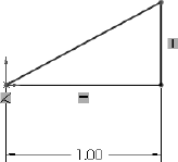
Draw a line horizontal from the Origin. Remember that there are two ways to sketch the line, Click-Click or Click-Drag. Make sure that the line snaps to the horizontal and that there is a yellow Horizontal relation symbol. The PropertyManager for the line should show that the line has a Horizontal relation. Also notice that the line is black, but the free endpoint is blue. This means that the line is fully defined except for its length. You can test this by dragging the blue endpoint.
Click the Smart Dimension tool on the Sketch toolbar, use it to click the line that you just drew, and place the dimension. If you are prompted for a dimension, type 1.000. If not, then double-click the dimension; the Modify dialog box will appear, enabling you to change the dimension.
Draw two more lines to create a right triangle to look like Figure 4.30. If the sketch relations symbols do not show in the display, turn them on by clicking View
Drag the blue endpoint of the triangle. Dragging endpoints is the most direct way to change the geometry. Dragging the line directly may also work, but this sometimes produces odd results, particularly in versions earlier than SolidWorks 2007. The sketch leaves a ghost when dragging so that you can see where you started.
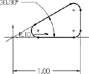
Click the Smart Dimension tool, and then click the horizontal line and the angled line. This produces an angle dimension. Place the angle dimension inside the triangle, and give it a value of 30°.
Click the Sketch Fillet tool, set the radius value to 0.10 inches, and click each of the three endpoints. Where the 1.000-inch dimension connects to the sketch, SolidWorks has created virtual sharps. Figure 4.31 shows the sketch at this point. You may now want to turn off the Sketch Relations display because the screen is getting pretty busy. You can find this setting at View
Draw a line starting from the midpoint of the angled line. The midpoint should highlight when you move the cursor close to it. Draw the line perpendicular to the angled line. A dotted gray line appears, showing where the perpendicular lies. When you follow this line, the yellow perpendicular symbol appears on the cursor. Make this line approximately .75 inches long. Feedback on the cursor also shows the length of the line as you draw it.
Draw two more lines ending at the endpoint of the sketch fillet, as shown in Figure 4.32. Use the Inferencing lines to line up the second angled line with the end of the arc. The last line drawn is thin, and the second line drawn is blue. The thin line indicates that there is a potential problem with the sketch, but not an error in solving the relations. The problem is that an extrude requires a single closed loop, and this sketch is not a closed loop.
Click the Trim tool from the Sketch toolbar. Make sure that the Trim option is set to Closest. Click the angled line of the triangle between the thin line and the line at the midpoint. This trims out that section, and makes the sketch a closed loop, so that the thin line now has a regular thickness. A warning may appear because you have a Midpoint relation to the line being trimmed, and you no longer want this relation, but you want the lines to intersect at their endpoints. Select Yes at the prompt.
Click the Smart Dimension tool. Use it to create aligned dimensions on the short line (.25 inches) and one of the long lines (.125 inches). You may now want to reorganize some of the dimensions if the display is becoming crowded.
At this point, two of the lines should be blue, but it may not be clear why they are not defined. Select one of the blue lines and drag it. Notice that what changes is the arc nearest the Origin. This changes in a way that is not useful for this part. To lock this line where it needs to be, select the blue line nearest the Origin and the centerpoint of the arc nearest the Origin, and give them a Coincident relation in the PropertyManager. The result is a fully defined sketch, as shown in Figure 4.33.
Save the part with the name Sketch Relations Tutorial.sldprt. Close the part.


Sometimes I am amazed at the things that can be done in SolidWorks, even with fairly simple tools. This is one of those times. If you design machines, then this tutorial will have some extra meaning for you. If you do not design machines, then these are still valuable tools to have in your toolbox ready to use in various situations. Follow these steps to learn about using Blocks and Belts.
Open a new part with inches as the units.
Draw a sketch on the Front plane as shown in Figure 4.34, with four lines connected to the Origin. Exit the sketch and rename it as Layout Sketch, either by clicking twice on the name of the feature in the FeatureManager or by selecting it and pressing F2.
Open a second sketch on the Front plane, and draw a circle centered on the Origin with a 6-inch diameter.
Inside the circle, draw a rectangle around the Origin.
Select two adjacent sides of the rectangle and make an Equal sketch relation between them (this makes the rectangle into a square).
Draw a diagonal construction line (using the Centerline tool) across the square from corner to corner.
Press Esc to exit the Centerline command.
Select the centerline, Ctrl-select the Origin, and apply a Midpoint relation to them. This is a very common technique for centering a rectangle on a point.
Note
The CD-ROM for Chapter 2 contains a macro that automatically draws a rectangle that is centered on the Origin.
Click the Smart Dimension tool, and apply a 1.000-inch dimension to one side of the square. Turn off the Smart Dimension tool by clicking it again on the toolbar or pressing Esc.
If the Blocks toolbar is not active, then activate it and select Make Block. You can also access this command through Tools
Window select the circle and the square by clicking and dragging a box that includes all of the items in the sketch. The PropertyManager to the left displays a circle and five lines that are to be made into a block.
Expand the Insertion Point panel in the PropertyManager. This causes a blue manipulator Origin to appear in the graphics window. Click this Origin and drag it onto the center of the circle. Then click the green check mark icon to exit the Make Block dialog box. This is shown in Figure 4.35.
The items in the block now turn gray. Click anywhere on the block and drag it out of the way. Then drag the center of the circle and drop it on the part Origin.
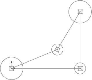
Click the Insert Block tool on the Blocks toolbar. Place the block on the opposite sharp corner of the layout sketch.
Create another block that is identical to the first one, except that it has a diameter of three inches instead of six inches. You can do this by selecting the first block, clicking Edit Block from the toolbar, and copying (window select and Ctrl+C). Then exit the Edit Block and paste (Ctrl+V) in the regular sketch. Make sure to also change the insertion point for this second block to the center of the circle.
Insert a second instance of this second block, and make sure that both of them have the center of the circle at the two remaining intersection points of the four-sided shape of the layout sketch. At this point, your sketch should look like Figure 4.36.
Click the Belt/Chain tool on the Blocks toolbar. Select the blocks in counter-clockwise order, starting at the Origin. On the last pulley, you will have to click the arrow to get the belt to go the correct way around the pulley.
Make sure that the Engage Belt option is selected. This allows you to make the pulleys move in the same way that they would in a real mechanism.
Click the Use Belt Thickness option, and assign .25 inches for the thickness. The belt should be offset from the pulleys.
Click the green check mark icon.
Click and drag one of the corners of the square in a pulley. All of the pulleys should turn as if this were a real mechanism. The ratios are also observed because the small pulleys rotate faster than the large ones.
Save this part as Blocks and Belts Tutorial.sldprt. Exit the part.


Sketching in SolidWorks is something that you will do almost every time you open the software. There are a lot of automated features available that you can allow to do the work for you. You also have a lot of control to make changes manually.
The options for creating intelligent relationships that establish your design intent, as well as SolidWorks' capabilities in laying out mechanisms, is only limited by your imagination. The more familiar you become with the tools in your toolbox, the more of a craftsman you can become with this software.