
IN THIS CHAPTER
Putting dimensions on drawings
Dimension options
Adding tolerances
Using dimension favorites
Tutorial: Working with dimensions and tolerances
In years past, dimensioning and tolerancing was an art form and a science. People did, and still do, become very passionate when discussing the right way of performing these tasks. In truth, the techniques are probably not so black and white, but are highly dependent on the industry, the means of manufacture, and the purpose of the drawing. For example, the drawing could be used for quotes, manufacturing, inspection, assembly, testing, and so on, and the drawings for each of these purposes would be somewhat different.
While it is important to follow standards and use manufacturing drawing conventions properly, this is not an argument that I want to reignite here. In this chapter, I will focus on how to apply the available tools in SolidWorks.
Drawings are typically not one of the hotter topics that SolidWorks users become excited about, but a few issues still ignite heated discussions. How to put dimensions onto drawings is one of these topics. This is much like the "tastes great/less filling" debate. Each side of the issue has valid points, and the question is not likely to be resolved any time soon.
At the center of this debate is whether the dimensions that you use to create the model should be placed directly on the drawing, or whether a dimensioning scheme specifically for the drawing is better. In the following sections, each method is examined for its benefits and drawbacks.
You can insert the model items on a per-feature basis, either only bringing the items that are appropriate into the current view, or bringing items into all views. Insertion can be further broken down by type of item, and it can become as specific as pattern counts, Hole Wizard items, specific symbol types, and reference geometry types. You can select Insert,

Usually, the dimensions need to be rearranged, although SolidWorks does try to arrange them so that they do not overlap. Figure 23.2 shows the result of bringing dimensions into all views for the part. The part is on the CD-ROM in the Chapter 21 materials.
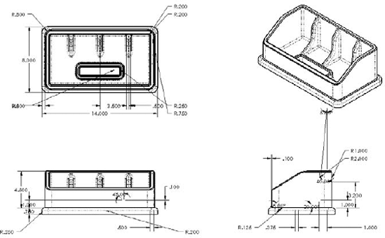
Figure 23.2 contains duplicate dimensions, overlapping dimensions, unnecessarily long leaders, radius dimensions pointing to the wrong side of the arc, and a lot of awkward placement. This is what you can expect from using the automatic functions. At best, these dimensions require rearranging, and at worst, they probably require that you delete and replace some of them, or move them to new views where they make more sense.
To move a dimension to another view, you can Shift-drag it from one view to the other (make sure that the dimension is appropriate in the destination view). To copy a dimension, you can Ctrl-drag it. If you cannot place the dimension in the view that you have dragged it to, then the cursor will indicate this with a special cursor symbol.
If you approach this task by placing dimensions on a per-feature or per-view basis, then that does not change the number of dimensions that you will have to move; it just means that they have to be inserted more often. Keep in mind that if you choose this method, there is a significant amount of cleanup and checking that you must do. The convenience of having the dimensions put into the views for you, and the ability to actually change the model from the drawing are quite useful, but you may not save very much time or effort by doing things this way.
The alternative to automatically inserting model dimensions is to manually place reference dimensions. At first, this appears to be simply recreating work that has already been done, and this is somewhat true.
However, in several important ways, these dimensions are not merely duplicates of the model items. In fact, the reference dimensions that you manually place on the drawing are quite different from the dimensions that are used in the model, unless either the dimensioning scheme of the model or the drawing is changed in some extreme way. The dimensions serve completely different purposes in the two settings, and could only be the same through some odd coincidence.
When modeling, I tend to dimension symmetrically, but only on one side, which would not be shown on a manufacturing or inspection drawing. I frequently use workarounds that force a different modeling-dimensioning scheme than I would prefer to use. Often, a feature is located from the midpoint of an edge, which involves no dimensions whatsoever. Sketch entities may have Equal relations, which also leave sketch elements undimensioned. Beyond that, when draft is involved, as is the case with plastic or cast parts, the dimensions of the sketch that you used to create the feature often have little to do with the geometry that is dimensioned on a print for inspection or mold building. Dimension schemes in models reflect the need for the model to react to change, while dimension schemes in drawings reflect the manufacturing or inspection methods, in order to minimize tolerance stack-up, and to reflect the usage of the actual part.
Although there are strictly technical reasons for dimensioning drawings independently from the way the model was dimensioned, there are other factors such as time, and the neat and orderly placement of dimensions. Time is an issue because by the time you finish rearranging dimensions that were inserted automatically from the model—checking and eliminating duplicates and then manually adding dimensions that were left out or that had to be eliminated because they were inappropriate for some reason, as well as ensuring that all of the necessary dimensions are on the drawing—it would have been much quicker to manually dimension the drawing correctly the first time using reference dimensions. Inevitably, manually inserting dimensions leads to a different scheme than would be imposed on you by using the Insert Model Items method.
It is my opinion that inserting model dimensions into the drawing is in most cases impractical for manufacturing or inspection drawings. This is because of the amount of time required to rearrange and check the dimensions, the need to ensure that you have placed the necessary dimensions, and the simple fact that the dimensioning and sketch relations needed for efficient modeling are usually very different from the dimensioning needed for manufacturing or inspection.
It is recommended that you use the manual dimension placement option, which works much in the same way as when dimensions are added to sketches. Dimensions that you place in the drawing in this way are called driven or reference dimensions. Technically, reference dimensions are "extra" dimensions that you place to ease calculations, and you usually create these dimensions with parentheses around them. You can find the setting that controls the parentheses around reference dimensions at Tools
Annotation views are views in the model in which annotations have been added. These are generally used by people who are using model dimensions on drawings. Annotation views are accessed from the Annotations folder in the model FeatureManager. They are created automatically when dimensions or notes are added to the part. The annotation view can be used in the model to show the note or dimension in the view in which it was created, or on the drawing to help parse the dimensions into views where they are easily read.
Annotation views can be inserted manually or automatically. You can access the settings for annotation views through the RMB menu of the Annotations folder, shown in Figure 23.3.

Driven dimensions on the drawing display in gray, and this can be a problem when the drawing is printed out. There are two methods that you can use to deal with this printing problem. The first method is to set the Page Properties of the drawing to force it to print in black and white. You can find the Page Properties at File
The second method is to set the color for driven dimensions to black rather than gray. This color setting is found at Tools

Baseline dimensions are normal linear dimensions that all come from the same reference, and are stacked together at a defined spacing. The default settings for baseline dimensions are found at Tools
Tip
Baseline dimensions work best either when they are horizontal or when the dimension text is aligned with the dimension line (as is the default situation with ISO standard dimensioning). Vertical dimensions where the text is horizontal do not usually stack as neatly because the dimension text runs over the dimension line of the adjacent dimensions.
Figure 23.5 shows ordinate and baseline dimensions in the same view.
You can access ordinate and baseline dimensions from the Dimensions/Relations toolbar (although they are not there by default, you must place them there with the Tools

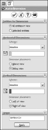
The Autodimension function can fully dimension the geometry in a drawing view. This is best for ordinate or baseline dimensioning where many dimensions are derived from a common reference, as is often the case with sheet metal parts or a plate with many holes drilled in it. You should limit the use of this option to cases where that type of dimensioning is what you would choose, having the choice of all available types of dimensions—do not allow the software to dictate the dimensioning scheme for your drawing.
Note
The Autodimension function is different from the Fully Define Sketch function, which is new in SolidWorks 2007. Autodimension works in the drawing, only adding dimensions. Fully Define Sketch works in the model sketch mode, adding dimensions and sketch relations. In previous versions, these functions were consolidated in a single function called Autodimension.
For some types of dimensions, you may need to create additional reference sketch entities. For example, with angle dimensions, it may be desirable to add construction lines to help define the angle. You can add centerlines as separate axis-like entities, as discussed in Chapter 22, but you can also sketch in centerlines manually if needed. This type of sketch is most often attached to the view rather than the drawing sheet.
Tip
Remember that, if necessary, you can create angle dimensions by selecting three points (vertex of the angle first) instead of two lines. When you do this, sketch lines are typically drawn to indicate the vertex of the angle.
The Dimension PropertyManager contains settings, default overrides, tolerances, favorites, and several other important settings for use with dimensions. The PropertyManager for driven dimensions is shown in Figure 23.7. Favorites and tolerances are covered in their own sections later in this chapter, but the other panels of the Dimension PropertyManager are described in the following paragraphs.

The Dimension Text panel enables you to add text to the dimension. You can add lines of text both before and after the dimension value itself, and you can also add text before and after the DIM value on the same line. The DIM field is what places the actual value; if this syntax is somehow deleted, then you can just type it back in and the dimension will still work.
The Dimension Text panel includes some formatting tools, such as justification and a setting for the position of the dimension line. The last two rows of buttons include the more commonly used symbols, with access to the complete library, such as any custom symbols that you may have made for the library.
Among SolidWorks users, one of the biggest and most common mistakes made by former AutoCAD users is the override of dimension values. Apparently due to popular demand, the Primary Value Override is now available in SolidWorks 2007 drawings, in the Dimension PropertyManager as shown in Figure 23.7. This option was added to the software mainly to enable the creation of dimensions with words instead of numbers, as shown in Figure 23.8.

You can control the default setting for parentheses around driven, or reference, dimensions in Tools
Although you can also control dual dimension defaults in Tools
Note
If it has been a few releases since you examined the Dual Dimension options, then you may find that SolidWorks 2007 has improved placement options for the dual dimensions.
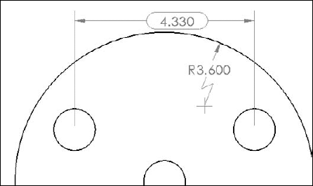
The foreshortened radius is only valid for individual radial dimensions. A foreshortened radius is shown in Figure 23.9. Foreshortened radius dimensions are typically used for large radii when dimensions to the center point are not important.
The inspection dimension is shown in Figure 23.9 with an oval around the dimension.
This panel enables you to set the arrows and dimension lines to be placed inside the witness lines. You can perform this function more easily by using the handles on the arrowheads. From this panel, you can also change the display type of individual arrowheads.
When you select the Use Document Gap option in this panel, the witness, or extension, lines of the selected dimension are broken by other crossing dimension lines, witness lines, or arrows. This is shown in Figure 23.10.
Layers are discussed in detail in Chapter 25.
The More Properties button displays the older Dimension Properties dialog box, which has some duplicate settings, but also contains some less commonly used options that are only available through this interface. Examples of these settings include units, dimension font, control over individual arrow style, and the ability to turn arrows and extension lines on or off. The remaining settings are duplicates of settings in the PropertyManager interface. The Dimension Properties dialog box is shown in Figure 23.11.


You can add dimension tolerances in the Dimension PropertyManager, which you can activate by selecting the dimension that you want to modify. Available tolerance types include:
Basic
Bilateral
Limit
Symmetric
MIN
MAX
Fit
Fit with tolerance
Fit (tolerance only)
Note
You can also add tolerances to dimensions in models; the tolerance is brought in with the dimension if you use the Insert Model Items feature.
The Tolerance/Precision panel is shown in Figure 23.7. The appropriate number entry fields are activated when you assign the corresponding tolerance type to the dimension. The tolerance types that are available in SolidWorks are shown in Figure 23.12.

In SolidWorks, precision means the number of decimal places with which dimensions are displayed. Typically, SolidWorks works to eight places with meters as the default units. You can create templates that use up to that number of places as the default setting, and then change the number of places for individual dimensions as necessary. The first of the two boxes under Precision is used for the dimension precision, and the second is used for tolerance precision.
You can change Precision values for individual dimensions in the PropertyManager for the dimension, and for the entire document at Tools
You can use dimension favorites to apply many items to dimensions. Unlike notes, this is not limited to fonts and formatting. Some of the most common uses of dimension favorites are:
You can save favorites from one document and load them into another document, even between document types. For example, you can load part dimension favorites into a drawing.
When an external favorite is updated, any document that it is linked to also updates. In addition, you can break links to external favorites (with the appropriate button on the Favorites panel). Otherwise, dimension favorites have very similar functions to the other types of favorites; the functions of all of the buttons on the Favorites panel are the same.
In this tutorial, you can use a single part in several different ways to demonstrate different dimensioning and tolerance functions. Follow these steps to learn more about these topics:
Open the part from the CD-ROM called Chapter 23 Tutorial.sldprt.
Open the drawing from the CD-ROM called Chapter 23 Drawing.slddrw.
Tile the windows using Window

Delete the Top view, leaving the views as shown in Figure 23.14.
Click Insert
The resulting drawing is quite cluttered. Delete and move dimensions so that the drawing looks like Figure 23.15.
Shift-drag the surface finish symbol to the Right view, and do the same with the 1.900-inch dimension. You may have to first Shift-drag it into the other view, and then drag it again to correctly attach or position it.
Create a set of horizontal ordinate dimensions from the left end of the part, and dimension the X position of each column of holes. Do the same for rows of holes, using the bottom edge of the Front view as the zero reference. Remember that you can create ordinate dimensions by starting a normal Smart Dimension, then RMB clicking to display the More Dimensions list, and then selecting your choice.
If necessary, add center marks and centerlines to the view for clarity.
Select the .188 diameter dimension, and in the Dimension Text box, type TYP after the <DIM> text, and add a bilateral tolerance of +.003, -.005. Save this as a favorite by clicking the Add Favorite icon.
Apply the newly created dimension favorite to the R.100 dimension. The results up to this step are shown in Figure 23.16.
Make one of the dimension leaders for either the .188 or the R.100 dimensions cross the extension lines of the 4.500 dimension. Then select the 4.500 dimension and in its PropertyManager, select the Use Document Gap option in the Break Lines panel.
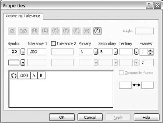
Place a B datum marker on the circumference of the smaller arc on the left end of the part. Create a Geometric Tolerance control frame, as shown in Figure 23.17.


The argument about how to set up and use dimensions on drawings is as old as the process of creating geometrical plans from which objects are built. It is often difficult to separate fact and best practice from opinion. Although I leave it up to you to decide these issues for yourself, this chapter is intended to help you understand how to create the type of drawing that you want.
The biggest conflict in this subject arises over whether to place live model dimensions on the drawing or to allow the requirements of the drawing to specify which dimensions are placed where. I am by no means impartial when it comes to this question, but again, you must make the choice for yourself.