
IN THIS CHAPTER
Architecture of Insert Bends
Making sheet metal from a generic model
Working with imported geometry
Making rolled conical parts
Mixing methods
Tutorial: Working with the Insert Bends method
In Chapter 29 on the Base Flange method, I explained the co-existence of two conceptual models for the creation of sheet metal parts in SolidWorks. The Base Flange method is the newer and more powerful of these two functions. However, some functionality is available only through the Insert Bends method, and the two methods may be combined to some extent. This shows that the older method is by no means obsolete.
One of the reasons for creating a new method was that the old method was very convoluted, and required certain types of features to be put into specific locations in the FeatureManager order; this meant that the user was frequently working in Rollback mode. In the days before being able to save in Rollback mode (which is new in SolidWorks 2007), this was not only tedious but dangerous, as well. This is because without the ability to save while the model was rolled back, users were more likely to lose their work.
One of the advantages of the old method was that you were able to just use the same old SolidWorks features that you were accustomed to using for regular modeling. Of course, this same advantage frequently turned out to be a disadvantage, as well because the standard features by definition did not have any specialized sheet metal functionality.
Today, the Insert Bends method is used for specific situations. For example, it is used for parts that have been created as generic SolidWorks models and that need to be flattened, imported parts that need to be flattened, and conical rolled sheet metal parts.
In Chapter 29, it was shown that a part created with the Base Flange method had as its first feature a Sheet Metal feature, which was a placeholder for sheet metal defaults for the current part. The Base Flange feature came next, followed by additional Sheet Metal features, and the list of specialized features was completed with a suppressed Flat Pattern feature.
The structure of parts created with the Insert Bends feature is somewhat different. Figure 30.1 shows a comparison of the two methods' FeatureManagers for simple parts.

The most notable difference is that the Insert Bends part starts off with non-sheet metal features. The Rip feature also stands out, but the Rip feature is not exclusive to sheet metal. Although you can use Rip on any model, it is found only on the Sheet Metal toolbar.
The Sheet Metal feature is found in both the Base Flange and Insert Bends methods, and has the same PropertyManager function in both methods.
The new features in the Insert Bends method are the Flatten Bends and Process Bends features. The way the Insert Bends method works is that the model that is built with the sharp-cornered non-sheet metal feature is flattened by the Flatten Bends feature. The model is then reconstructed with bends by the Process Bends feature.
In earlier versions of SolidWorks, the Flat Pattern did not exist, and so to create a flat of your model, you suppressed the Process Bends feature. This is where the implications of the feature order became apparent. To build a cut across a bend (which you can do with the Unfold and Fold features in Base Flange parts), the cut had to be put between the Flatten and Process Bends features. Changes to the overall shape, and especially new bend geometry, had to be added before the Flatten Bends feature. Features could also be added after the Process Bends, but they would not appear on the flat pattern; this was reserved for secondary machining operations, and other features of that type.
With this brief explanation of the feature-order sensitivity of the Insert Bends method, you begin to get a sense of why a new architecture was created.
At least two basic rules are enforced by SolidWorks for all sheet metal parts: the parts must have a constant wall thickness, and the thickness faces must be perpendicular to the face of the part (edges are not sheared at a non-perpendicular angle). When all of the geometry is made from the beginning as a sheet metal part (using the Base Flange method), these issues rarely arise. However, when the part is modeled from thin features, cuts, shells, and so on, there is no telling what may happen to the model.
If you perform an Insert Bends operation on a model that does not have a consistent wall thickness, then the Flatten and Process Bends features fail. If a thickness face is not perpendicular to the main face of the part, then the software simply forces the situation.
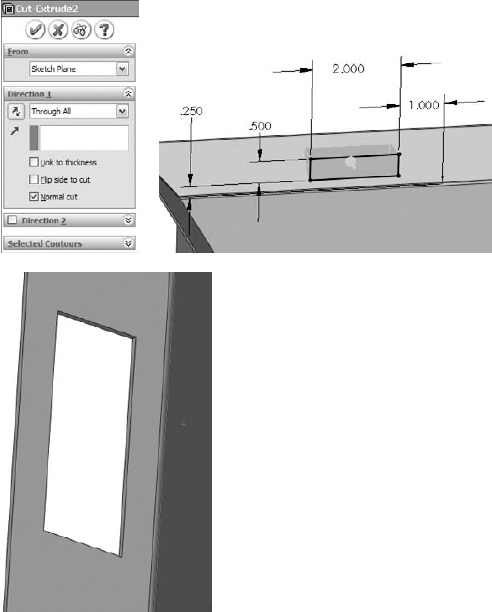
If a Cut feature is placed before the Sheet Metal feature, then as far as SolidWorks is concerned, the part is not a sheet metal part. However, if the cut feature is created after the Sheet Metal feature, then the model has to follow a different set of rules. The "normal shear" mentioned above is one of those rules. In Figure 30.2, the sketch for a cut is on a plane that is not perpendicular to the face that the cut is going into. Under a normal modeling situation, the cut just goes through the part at an angle. However, in SolidWorks sheet metal, a new option is added to the PropertyManager for the cut. This is the Normal Cut option, and it is turned on by default. You could be modeling and never even notice this option, but it is important because it affects the geometrical results of the feature.
As shown in Figure 30.2, when the Normal Cut option is on, the thickness faces of the cut are turned perpendicular (or normal) to the face of the sheet metal. This is also important because if the angle between the angled face and the sketch change, the geometry of the cutout can also change. This setting becomes more important as the material becomes thicker and as the angle between the sketch and the sheet metal face becomes shallower.

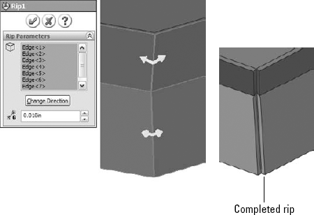
Figure 30.3 shows the Rip PropertyManager and the results of using this feature. The model was created to look like a Miter Flange part.

Notice also in Figure 30.3 that after the Rip, the edges of the material are still sheared at an angle. Because the top of the part was shelled, the thickness of the part is not normal to the main face of the sheet metal. You can fix this by using the Flatten Bends feature, which lays the entire part out flat, calculates the bend areas, and corrects any discrepancies at the edges of the part.
Note
Rip functionality is included in the Insert Bends Sheet Metal PropertyManager when it is first initiated, although it is no longer there when you edit the part later. If it is used, the Rip data becomes a feature of its own and is placed before the Sheet Metal feature in the FeatureManager. Be aware that there are slight differences between using the Rip function as an independent feature and using it as a part of the Insert Bends feature. You may want to check this on a part you are working with to verify which method best suits your needs.
The Flatten Bends feature is added automatically by the Insert Bends tool. As mentioned earlier, it takes the model with sharp corners and lays it flat, adjusting the material in the bend area and normalizing the thickness faces around the flat pattern. A Merge Faces option is not available in the Insert Bends method except in the Flat Pattern feature, and so the flat pattern created by the Flatten Bends feature always has edges created by the tangent lines of the bends.
Notice in Figure 30.4 that the Flatten Bends feature has a sketch and several Sharp Bend features under it. The Sharp Sketch is simply an account of the bend lines, and you cannot edit it manually. The Sharp Bend features can be suppressed, in which case they are not re-formed in the Process Bends feature. You can also edit Sharp Bend features to change the default radius, bend allowance, and relief type.

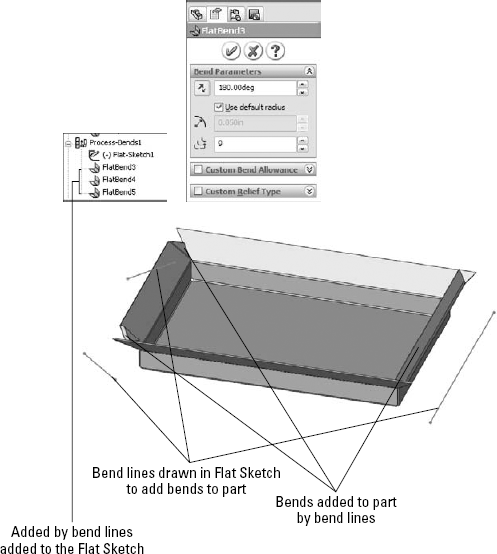
The Process Bends feature takes all of the flat pattern information, the bend information, and entities in the Flat Sketch, and rebuilds the model with the formed bends. The Flat Sketch under the Process Bends feature is the Insert Bends method version of a sketched bend. You can add sketch lines here to bend panels of the part. After you add lines to this sketch, exiting the sketch causes the part to be created with a default 90-degree bend corresponding to the line. Of course, all of the Sketched Bend rules exist, such as that the line has to extend at least up to the edges of the part, the lines cannot extend across multiple faces, and construction lines are ignored.
For every bend created by a sketch line in the Process Bends Flat Sketch, a Flat Bend feature is added to the list under Process Bends. You can control the angle and radius of each of these Flat Bends by editing the Flat Bend feature. This is all illustrated in Figure 30.5.
Working with imported geometry starts at the point where you use the Rip feature. While imported geometry can be geometrically manipulated to some extent in SolidWorks, that is beyond the scope of this chapter. The need for a model with walls of constant thickness still exists, even if the imported model has filleted edges showing bend geometry already in the model.
FeatureWorks may be used to recognize sheet metal features or to fully or partially deconstruct the model by removing bend faces as fillets. While FeatureWorks is not covered in this book, the technique may be useful when editing imported parts with overall prismatic geometry that is common to sheet metal parts.
When a sheet metal part is imported, whether it meets the requirements immediately or must be edited in one way or another, to make a sheet metal part of it, you can simply use the Insert Bends feature.
One of the reasons for maintaining the legacy Insert Bends method is to have a way of creating rolled conical parts. You can create cylindrical sheet metal parts by drawing an arc that almost closes to an entire circle, and creating a Base Flange from it. However, no equivalent technique for creating tapered cones exists with the Base Flange method.
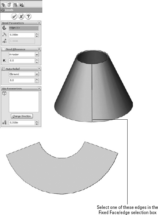
With the Insert Bends method, a revolved thin feature does the job nicely. You simply revolve a straight line at an angle to the centerline, so that the straight line does not touch or cross the centerline; the revolve cannot go around the full 360 degrees, as there must be a gap. Sheet metal parts are not created by stretching the material (except for Forming Tools).
When creating a rolled sheet metal part, a flat face cannot be selected to remain fixed when the part is flattened. Instead, you can use a straight edge along the revolve gap, as shown in Figure 30.6.
Note
When a conical sheet metal part is created, it does not receive the Flat Pattern feature at the end of the FeatureManager. This is because none of the new Base Flange method features are allowed on this type of part.
Once you have used the Insert Bend tool on a part, it is not automatically excluded from using some of the more advanced tools that are available through the Base Flange method, unless it is a cylindrical or conical part. A Flat Pattern feature is added to the bottom of most feature trees, and the presence of this feature is what signifies that the current part has now become a sheet metal part to the Base Flange features.
However, it is recommended that you avoid mixing the different techniques to flatten parts, for example, suppressing bends under Flatten and Process Bends, as well as using the Flat Pattern.
The Insert Bends method has been relegated mainly to duty for specialty functions. Gain an understanding of how this method works by following these steps:
Create a new blank part.
On the Top plane, open a sketch and sketch a rectangle centered on the Origin 12 inches in the Horizontal direction and 8 inches in the Vertical direction.
Extrude the rectangle 1 inch with 45 degrees of draft, Draft Outward, in Direction 1, and in Direction 2 extrude 2 inches with no draft. The two directions should be opposite from one another.
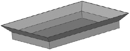
Shell out the part to .050 inches, selecting the large face on the side where the draft has been applied. The part should now look like Figure 30.7.
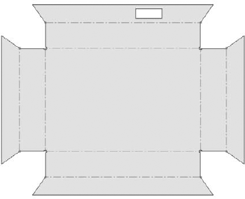
Use the Rip feature to rip out the four corners. Allow the Rip to rip all corners in both directions. The part should now look like Figure 30.8.
Draw a rectangle on one of the vertical faces of the part, as shown in Figure 30.9.
Use the sketch to create a Through All cut in one direction. Notice that the Normal Cut option is on by default. Examine the finished cut closely; notice that it is different from the default type of cut because it is not made in a direction normal to the sketch, but rather in a direction normal to the face of the part. Details of this are shown in Figure 30.10.
Click the Flatten button on the Sheet Metal toolbar. Notice that the Flat Pattern feature becomes unsuppressed and that the Bend Lines sketch under it is shown. This works just like it did in the Base Flange method. The finished part is shown in Figure 30.11.

The Insert Bends method was convoluted, requiring a lot of jumping around between rollback states, and reordering to place features in the proper order so that everything appears on the flat pattern where it belongs. The new tools are far easier to use, but do not replace all of the functionality of the old technique.