
IN THIS CHAPTER
Understanding in-context design
Dealing with practical details of in-context modeling
Other types of external references
Tutorial: Working in-context
In-context modeling offers a gateway to a world of expanded modeling possibilities in SolidWorks. The topic of in-context modeling is often a source of sometimes questionable advice and suggestions from even experienced users. In this chapter, I offer a balanced explanation with each suggestion so that you can evaluate the suggestion for yourself.
If you are well disciplined in your modeling practices, and understand the potential problems of in-context modeling, then you can avoid these problems. After one bad experience, some users focus on this experience, and fail to see the positive side of using in-context modeling. Although dangers do exist, they often result from disregarding the rules.
In-context modeling is also known as top-down modeling. It is a technique that is used to create relationships between two parts in an assembly, where the geometry of one of the parts is controlled by both the other part and the mates that position them relative to one another.
In-context, or top-down, modeling may be contrasted against bottom-up modeling. Bottom-up modeling involves making the parts in their own individual windows and assembling the finished parts into an assembly with mates.
In its most common form, a sketch in one part in an assembly is related to another part in the assembly. The relationship is specific to that particular assembly, and is only relevant in the context of that assembly. For example, you may create a box and put it into an assembly. You must then create a lid that is parametrically linked to the size and shape of the box. You can create a lid part in the context of the assembly such that the lid always matches the box. Sketch relationships, dimensions, and feature end conditions from the lid can reference the box. When the box changes, the lid also changes if the assembly is open.
The assembly maintains a record of the reference. If the box is changed with both the assembly and the top open, then the top updates, but if the box is changed without the assembly being open, then the lid will not update until the assembly is opened. The record of the reference that the assembly maintains is held in what is called an update holder, and in recent versions, it is all but forgotten.
Note
Chapter 12 discusses in-context reference update holders. These are the pointers in the assembly that hold the reference information. These holders are hidden by default, and do not enable any real functionality, but they do serve as a reminder that the assembly has in-context references, and can be queried to tell you what parts the in-context relations go between.
The advantages of in-context modeling are obvious. I spent the first couple of chapters of this book discussing the strengths of parametric design, and in-context modeling is just an extension of parametric techniques to include parts in the context of an assembly. Making a change to one part and having all related parts update offers indisputable advantages.
There may also be some issues that arise from this technique of driving changes from a different part model. There are no problems with the overall concept of in-context modeling; the problems occur with the practical application of the technique. In particular, the biggest problems seem to arise when in-context techniques are combined with other techniques. You must be very careful about file management issues when in-context references exist in your assembly.
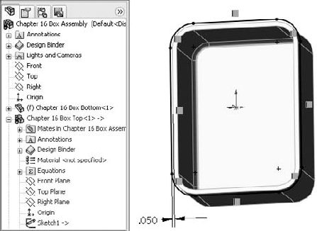
Figure 16.1 shows a simple box with the sketch of a simple top for the box. Notice in the FeatureManager that two parts are listed as the Box Top and Box Bottom. The .050-inch offset is creating a sketch in the Top part that is driven by the edges of the Bottom part. This simple assembly demonstrates the in-context process in the sections that follow.
You can perform in-context modeling using one of two basic schemes. You can build parts from the very beginning in the context of the assembly (using the Insert
To create the new part, click Insert
The mate that you are adding is called an InPlace mate. This works like the Fixed option, but is actually a mate that is listed with the other mates and that may be deleted, but not edited.
The InPlace mate clamps the part down to any face or plane where it is applied. It is meant to prevent the in-context part from moving. I will explain later in this chapter why it is so important for in-context parts not to move. Although the InPlace mate clamps the part down, I have heard people report bizarre behaviors with the InPlace mate reportedly allowing parts to move unpredictably, but I do not put any stock in these reports. The cause of things such as this usually turns out to be a user who is not paying attention to what is going on.
Note
Software is a very deterministic system, where everything happens for a reason. However, if a face on which an InPlace mate has been created is moved by the part changing, then the in-context part could possibly move in a way that you might not predict. The problem is that while the Front plane of the in-context part is defined with respect to the selected face, it is not explicitly defined rotationally about an axis perpendicular to the face, or translationally about axes parallel to the face.
If you are concerned about using the InPlace mate, then I would suggest an alternative technique. Instead of using the Insert
Sketches, edges, and faces from the other parts in the assembly can be referenced from the in-context part as if they were in the same part as the sketch. Most common relations are concentric for holes, and coincident for hole centers. Converted entities (On-Edge relations) make a line-on-edge relation between the parts, and Offset sketch relations are also often used.
Other types of valid in-context relations include in-context sketch planes, and end conditions for extrude features such as Up to Face and Up to Body. Beyond that, you can copy surfaces from one part using the Knit Surface feature, or the Offset Surface feature. I discuss surfacing in more detail in Chapter 27.
When working in-context or using in-context data, visual cues offer information about the part that you are working on. The following topics are all meant to help you understand what is going on.
When modeling in-context, the FeatureManager text of the part that you are working on turns blue. This should make it immediately obvious first that you are working in-context, and second, which part is being edited.
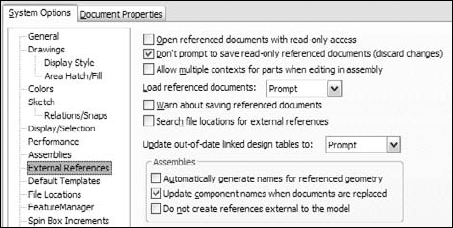
Color and transparency behavior of parts in the assembly where a part is being edited in-context can be controlled through the Tools

An additional setting in Tools

The options in the Assembly Transparency drop-down list are:
Opaque Assembly: All parts that are not being edited when an assembly component is being edited in-context will turn opaque, even if they are otherwise transparent.
Maintain Assembly Transparency: Leaves all assembly components in their default transparency state.
Force Assembly Transparency: Forces all of the parts, except for the one being edited in the assembly, to become transparent.
These options reflect personal preference more than anything else, but it is useful to have a reminder as to whether a part is being edited in the assembly or the assembly document is being edited in its own window.
Tip
The color selected in the box shown in Figure 16.2 controls both the text color and the color of the part shown in the graphics window.
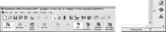
The second use of the Edit Component button is to begin or finish editing a part that is already in an assembly. When you are editing a part in the context of an assembly, the title bar of the SolidWorks window reflects the fact that you are editing a part in an assembly, the toolbar changes to a part-editing toolbar, and the lower-right corner of the taskbar displays the words Editing Part, as shown in Figure 16.4.
Editing a component can also mean editing a subassembly in the context of the top-level assembly. You can create in-context assembly features and mates if necessary. This is done far less frequently than editing parts in-context.
Note
Creating in-context relations is not the only reason to edit a part or subassembly in the context of the top-level assembly. Sometimes it is simply more convenient to do normal editing when you are in the top-level assembly, so that you can see how the part relates to other parts after making changes in the assembly without making relations between the parts.
Editing a subassembly in the context of the upper-level assembly is often useful as well, to see how changing subassembly mates affects the top level.
Probably the most common mistake that users make around the issue of editing the part versus editing the assembly is when they add a sketch. If you intend to add a sketched feature to a part in the context of an assembly, but you fail to switch to Edit Part mode before creating the sketch, then the sketch ends up in the assembly rather than the part; you can only do limited things with a sketch in an assembly. Likewise, if you intend to make an assembly layout sketch, but you do not switch out of Edit Part mode, then you end up with a sketch in a part that cannot do what you want it to do.
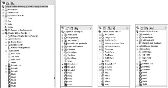
The external reference symbol appears as a dash followed by a greater-than sign. External references do not only indicate in-context features. You can also create external references by using the Split Part command as well as the Insert Part (base or derived part) or the mirrored part functions. Figure 16.5 shows the expanded FeatureManager for a part with an in-context reference in a sketch.
External references can have four states, which are also shown in Figure 16.5. These are:
In-context
Out-of-context
Locked reference
Broken reference
Out-of-context means that the document—usually but not necessarily an assembly—where the reference was created is not open at the time. It is indicated by an in-context symbol followed by a question mark. You can open the document where the reference was created through the RMB menu, using the Edit In Context option. Edit In Context opens either the parent part of an inserted part, or the assembly where the reference was created. When you open the referencing document, the out-of-context symbol changes to the in-context symbol.
You can lock external references so that the model does not change. Other features of the part may be changed, but any external reference within the part remains the way it is until the reference is either unlocked or removed. In our Box-and-Top example mentioned earlier, this means that if the Bottom part is changed, and the external reference on the Top is locked, then the Top will no longer fit the Bottom.
One of the best things about locked references is that you can unlock them. They are also flexible and give you control over when updates take place to parts with locked references.
The broken reference is another source of controversy. Some users believe that if you make in-context references, the best way to respond to them is to break them immediately. However, I would argue that using the Break References function is never a good thing to do. I believe that you should remove the reference by editing the feature or the sketch or change it to make it useful.
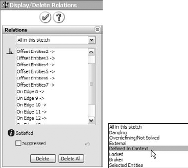
The problem with a broken reference is that it has absolutely no advantage over a locked reference. For example, while locked references can at least be unlocked, broken references cannot be repaired. The only thing that you can do with a broken reference is to use Display/Delete Relations or to manually edit features to completely remove the external reference. Perhaps it would be better for SolidWorks to replace Break References with a function called Remove References. Would anyone like to make an enhancement request?
Note
Best practice is to not put yourself in a situation where you are using either locked or broken references. Parametric relations should not change if the driving geometry does not change. Again, as is typical with CAD software, things may happen that you cannot explain, but there is always a reason for it (even if it is not immediately apparent).
You cannot selectively lock or break external relations. For example, all of the external relations in the part can be locked, all of the external relations can be broken, or none of them can be locked or broken. If you need to selectively disable relations, then you should consider suppressing features, sketch relations, end conditions, or sketch planes.
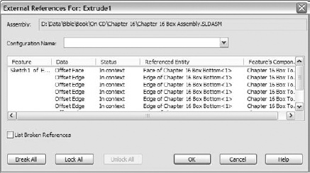
You can access the locked and broken references through the List External References option on the RMB menu of any feature with an external reference symbol. Figure 16.6 shows the name and path of the assembly where the external reference was created, as well as the part names and entity types.
This lack of references includes the InPlace mate, which is not created when a part is created in-context. As a result, when you add the part to the assembly, if you exit and later re-enter Edit Part mode, then SolidWorks reminds you that the part is not fixed in space by displaying the warning shown in Figure 16.7.

Figure 16.7. The dialog box that warns you about adding in-context relations to an under-defined part
This message should remind you that in-context features should be used only on parts that are fully positioned in the assembly.
In-context techniques are most frequently misused by beginning to intermediate users. Many users purchase the software because of the promise of parametric relationships between parts. However, this is a technique that requires a fair amount of discipline, restraint, and judgment.
The potential problems associated with overuse or misuse of in-context techniques primarily include performance problems (speed) and lost references due to file management issues. Users may also experience problems with features or sketches that change with each rebuild. The following section contains best practice suggestions that can help you avoid these situations.
Multiple contexts occur when a part has references that are created in multiple assemblies. By default, multiple contexts are prevented from happening. If you place a part that already has external references into a different assembly, a warning appears, as shown in Figure 16.9.
Although SolidWorks displays many warnings about multiple contexts, you may still run into situations where you need to use them. For example, you may have a subassembly where a part, such as a top plate of a stand, has in-context references to locate a set of mounting holes. When you place the subassembly into the top-level assembly and mount another assembly to the top plate, another set of in-context holes is required in the top plate.
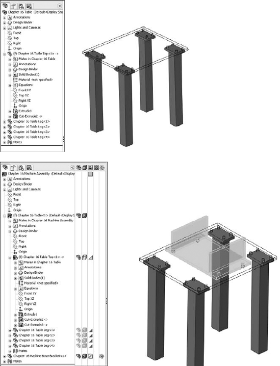
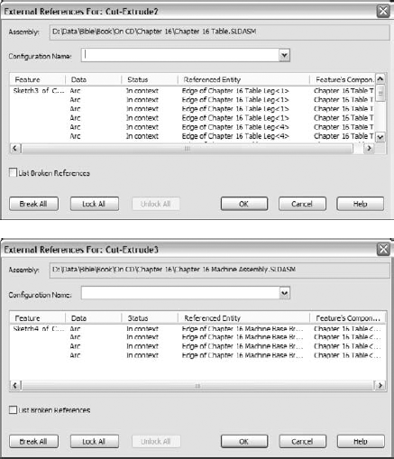
Figure 16.10, at the top, shows the first table and points out the in-context relations. At the bottom, the large bracket appears for the other machine that is mounted to the table top using more in-context relations. In Figure 16.11 are the External References dialog boxes for the two different in-context features. Notice that the Assembly fields at the top of the External References dialog boxes are different. You can only achieve this by activating the Allow Multiple Contexts for Parts When Editing in Assembly option shown in Figure 16.8.
Note
The Tools
Note
The best practice is to avoid creating multiple-context references. If you need to do this, then be very careful about naming files, and remember to turn off the multiple-context option when you have finished creating the reference.
If you receive a multiple-context part from someone else, the best thing to do is to determine whether you have all of the files required to make it work. RMB click the external reference symbol and select Edit In Context to determine whether SolidWorks can find the right files.
Aside from doing some programming, the only way to find out whether a part was created as a multiple-context part is to examine the External References list for each in-context feature. This can be very time-consuming. Although multiple-context parts should be very rare, it is impossible to determine ahead of time whether or not a part that you have received is a multiple-context part, at least without programming.
I once worked on a part that had both some in-context and some out-of-context features. Of course, this looks strange when you realize what you are looking at because in most situations, if any references are out-of-context, all references will be out of context. After some examination, I discovered that there were multiple contexts, which were created because of poor file management. The assembly had changed names slightly, and caused the original in-context relations to not be recognized. I will discuss in-context relations and file naming later in this chapter.
On the surface, mixing in-context references with configurations sounds like it is combining two powerful techniques that should offer you great control over models. Although this may sometimes be true, I want to caution you about some of the effects that combining these two techniques may cause. In particular, you should be careful about part configurations, particularly configurations of the referenced part.
If you are using in-context relations to parts with configurations, then you may want to consider a few things. First, look at the door-hinge part shown in Figure 16.12. At the top are three configurations of one of the hinge plates. The second hinge plate is built in the context of the assembly so that it will always match the first plate. At the bottom are the results of changing the first hinge-plate part configuration in the assembly. This looks like an ideal situation because the second hinge plate always changes to match the first hinge plate. What could be wrong with this?
The problem here is that you can only show the size of the second hinge plate that corresponds to the configuration of the first plate that is active in the assembly. If you had two instances of the hinge assembly in a top-level assembly, then you would be able to show only one size for the second plate.
A second situation where combining in-context references and configurations can cause you trouble is if you have referenced the edges of a part from another part, and a configuration of the referenced part either adds or removes fillets or chamfers, thus breaking the edges. Either of these situations can cause the in-context sketches or other features to fail. This may be a reason to reference the underlying sketches, rather than the model edges or faces themselves.
In some situations, configurations work well with in-context relations. One example of this would be when an assembly has many configurations used for positioning parts. Use one configuration for the sole purpose of creating in-context relations.
You should make in-context references between parts where there is no relative motion. The parts themselves can move relative to the rest of the assembly, but they should remain stationary relative to one another. The parts should also be fully defined to ensure that they will not move; you should not simply count on avoiding dragging underdefined parts.
In some cases, such as an assembly of imported parts, it may make sense to fix parts in bulk rather than to mate them. When you are using in-context relations, you need to take extra care to ensure that the parts do not move around. When parts move around, in-context features also move.
Obviously, if the motion is around a hole, and the in-context feature is circular and is not affected by the rotation of the referenced part, then it makes less difference; however, if there is a keyway, that may change things. You need to pay attention when combining underdefined parts and in-context features.
Note
For best practice, you should avoid in-context relations between parts when relative motion is allowed between these parts.
Another situation that can cause problems is when multiple instances of an in-context part are being used in the assembly. In cases like this, you need to be careful and consistent, by always using the same instance to create the in-context relations. You can do this by putting parts into folders, or giving the in-context part a special component color.
Understanding what you are doing with file management is imperative when working with parts that depend on in-context features. Because the references are stored in both the part that is doing the referencing and the assembly where the reference is created, improperly changing the name of either document is bound to cause problems. For example, if you rename an in-context part using Windows Explorer, then the assembly will not recognize the part, as demonstrated in an earlier chapter. This also means that any in-context references will not update.
Note
For best practice, you should use either the SolidWorks Save As command or SolidWorks Explorer to rename parts and assemblies.
This was mentioned earlier, but a section on in-context best practices would not be complete without issuing the warning against mating to in-context features. Mating parts to in-context features creates a parametric daisy chain, thus establishing an order in which assembly features and mates must be solved. This always creates performance problems in assemblies, especially large ones.
Circular references in assemblies are a bigger problem than most people realize. In fact, most people do not realize that circular references are a problem, or, for that matter, that they even exist.
A circular reference takes the form of "Part A references Part B, which references Part A." It creates a circular loop that really wrecks assembly rebuild times. Part feature design trees are not susceptible to this sort of looping because the part FeatureManager operates in a linear fashion (at least when it comes to applying relations between sketches or features).
The Assembly FeatureManager is solved in this order, or an order that is very similar:
Solve reference geometry and sketches that are listed before parts in order, at the top of the design tree.
Rebuild individual parts as necessary.
Solve the mates and locate the parts.
Solve in-context features in parts.
Solve reference geometry and sketches listed after the mates.
Solve assembly features and component patterns.
Loop to step 3 to solve mates that are connected to anything that was solved after the first round on the mates.
Continue to loop until complete.
As you can see, even if you do not have a reference such as "Part A references Part B, which references Part A," it is still possible to get a highly convoluted, if not entirely circular, loop. Many users with smaller assemblies in the hundreds of parts complain about very poor performance. Unfortunately, it is far easier to complain than to really examine what is going on.
When making in-context references, a technique that can help you avoid circular references is to always create references to parts that are higher in the design tree. You can expand on this idea until a single entity is at the top of the design tree, to which all in-context references are made. This could take the form of an Assembly Layout Sketch, or a skeleton. These concepts are discussed in chapters 11, 12, and 13.
Remember that the layout sketch consists of a single or even multiple sketches that control the overall layout of the assembly, as well as all of the relationships between parts. When you refer all of the relations to a single entity that does not change with part configurations, or lose or gain filleted edges, the inter-part parametrics become much stronger and more stable.
When building a mold for plastic injection molding, a single sketch can control the size and position of the plates, pins, and so on. If all of the 3D parts are mated to the 2D sketch, or use the 2D sketch by converted entities, then the parts will move with the sketch. This same technique is important and useful for any type of die or punch design, along with many other types of design.
Library parts should never contain in-context references, especially if the in-context references are out-of-context. Small library assemblies may have in-context references between the parts, but a single part should not have features created in-context. External references may be unavoidable in the form of mirrored or base parts, but in-context references are completely avoidable.
If you are considering using the Break Relations tool, then you should either reconsider and use Lock Relations instead, or simply remove all of the in-context relations altogether.
Other types of in-context references are not as easy to remove as sketch relations. When you see the External Reference symbol on a sketch, it could be the sketch relations, or it could be the sketch plane that was in-context. In order to fix this problem, you must redefine the plane locally in the part.
Tip
You can make a local plane from an existing in-context plane (or even just a 3D view) by using the following workaround. Looking normal to the view, open a 3D sketch, and draw three sketch points that do not pick up automatic sketch relations to anything else. Once the points are drawn, select all three of them and make them coincident. Then delete the coincident relation and drag the points apart. The three points come out on a plane that is parallel to the plane of the screen. Next, simply make a three-point plane.
You should also not forget end conditions such as Up To Surface, Offset From Surface, or even From Surface. If an external reference symbol remains on a feature, you can use the Parent/Child option on the RMB menu to locate it. Remember that using an edge or vertex for a plane definition can cause an in-context relation.
You should not become too enthusiastic about in-context relations. This can cause you to do things such as using in-context relations to locate parts, or using in-context instead of mating parts.
In-context modeling is like chocolate: a little is a wonderful thing, but too much can be bad for you. You should only use in-context to locate or size features. In-context is initially so fast and easy to use that it can be addictive, but you need to think before you use it.
If someone else needs to use your model after you are done with it and possibly edit it, then you should leave them some clues to help them understand how the model works, and how it is best changed. For example, you can use descriptive feature and sketch names, comments that are associated with features, the Design Binder to add documentation, and the Design Journal to write notes. You can even put HTML links in notes that display in the graphics window.
In-context design intent may not always be obvious, and an impatient user may find it more expedient to delete the in-context references and replace them with either local relations or no relations at all. The more you document your intent, the more likely others will be to follow it.
The external reference symbol (- >) indicates in-context features that have been created in the context of an assembly, but it also indicates three other types of external references:
Inserted parts
Split parts
Mirrored parts
Inserted parts are discussed to some extent in Chapter 10, and in more detail in Chapter 28. In the past, inserted parts have also been called base parts and derived parts, and some users still use those names.
An inserted part is simply an entire part that has been inserted into another part. This is sometimes referred to as a pull operation because the data is pulled from the original part into the child part. The part may be inserted at any point in the history of the design tree, and it may create an additional body within the part or be added to the existing one. Additional features can also be added to the inserted part, but you cannot see or change any of the features of the part that has been added from the downstream document. The inserted part becomes much like an imported, or dumb, solid.
Items that can be brought along with the inserted part are solid bodies, surface bodies, planes, and axes. You cannot bring features or sketches. You can use a particular configuration of the inserted part in the child part. I discuss this aspect in Chapter 14, dealing with configurations, and also in Chapter 28.
You can use inserted parts for many modeling applications, such as cast parts and secondary operations. You first insert the original cast part into a new blank part. Then, you add cut and hole features until the part resembles the finished part.
Another application for inserted parts is a single part that has been built from several models. For example, I once worked on a large, rather complicated plastic basket, where the basket was modeled as three individual parts, and then reassembled into a single part. Another application may be to insert a part as a body into a mold block to create a mold cavity. To insert a part into another part, you can select Insert, Part.
I discuss split parts in detail in Chapter 28, in the section about master models. Inserted and split parts are both master model techniques, as are a few more techniques that I discuss in Chapter 28. Some people also include in-context techniques with the master model tools because this is a way of making several parts update together.
Split parts are sometimes called a push operation because the data is pushed from the original part to the children parts. The split function takes a single body and splits it into several bodies, optionally saving the bodies out as individual parts. This is done for various reasons, such as creating a single, smooth shape out of several different parts, for example, automobile body panels or the various covers and buttons on a computer mouse. You can use the split parts technique for other applications as well. Sometimes a product is designed as a simple, single solid to keep the modeling simple, and because it is not known how the parts will be assembled or manufactured. When the manufacturing decisions are made, the part can be split into several models that have the engineering details added to them.
You can mirror a right-handed part to create a left-handed part. To activate the Mirror Part command, you must select a plane or planar face. Then, select Insert
Mirror parts can also use configurations, and so if you have one of those "mirrored exactly except for . . ." parts, you can select the configuration of the parent from the child document.
Follow these steps to get a feel for the workflow of working with parts in the context of an assembly:
Open the assembly named Chapter 16 Tutorial Assembly.sldasm.

Set the Assembly, Edit Part color to a shade of blue, and the Assembly, Non-Edit Parts to a shade of gray.
Also set the Assembly Transparency for In Context Edit setting to Force Assembly Transparency, with the slider at around 90 percent.


Create a cut that goes Through All. You may have to change the direction of the extrude to get it to work. Save the tutorial assembly.
Now open the file named Chapter 16 Tutorial Machine Assembly.sldasm. Notice that the Table Top part in this assembly is using the Wireframe display state, which is assigned in the Display pane.
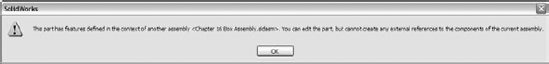
RMB click the part and select Edit Part from the list, or select the part and click the Edit Component button on the toolbar. A warning will display that the part has features that were created in the context of another assembly. You can edit the part, but you cannot add any more external references (in-context features) to it.
Toggle off the Edit Component button on the Assembly toolbar to exit Edit Part mode.
In Tools

Make sure that you are editing the Table Top part. It will not change colors as specified in the Tools
Open a sketch on the Front plane, and convert the four edges of the holes, as shown in Figure 16.16.
Cut the holes using the Through All setting. Again, be aware of the direction of the cuts. Toggle out of Edit Component mode and press Ctrl+S to save the assembly. Figure 16.17 shows the finished assembly.
Open the Machine Base Bracket part in its own window by selecting Open Part from the RMB menu. The part is shown in Figure 16.18.
Select the Front plane and select Insert
In this case, you do not need to add any of the items in the list, and so you can deselect any that are selected and click OK.
Note
Figure 16.19 shows the Locate Part panel of the Mirror Part PropertyManager. This panel does not appear when the feature is first created, although it probably should. This screen capture was taken with SolidWorks 2007 sp1.1, 32-bit version.
You can use Locate Part to move the part once it is inserted. If you do not use it, then the part is just positioned using its mirror plane. For this reason, it is best practice to mirror about one of the standard planes.
Also note that the template used for this part was chosen based on the settings at Tools
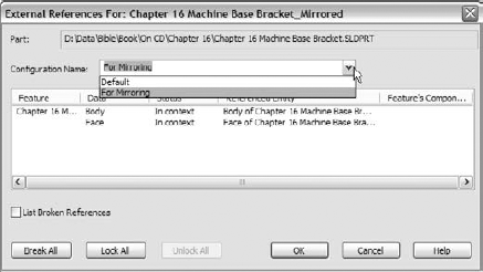
Notice that the new part is indeed a mirrored copy of the original. You can see that the "MADE IN USA" text on the bottom is backwards. Fortunately, a configuration exists specifically for this purpose. Change the configuration by selecting For Mirroring in the Configuration Name drop-down list in the External References dialog box, as shown in Figure 16.20. Notice that this configuration removes the extruded text from the model.
Add your own "MADE IN . . ." extruded text to the bottom of the part. Save the part.


Although in-context functions are powerful and seductive, you should use them sparingly. In particular, be careful about file management issues such as renaming parts and assemblies. The best approach is to use SolidWorks Explorer or the Save As command with both the parts and assemblies open.
Other external references include inserted parts, split parts, and mirror parts. These types of external references are often used in discussions on master models, which I address in a later chapter.