
IN THIS CHAPTER
Identifying the elements of an assembly
Using subassemblies
Using folders
Working with tree display options
Tutorial: Managing the FeatureManager
Chapter 5 offered a brief introduction to the basics of assemblies, how to put parts together, the basics of mating, and so on. The basic process for putting assemblies together remains the same for assemblies of any size, but once the assembly passes a certain point—and this point is likely different for each user or application—the assembly will benefit from some sort of organization or management techniques. This chapter introduces you to the tools and techniques that are available to help you manage performance issues as well as general browse-worthiness or searchability.
From Chapter 5, you know that an assembly has parts and mates. However, the simple tutorial in Chapter 5 did not go beyond this. While this tutorial got you started, it did not provide enough information to make you competent with assemblies. Real-world assemblies can become very complex. As the assembly grows in the number of parts and design requirements, you may need to add some of the following types of assembly elements (you may already be familiar with some of these parts from having worked with part documents):
Assembly equations
Assembly layout sketch
Assembly reference geometry (plane, axis, point, coordinate system)
Parts
Subassemblies
Folders for parts
Folders for mates
Mates
Assembly features (cuts that are made once the parts are assembled)
Component patterns
In-context reference placeholders
Smart Fasteners
Smart Components
Hole Series
These elements are shown in Figure 12.1.
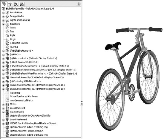
The three standard planes and the Origin are all familiar to you in the assembly FeatureManager design tree, as are the other standard items, such as the Annotations, Design Binder, and Lights and Cameras folders. These items offer the same standard functionality of their part document counterparts.
Assembly equations work mainly like part equations, but with some additional complications and considerations. For example, one of the additional features of assembly equations is the ability to drive the dimensions of one part from another part. The syntax is slightly different for this application, as shown in Figure 12.2. Overall, issues with equation order and using driven dimensions on the right side of the equation are the same between parts and assemblies.
Note
Equations are discussed in detail in Chapter 9.
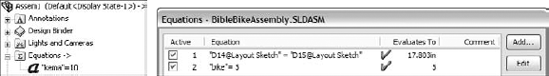
Notice the "->" symbol after the Equations folder in the Assembly FeatureManager. This means that there is an external or in-context reference.
Note
In-context references are discussed in depth in Chapter 16.
When one part drives another part in this way, the assembly must also be open to drive the relationship. If just the two parts are open individually, then changing the driving part does not update the driven part; because the relationship was created in the context of the assembly, the assembly must also be open to facilitate the change.
Link values and global variables also work in assemblies, but they do not work between parts. Local assembly sketches can use these functions, and the parts can use them when edited in the context of the assembly, but they cannot cross any document barriers (links must remain within a single document).
In past versions of SolidWorks, assembly equations had a hard time keeping track of parts when they were renamed, but in SolidWorks 2007, equations update regardless of how the part is renamed. This is also true of renaming the assembly. This includes renaming a part using the Save As command, using SolidWorks Explorer, or using Windows Explorer. It also includes redirecting the assembly to the new part name, as well as renaming the assembly using each of these techniques. If the assembly can find the part and recognizes the part as the one that it is looking for, then the equation will work.
The methods named above for renaming parts are not recommended; for testing purposes I was specifically trying to break the relationships in the equations.
While assembly equations are certainly a valid way to control part sizes, I would recommend using assembly or part configurations, possibly with design tables, to accomplish something similar.
Note
Assembly configurations are discussed in Chapter 14. Design tables are discussed in Chapter 10.
Warning
You may have unexpected results if a single dimension is controlled from more than one location. For example, if you have a part-level equation and an assembly-level equation, then one of the equations will be automatically set to Read Only and will not be used.
The layout sketch is a very useful tool for constructing complex assemblies or for laying out a mechanism in an assembly. Sketches in the assembly have the same characteristics as they do in the part environment. In Figure 12.3, the assembly layout sketch is indicated with a heavy, dashed line for emphasis.
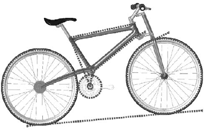
When combined with in-context techniques, assembly layout sketches can help to determine the shape of parts. You can also use layout sketches to mate assembly components to far more robust and dependable mates, rather than mating part to part. The sketch shown in Figure 12.3 is used for both of these techniques. The shape of the frame and the major pivot points are established in the 2D sketch. The wheels are also mated to the sketch.
When you use an assembly layout sketch for either the in-context part building or simply part positioning, the main advantage that it offers is having a single driving sketch that enables you to change the size, shape, and position of the parts. You can use as many layout sketches as you want, and you can make them on different sketch planes. This enables you to control parts in all directions.
Planes and axes are frequently created within assemblies to drive symmetry or placement of parts. You can use assembly layout sketches to create the reference geometry entities. When you create reference geometry within the assembly in this way, be aware that the normal history-based parent/child relationships are still followed. The familiar icons for reference geometry entities are also used in the assembly tree.
Because features such as sketches and reference geometry are history-based and found in the assembly tree, at least a portion of the assembly FeatureManager is history-based. However, not all of it is. For example, the list of parts and subassemblies is not history-based.
Sketches and reference geometry may appear before or after the list of parts, subassemblies, and mates. All of the remaining entity types that can be found in the assembly FeatureManager are also history-based features, and you can reorder them in the tree. However, several situations can disrupt the process. Under normal circumstances, sketches and reference geometry at the top of the assembly FeatureManager are solved, then the parts are rebuilt if required, and then the mates are solved. This ensures that the sketches and reference geometry are in the correct locations so that if parts are mated to them, then all of the components end up being the correct size and in the right position.
Assembly-level reference geometry can be created that references component geometry instead of layout sketches. This creates a dependency that changes the usual order. For example, the planes are usually solved before the part locations, but when the plane is dependent on the part location, the plane has to be solved after the part. If a part is then mated to the plane, you are beginning to create a dependency loop, such that the plane is solved, followed by the part, then the plane again because the part has moved, and then the mate that goes to the plane has to resolve the part.
Note
If you are a bit confused by all of this, don't worry. You can simply follow this rule: Do not mate to anything that comes after the mates in the assembly FeatureManager tree. This includes assembly planes or sketches that are dependent on part geometry, assembly features such as cuts, in-context features, component pattern instances, Series Holes, or SmartFasteners.
This is probably a lot of information for a new user, but if you remember this rule, then you can avoid creating models with circular references, where A is dependent on B, which is dependent on A—a never-ending loop that causes major problems for large assembly rebuild times.
Parts and subassemblies are shown with their familiar icons in the design tree. You can reorder and group them in folders, which is covered in the next section.
In manufacturing, once parts are assembled, secondary machining operations are sometimes applied to them to ensure that holes line up properly, or for other purposes. For example, assembly features can be cut extrudes, cut revolves, or hole features. These features appear only in the assembly, not in the individual parts.
You should not confuse assembly features with in-context features. In-context features are created in the assembly with a reference between parts, but the sketch and feature definition are in the part itself.
Because the options for locally defined patterns are comparatively limited, users generally like to use part feature patterns to drive the component patterns when possible.
Note
To improve performance, it is best to pattern subassemblies if possible. If it is not possible, then patterning a group of parts is the next best option. Making multiple patterns, one for each part, is an inefficient way to accomplish the same thing.
It is difficult to get a good picture of assemblies in general without including a discussion about in-context references, but to treat the subject properly, it also requires its own section. When you create a reference between parts in an assembly, the assembly needs to remember which parts are involved in the reference. The parts also need to remember which assembly was used to create the relation because the parts are positioned in the assembly, and the reference has meaning only with regard to a particular relative position between the parts.
When you create the relation, a placeholder has to be left behind in the assembly to hold this information. This placeholder is called an Update Holder. The Update Holders do not display by default. To see them, you must RMB click the top level in the FeatureManager and select Show Update Holders. They only exist when in-context references exist in the assembly, and there is one Update Holder for each in-context reference. You cannot do very much with the Update Holders, other than query them for parent/child relations and to list the external relations, but they serve as a reminder that you have in-context references to maintain. Several years ago, they were displayed by default, but they were later hidden by default, presumably because users were confused by the presence of something that you could not do anything with. In-context modeling methods are often scorned by some users, and if you have a list of 50 or 60 Update Holders, then you may be perceived as an overzealous novice. For more information on this feature, see Chapter 16.
Note
Smart Fasteners, Toolbox, and the Hole Wizard are discussed in detail in Chapter 17.
The first tool for organizing assemblies is the subassembly. A subassembly is just a regular assembly that is used as a component in another assembly.
Note
The number of levels of subassemblies is not limited to a specific number, although for different sizes and types of assemblies, I encourage you to establish a best practice for your company. For example, establish a guideline that suggests that subassemblies of 100 parts or less go no deeper than three levels.
You can use several criteria to determine how subassemblies are assigned:
Performance
Bill of Material
Relative motion
Pre-fabricated, off-the-shelf considerations
According to assembly steps for a process drawing
To simplify patterning
The underlying question here is based on the multiple functions of your SolidWorks assembly model. Is it primarily a design tool? A visualization tool? A documentation tool? A process tool? As a design tool, the assembly is used to determine fits, tolerances, mechanisms, complex shapes that span parts, and many other things. As a visualization tool, it simply has to look good and possibly move properly if that is part of the design. As a documentation tool, it is important how the model relates to the Bill of Materials, and the order in which subassemblies are added. As a process tool, you need to be able to show the assembly in various intermediate states of being assembled.
I have seen companies create multiple assembly models for different purposes. Sometimes the requirements between the different methods are contradictory and cannot all be met at the same time with a single set of data. Again, depending on what information you need to be able to extract from your SolidWorks models, you may want to approach assembly modeling and organization differently.
You can create subassemblies from parts that already exist in an assembly. To do this, select the parts that you want to add to the subassembly, and then select Form New Subassembly Here from the RMB menu. You are then prompted to assign a name to the new subassembly.
Warning
When creating a new subassembly from existing parts or when moving parts into or out of a subassembly from the upper-level assembly, some things may be lost. For example, mates are moved from the upper level to the subassembly. If you have in-context relationships, they may be removed. Operations that create subassemblies cannot be undone easily.
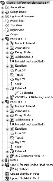
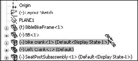
Once you have created the subassembly, you can add or remove components using the drag-and-drop method. For example, Figure 12.5 shows the cursor that indicates that the part named Left Crank is being moved into the subassembly named bike crank. To move a part out of a subassembly, simply drag the part into the upper-level assembly.
Note
When you are dragging a part out of an assembly and into another one, you may again see the cursor symbol that appears in Figure 12.5. If you do not want this to happen, then hold down the Alt key while dragging. The cursor symbol changes to the Reorder cursor (a reversed, L-shaped arrow), and the part is placed after the subassembly rather than within it.
Along with the RMB menu option Form New Subassembly Here, which takes existing parts and puts them into a newly created subassembly, you can use another option called Insert New Subassembly. The names of these functions do not adequately describe the difference in what they do. Insert New Subassembly inserts a blank subassembly at the point in the design tree that you indicate by right-clicking it. You can place components into the subassembly by dragging and dropping them from the main assembly, or you can open the assembly in its own window, and insert parts by using the usual methods.
If you would like to get rid of a subassembly but want to keep its parts, then you can use the Dissolve Subassembly option through the RMB menu. This option has some of the same consequences of the Form New Subassembly Here option in that mates are moved from the subassembly to the upper-level assembly, and you may lose in-context relations and assembly features.
Performance in SolidWorks is a euphemism for speed. Subassemblies can contribute to speed-saving modeling techniques by segmenting the work that the software needs to do at any one time.
The mates that contribute to putting the pieces of an assembly together are solved at the level of the top assembly. Under normal circumstances, subassemblies are treated as static selections of parts that are welded together, and their mates are not solved at the same time that the top-level assemblies' mates are solved. This segmenting of the mates leads to improved performance by only solving one set of mates at a time.
Mates are usually solved as a single group unless there is a special situation, such as mates to in-context features, component pattern instances, or an assembly feature, all of which have already been described in this chapter. When one of these situations occurs, the mates have to be divided into separate groups or solved multiple times. This is done transparently behind the scenes so that the user does not have to worry about it.
When you create subassemblies, the mates for these parts are not solved in the upper-level assembly. This means that if a subassembly is a mechanism, the mechanism does not allow Dynamic Assembly Motion in the upper-level assembly. For example, in Figure 12.6, the front fork is a linkage mechanism, but it is also a subassembly. Without reassembling the parts of the fork in the upper-level assembly, you can allow the mates from the fork subassembly to be solved in the upper-level assembly by using an option in the Component Properties dialog box, which is also shown in Figure 12.6. When you select the Flexible option in the Solve as section, you enable the mates of this subassembly to be solved in the upper-level assembly.

To access the Component Properties dialog box, RMB click the subassembly and select Component Properties from the menu.
If you have assemblies that were built in older versions of SolidWorks (such as SolidWorks 2001+), mates used to be split up into multiple mate groups, which represented the groupings that mates were solved in, which was forced by mating to the history-based features in the assembly FeatureManager. SolidWorks no longer displays mate groups, but the groups are still used in the background to solve mates.
The Bill of Materials, or BOM, is a table that is placed into a drawing of an assembly. This table shows the parts used in the assembly and includes other information, such as part numbers, descriptions, and custom property data.
Note
SolidWorks BOM functionality is discussed in depth in Chapter 24.
Businesses often represent assemblies and subassemblies in various ways by using MRP or ERP software (Manufacturing Resource Planning or Engineering Resource Planning). The methods that accountants and manufacturers use to organize assemblies are not always the same as those that an engineer or designer might choose, but some companies require the BOM on the drawing to match the MRP or ERP Bill of Materials.
Note
When forced into modeling something in an unnatural way to satisfy an outside requirement such as special BOM requirements, it might be best to detach the unnatural part and model normally. In the situation mentioned here—where MRP is forcing how the assembly is put together by requiring the BOM to match MRP—I recommend separating the BOM from the assembly structure. This ensures that the BOM becomes a manually maintained document, rather than building an assembly that makes other SolidWorks functions difficult. Alternatives to this approach would be to make configurations or entirely new assembly documents to drive the BOM.
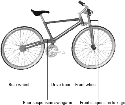
A more natural way to group subassemblies is by considering relative motion. In the bicycle example, each wheel is a separate subassembly because it moves as a unit relative to the rest of the assembly. Figure 12.7 illustrates where relative motion might be on the bicycle.
Grouping subassemblies by relative motion is great for assembly modeling, but it does not usually reflect product reality very well. Using this method, you often end up with parts in the subassembly that would have to be disassembled in order to actually put the physical parts together. However, if your only consideration is ease of modeling, then this is probably the method to use.
If you are modeling a product that is created from a shopping list of purchased components, then it may make the most sense to organize your subassemblies into groups of parts that are purchased together. In fact, purchased subassemblies are often modeled as single parts, except when relative motion is required in the purchased assembly.
For example, in the bicycle assembly, the sprockets on the rear wheel are purchased as a separate unit, and yet the part that mounts onto the wheel moves relative to the sprockets that are driven by the chain. This is an example of a purchased part that would be modeled as a subassembly to show relative motion. The bicycle chain, another purchased subassembly, has not yet been added to this assembly, and is a more complex model. The desire to show all of the individual links moving through the path may override both the complexity of assembling it and the performance considerations of exercising all of the mates.
Although the BOM method of organizing assemblies sometimes leads to unnatural solutions, you should not discard it altogether. If you can devise concessions in order to make the BOM work automatically, then you should do this.
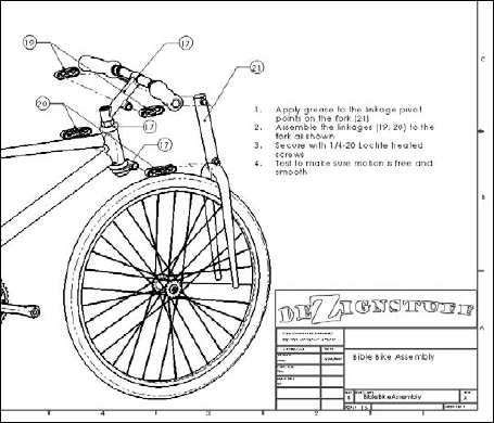
Manufacturing and assembly processes need to be documented as well as individual part design. You often need to create exploded-view assembly instructions for manufacturing or service documentation at each step of a multi-step assembly process. Figure 12.8 shows a page of this type of process documentation.
This is certainly a task that is different from the initial design or modeling of the assembly, and it may require an entirely separate model. Generally, you can perform the different steps by using a separate configuration for each process step, with exploded views for each configuration.
Balloons number the parts according to the item number that is used in the BOM, but of course you do not know the item numbers until the BOM is created. You can influence the item numbers by reordering the parts in the assembly (which is discussed later in this chapter), by manually editing item numbers, or by manually numbering the balloons. All of this is discussed in detail in Chapter 24.
Each step corresponds to an assembly configuration (discussed in Chapter 14), and you can place them on a separate sheet of the drawing (discussed in Chapter 21). Each configuration can have multiple exploded views, if necessary, to show all of the steps.
The most efficient way to pattern large numbers of components in an assembly is to pattern a single subassembly with all of the components to be patterned in it. While this may not be easily combined with some of the other considerations that were mentioned previously, it is another option that you can use to organize assemblies.
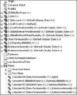
Folders are primarily used in the assembly FeatureManager for grouping parts and mates into either special classifications for easy browsing, or groups that can be easily hidden and shown, or suppressed and unsuppressed, as appropriate. Figure 12.9 shows some examples of these folders.
You can add folders to the assembly FeatureManager in one of two ways:
Add to a new folder
Create a new folder
To use the Add To New Folder tool, RMB click a component or mate (or selection of components or mates) and select Add To New Folder from the menu. This moves the component or mate into the folder. Folders do not affect the assembly in any functional way; they are simply for organization, to speed browsing and selection.
To move an item into an existing folder, just drag the item (component or mate) onto the folder. If the folder is expanded, showing its contents, then you can also drag the item as if you were reordering a feature in the FeatureManager of a part, and drop it in the list of items where you would like it.
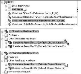
If you are dragging a part or assembly and trying to put it immediately after an assembly, then a cursor may appear, like the one shown in the center in Figure 12.10. This cursor means that the part is going to become part of the assembly. If this is not what you are trying to do, then hold down the Alt key while dragging; the part is placed into the folder immediately after the assembly, instead of being made a part of the assembly. The third image in Figure 12.10 shows the cursor with the Alt key pressed.
There are times when you may want to reorder items in the assembly tree. For example, you may want to place items close to one another in the tree, or you may be preparing to put items that are next to one another into a single folder.
You can reorder mates simply by dragging them. Mates display in the order in which they are created, but the order is not significant. They can be reordered however you like.
Components also display in the order in which they are added to the assembly, and you can reorder them in any way you like.
Note
It is often useful to have an ordering strategy that helps you to work with the model. I usually try to keep the biggest parts, or the parts that everything else is mated to, or the part that is treated as "ground," as the first part in the assembly. The fasteners and other cosmetic or BOM-driving parts are put at the end of the tree, usually in a descriptive folder.
Display options for items in the FeatureManager are often overlooked, but can be useful for displaying data about parts, subassemblies, mates, and features. Figure 12.11 shows the RMB menu options.
Note
All of these options are available for parts and drawings as well, except for the View Features option and the View Mates and Dependencies option, which are related to assemblies.

If you are so thorough that you have added descriptions to your features, then you are doing well. This option refers to the descriptions of features in the parts. The middle image in Figure 12.11 shows a section of the FeatureManager for the bicycle frame part; some of the features have had descriptions added with both of the options for feature names and feature descriptions turned on. The image to the right in Figure 12.11 shows the result of turning off the feature name, with only the feature description option turned on. If no feature description has been created, then the feature name displays. Feature descriptions always appear in double quotes.
The image to the left in Figure 12.12 shows the default arrangement of displaying component and configuration names in the assembly FeatureManager. This example uses the rear wheel assembly from the bicycle assembly. In assemblies, you cannot turn off the component names and the component descriptions. SolidWorks issues a statement when you try to turn off both the name and the description, saying, "You cannot hide both the component name and the file name. At least one must be visible in the tree."
The message in the previous paragraph distinguishes between the filename and the component name that is listed for individual parts or subassemblies in the assembly FeatureManager. You can specify the component name in the Component Properties dialog box by RMB clicking the component in the assembly FeatureManager and selecting Component Properties.

However, you can assign a component name for a component that is different from the filename only if a special setting is turned off (the setting defaults to on). You can access this setting through Tools
After going through the preceding steps, you still receive the warning message about the filename and the component name. This is apparently an "unintended feature," or bug, and should likely say that you cannot turn off both the component name and the component description at the same time.
There may be a situation where you want to show a name other than the filename in the FeatureManager. For example, your company may be using sequential part numbers for the filenames, which are difficult to read, and you want something descriptive in the design tree so that you do not need a cross-reference sheet next to your computer that equates filenames to meaningful descriptions.
If you prefer, you can avoid a lot of problems by just using the part description instead of the filename or the component name. The choice is up to you.
Note
Because the component name options are convoluted, obscure, and will need to be set on each computer where you would like to use them, I do not recommend them. It is simpler and more reliable to use either the default component name (which is the same as the filename) or the component description.
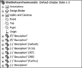
One of the problems with using the component description is shown in Figure 12.13, where the user did not enter proper descriptions for the parts, and SolidWorks used the default description in the templates. The tire and spokes use configurations, which display in the figure.
The last set of options, shown in Figure 12.11, defines what displays under the name of each component. The default setting is for the part's features or the subassembly's components to display, just as if the part or subassembly were open in its own window.
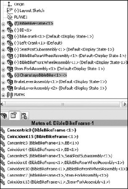
The View Mates and Dependencies option can also show the features, but they are placed into a separate folder. This option makes it very easy to see the mates that are assigned to an individual component. For example, in Figure 12.14, the image to the right shows the mates directly under the BibleBikeFrame part. This often makes troubleshooting much easier because it isolates the mates for a single part. Notice also that the first folder under the part name in the image to the left in Figure 12.14 is the Mates folder. This indicates that, regardless of whether you choose to display mates or features, you always have easy access to the other type.
Another technique for displaying mates is to split the FeatureManager and to show the PropertyManager in one pane. As a result, any parts that are selected show their mates in the PropertyManager pane. If two selected parts have mates in common, then the common mates appear in bold type, as shown in Figure 12.15. This is an extremely useful method for looking at mates.
Warning
This function does not appear to work in SolidWorks 2007 sp1.0, although it does work properly in sp0.0. Service Pack 1.0 was the latest available service pack at the time that this chapter was written. SolidWorks knows about the bug and has labeled it a "regression," which means that it will receive priority in subsequent fixes. The fix may be available in sp2.0.

This tutorial uses the BibleBikeAssembly.sldasm file found on the CD-ROM for Chapter 12. Follow these steps to learn about managing the FeatureManager:
Create a new subassembly within the existing assembly using the parts BibleBikeFrame and ChainstayBibleBike. Name this new assembly FrameAssembly.SLDASM.
Reorder the new FrameAssembly to the top of the design tree.
Reorder the other parts and assemblies so that the bigger assemblies appear higher on the list, and the parts appear at the bottom. (Remember that the Alt-drag option to prevent a component from being placed into a subassembly.)
Drag the part called BB (for Bottom Bracket) into the FrameAssembly (drag without using the Alt key). The assembly FeatureManager at this point is shown in Figure 12.16.
Select both wheels and then click Add To New Folder from the RMB menu. Name the new folder Wheels, and move it to the bottom of the tree.
Expand the Mates folder, select the first four mates, and put them in a new folder (select Add To New Folder from the RMB menu). Name the new folder Centering Mates.

Assemblies are more than simply parts and subassemblies put together with mate relationships; several other types of features and placeholders can also exist in the assembly FeatureManager. Organizing assembly components is fairly straightforward, and can offer benefits for finding parts as well as controlling suppression and display states globally.
The assembly FeatureManager contains several options for the data to display for subassemblies, parts, configurations, and features within. Remember that all of this data that you include in your SolidWorks documents can be accessed and reused later on, and so it is worth the effort. Descriptions can be very important, both at the part level, and also for features and configs.