IN THIS CHAPTER
Using library features
Creating library features
Tutorial: Working with library features
Library features are features that you create once and re-use many times. They are intended to be parametrically flexible to fit into many types of geometry, but they can also be of a fixed size and shape. All of the information that you have learned in previous chapters about designing for change, and design intent, will be used here, and you will also learn how to create, use, and store library features in this chapter.
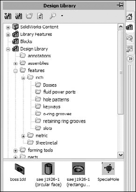
Library features reside in the Design Library, which is located in the Task pane to the right of the graphics window.
Tip
You can actually detach the Task pane from its docking location and move it wherever you want, leave it undocked, or even dock it to the left side of the screen.
If you are a long-time SolidWorks user, then you may still know the Design Library as the Feature palette. Another change to the old library features and palette features is that they have been combined, thus removing some of the limitations of the old palette features.
You can use library features for snap rings, grooves for o-rings, custom holes (you can even customize a Hole Wizard hole and put it in the library), mounting bosses for plastics, mounting hole patterns, electrical connector holes, and so on.
One very useful aspect of library features is that they can be driven by configurations and design tables. Once the feature is in the part, the configurations are still available, and so you can change the config of an applied library feature at any time.
You can also link a library feature to an external file. This enables you to change a feature or set of features in several parts at once, if they are all externally linked to the file.
Library features are simple to use, but difficult to set up. For that reason, this chapter discusses using them first, so that you know what kind of behavior you are trying to create. As a result, setting them up should make a little more sense.
To use a library feature, you just drag and drop it onto the appropriate geometry. You are then prompted to select references in the new part that match the base geometry that the library feature is attached to. You can be fairly creative with references, but one of the goals is to make the library feature work with as few references as possible, in order to make it easy, fast, and reliable to use.
SolidWorks software installs with several sample library features in the Design Library. The following demonstration uses some of these standard library features. Later, you can add library features from the CD-ROM to the Design Library.
Library features work best if they go from a certain type of geometry to a similar type of geometry, for example, from rectangular to rectangular, or from circular to circular. This is because the relations or dimensions that link the feature to the rest of the part tend to be dimensions from straight edges or concentric sketch relations. Of course, there are other ways of applying library features, but these are the most prevalent. Library features can be applied unconstrained and then constrained, or moved later, but the process is cleanest when it all just falls together correctly the first time.
You do not have to save the part or do anything special before applying the library feature. All you need to do is find the Task pane. The Task pane is the window that flies out from the right when you open SolidWorks. You may have turned it off and forgotten about it, in which case you can turn it back on by selecting View
The Task pane automatically closes when you click outside of it unless you pin it open using the push-pin icon in the upper-right corner of the window. When you do this, any toolbars that appeared on the right side of the Task pane control tabs are moved out and positioned between the graphics window and the Task pane, which now remains open by default.
You can also detach the Task pane by dragging the bar at the top of the pane. Figure 18.1 shows the Task pane docked to the right side of the SolidWorks window.
Tip
If you are using dual monitors, you can drag the detached Task pane onto the second monitor, which allows you to use the Task pane, and at the same time gives you more room in the graphics area. This must be done each session; the Task Pane does not remember positions on a second monitor.
Open a new part and create a cylinder using any method you want (for example, extrude, revolve). Make the diameter three inches, and the length a little more than one inch.
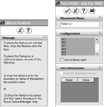
In the Inch features folder, click the folder called o-ring grooves. The first feature in the list is called face static – gas. Drag-and-drop this feature onto the end flat face of the cylinder. As shown in the image to the left in Figure 18.2, the PropertyManager displays a yellow information panel explaining the process.
The next step is to select the configuration, as shown in the image to the right in Figure 18.2. Not all library features have multiple size configurations, but these ones do. The configs in this case are driven by design tables. Select configuration 330.
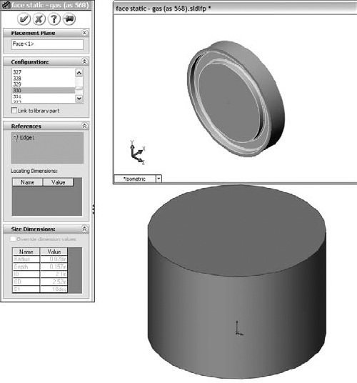
When you select the configuration, the interface changes. In this case, only a sketch relation locates the feature; it is not located by dimensions. Notice that in the References panel shown in Figure 18.3, there is an Edge entry with a question mark. This means that the library feature needs a circular edge to locate it. Notice that a small window appears, displaying the library feature. You may not be able to distinguish it in Figure 18.3, but the circular edge around the face that the library feature is on is highlighted in green. This indicates that you need to select an edge that has the same relation to the library feature as the highlighted edge. Pick the circular edge of the part on the end of the cylinder where you want to place the library feature.
Next, use a rectangular part where the library feature is located by using dimensions rather than sketch relations. Create a rectangle, 1.5 inches by 2 inches, and extrude it to about 2 inches in depth.
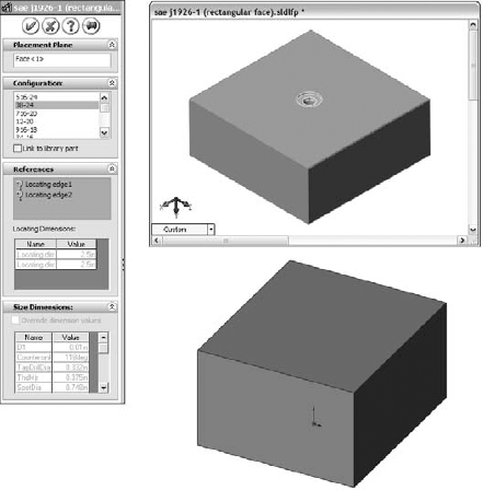
Next, in the Design Library, browse to features, then inch, and then the fluid power ports folder, and drag the sae j1926-1 feature onto the end of the extruded rectangle. Select the 38-24 size from the configurations list. A window appears, prompting you for reference selections, as shown in Figure 18.4.
Tip
It is often helpful to orient the part that is receiving the library feature in the same way as the part shown in the preview window. This helps you to visualize which edges to select.
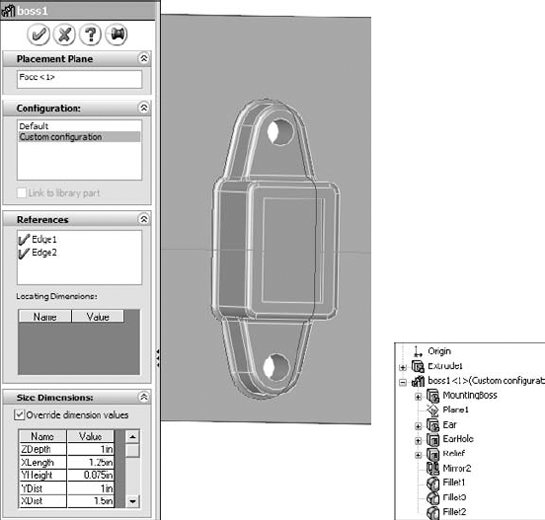
After the locating edges have been identified, the Locating Dimensions box becomes active, and you can change the values of the dimensions to locate the feature. Further, in the Size Dimensions pane at the bottom of the PropertyManager, clicking the Override Dimension Values option allows you to change dimensions of the feature itself.
When you use a library feature with a design table, the design table is not brought into the part with the library feature. If the part already had a design table, this would cause multiple tables, which is not currently possible in SolidWorks.
If you override the feature dimensions when feature configurations already exist, then a new configuration is created in the list of feature configurations called Custom Configuration. It appears that multiple custom configurations are not allowed, and so if you have to make changes, then you must ensure that they are right before you use the library feature in a part.
The Design Library has other functions besides library features. For example, you can use it as a repository for other items that you use frequently.
You can store commonly used annotations in the Design Library. If you look at the Annotations folder with the default sample annotations, you see a combination of symbols and blocks. You can use symbols and notes in 3D models, but you can only use blocks in sketches or 2D drawings. Keep in mind that not all annotation types can be used in all places.
Annotations can be stored in the library as favorites or blocks. Many file extensions are used for different types of favorites, but they typically begin with *.sld and end with fvt, as in *.sldweldfvt. Figure 18.5 shows the default location of the Design Library, and the Thumbnail view of the favorites and blocks in the Annotations folder.
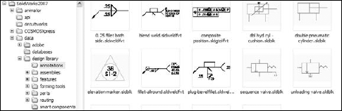
If you frequently work with different types of annotations, then you should organize the library into sub-folders to separate symbols, annotations, and blocks, and move these folders to a different location. By default, the Design Library folders are found at <SW install dir >datadesign library. You should store them to another location, not in the SolidWorks installation directory, but in an area that you have selected to maintain SolidWorks data between releases. For example, I have a folder at D:Library that contains folders for macros, templates, library features, library parts, favorites, and so on. You can easily back up or copy these files from one computer to another, although you must quit SolidWorks before making these changes.
After moving the library, you have to point SolidWorks to the new location. To do this, select Tools
The Design Library can also store commonly used library parts. One of the advantages of using the library for parts is that on placement into the assembly, if configurations are available in a part, then a window pops up, enabling you to select which configuration to place into the assembly.
Note
In many cases, using the Design Library for Library Parts is thought to be an acceptable replacement for the automated function of Toolbox. If you use Toolbox to make the parts and populate them with configurations, and then save the parts out of Toolbox and into the Design Library, many options, including naming conventions, and more flexible use of custom properties become available that are not available through Toolbox.
Figure 18.6 shows the configuration selection window. Note that this is alphabetically listed, and you can type in the box to go to the configuration that you want.

Parts inserted from the library parts folder can also take advantage of the Mate References functionality in the same way as Toolbox, by allowing parts to snap into place.
Sheet metal forming tools are only mentioned here as a part of the library. They work much like other library features, but they do so within the specialized functions of sheet metal parts in SolidWorks. Sheet metal forming tools are discussed in Chapters 29 and 30.
You can use library assemblies in SolidWorks in the same ways that you use library parts, because they are inserted into the top-level assembly as a sub-assembly. For sub-assemblies that require motion, such as universal joint sub-assemblies, you can set the sub-assembly to solve as flexible.
Tip
When saving assemblies to the library, it is recommended that you put the parts in a separate folder to segregate the parts of different assemblies.
Routing is a separately purchased add-in that is included with SolidWorks Office Premium. It includes piping, tubing (rigid and flexible), and wiring. Routing makes extensive use of libraries and automation, but is not part of the scope of this book.
Smart Components are components that resize by automatically selecting configurations, depending on the size of the geometry onto which they are being dropped. For example, a clamp with many sizes driven by configurations would select the correct config when dropped onto different sizes of cylinders. This is a very useful tool. Smart Components are discussed in Chapter 19.
When you save library features to the library, they use the file extension, *.sldlfp (library feature part). They must contain some base geometry, which simulates the part onto which the feature will be dropped. The base geometry is not transferred to the new part; only features that are marked with the "L" in the FeatureManager (for Library) are transferred to the new part. Figure 18.7 shows the FeatureManager of a library feature part.

When creating a library feature, the first problem that you need to solve is how the feature will be located on a new part. Does it need to be placed on cylindrical parts, rectangular parts, other types of shapes, or does this matter at all? Will the feature be located by using dimensions or sketch relations, or will it just be placed underdefined and later fully defined manually rather than automatically?
You may have noticed in one of the earlier examples that the sample fluid power ports had two versions of the same feature. One version is intended for the feature to be placed on the flat end of a cylinder, and the other version is intended to be placed on a rectangular face.
Library features can contain multiple features of different types. They may add and remove material, even within a single library feature. However, a few limitations exist. For example, they require a base feature, and multibody features and external references are not allowed, nor are sheet metal, weldments, or molds. In addition, you cannot add scale features to the library, nor can you apply library features to an assembly.
To start a new feature, the first decision that you need to make is what shape to make the base. Is the feature a type that is usually going to go onto a single shape or multiple shapes? Regardless of your decision, you or whoever ends up using the feature will have the flexibility to change, or simply not use, the relations when you place the feature.
For this example, I use a rectangular base. The library feature that I want to create consists of two boss extrudes, a cut extrude, and several fillets. Here is how it works:
First, you need to create a rectangular extrusion. The size should be bigger than the feature that goes on it, and representative of the face of the end part onto which this feature will typically be placed.
Next, in beginning to create the features that you want to reuse, it is very important that you pay attention to any references outside of the sketch; these include absolutely anything outside the active sketch, such as the sketch plane, references to edges, the Origin, other planes, other sketches, and axes. Although these references are allowed, each reference to anything that is not already part of the library feature must be reconnected when you place the feature on the part. The ideal situation is obviously a single drag-and-drop, but generally speaking, at least one other step is usually needed. The initial drag-and-drop determines the face for the feature to start from, and from there, you usually need to locate features, either by using relations or dimensions. A concentric dimension locates the feature in a single reference selection of a circular edge (although it may also need to be rotated), and dimensions typically require a dimension in the X dimension, and another one in the Y dimension.
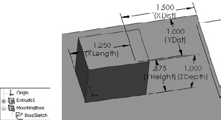
Figure 18.8 shows the base feature and the first feature of the library feature. The only relations between the sketch of the library feature and the base feature are the sketch plane and the two dimensions.
Note
Notice that names have been assigned to all of the dimensions, sketches, and features. This is because the dimension names all display in the interface. If you look back to Figure 18.4, in the Size Dimensions pane, dimension names make it easy to know which dimension to change, whereas the D1 dimension leaves you guessing as to what it applies to.
You should ensure that subsequent features after the first one reference only the first feature of the library feature (which is the second feature in the part). This is not a mandatory requirement, but a helpful guideline. You can make additional references, but they should be limited to the same items that were already referenced, if possible. Users who model carelessly or do not pay attention to what they are doing, typically have trouble making library features that function and are easy to use.
Now you can add the second extruded feature, being careful to reference only geometry that is going to move with the library feature. Figure 18.9 shows the newly added feature. If you would like to follow along with the building of this feature, you can open the part from the CD-ROM under the filename Chapter 18 First Library Feature.sldprt.

Notice that a plane has been added. The plane is made to only reference geometry that is internal to the library feature; it is perpendicular to an edge at the midpoint, which simultaneously locates and orients the plane correctly to enable it to be used to mirror the Ear feature.
Also notice that the EarSketch uses the same face reference from the base feature. This will appear in the Reference list as a single reference.
Note
SolidWorks has made some changes that affect library features in two ways that may not be immediately obvious. First, before SolidWorks allowed multibody parts, the first feature of the part was always called the base feature. This terminology remains, even though the concept of a base feature is obsolete. (The first feature in a part may be reordered so that a different feature becomes first.)
Second, SolidWorks used to distinguish between palette features and library features. Palette features were limited to a single reference, and library features were a bit less user-friendly but more powerful. They have been combined and improved to what we have today.
You can use two methods to save a library feature. You can either drag-and-drop into a Design Library folder, or use the Save As method. Because Save As is a little more common, I will describe it first.
The first step in saving the library feature is to select all of the features in the FeatureManager that are intended to be a part of the library feature. Collapse the features first so that the sketches belonging to features are not selected. If the sketches are selected you may get a warning message saying that all of the selected features cannot be used in the library feature. Do not worry; the sketches still will be included.
Tip
Remember that you can Ctrl-select individual features, Shift-select a range, or click-and-drag a box in the FeatureManager to select multiple features. Also keep in mind that if you do not select a feature (other than the base feature), then it will not be placed into the part when you insert the library feature. If there were any relations to the omitted feature, they may display as errors or warnings when you place the feature.
With the features selected, click File, Save As, and under Files of Type drop-down list, select the *.sldlfp file type. Browse to the Design Library folder, and save the part. Figure 18.10 shows the FeatureManager of the finished library feature.

During the Save As process, a new folder was added to the Design Library named Bosses, as shown in Figure 18.10. Notice the new icon for the library feature in the lower window. You may notice that some of the default library features saved in the Design Library have a bluish background. This occurs because of the SolidWorks viewport background color, which you can set in Tools, Options, Colors. Even if you never see that color because you are using a gradient background, SolidWorks still uses the color specified by that setting as the background when saving thumbnails and previews. I always set this color to white for this reason, so that document backgrounds in previews do not have the blue color.
You may want to orient and zoom the library feature before saving it, so that it displays clearly in the panel. One of the techniques that I like to use is to make the base feature a different color than the library feature itself; this helps you to more easily determine what is the geometry that will be transferred and what is just dummy material.
Tip
Figure 18.11 shows various settings for displaying the icons in the Design Library. Which one you select will depend on your screen resolution, the number of icons that you want to display, and the quality of the preview images.

The real test for a library feature comes when you actually use it. This feature is recreated perfectly on the new part, but I noticed one problem. When the feature was placed, it was 90 degrees away from the orientation that I wanted it to be in. It seems that the only way to make the feature rotatable is to create it with parallel and perpendicular relations rather than horizontal and vertical ones, so that one of the references can act as a rotation reference.
Figure 18.12 shows the completed library feature placed on a part.
Once you place a library feature on a part, it can be edited, unless you select the Link To Library Part option in the Configuration pane, in which case the feature is driven externally from the *.sldlfp file.
One of the available options is to dissolve the library feature so that all of the constituent features become regular features in the main part.
When creating a library feature from an existing part, you use essentially the same process, but it is actually somewhat more difficult to achieve the correct results. It is best to remove all of the features that do not either form the base feature or go into the library feature itself. This can cause a lot of broken references. It may be better to use a different technique such as creating a new part with only the base feature. You can then Ctrl-drag the desired features from the existing part to the new part, set up the rest of the library feature, and save it with a *.sldlfp extension.
You can also create a library feature by dragging and dropping, although there are some limitations with this technique that seem to override the convenience. However, there is a workaround for the biggest limitation. If you select faces from features and drag them into the lower Design Library window, then an Add to Library PropertyManager interface appears to enable you to start creating a library feature. The Add to Library PropertyManager interface is shown in Figure 18.13. You must select the features from the flyout FeatureManager. This is the source of one of the limitations. In our example, the plane cannot be selected by this method. The workaround for this is to complete the feature without the plane, RMB click the icon in the Design Library window, and then select Open. With the library feature open in its own window, RMB click the plane feature and select Add to Library; that individual feature is then added.
You can add folders to the library in two ways, either by RMB clicking in the Design Library window and selecting New Folder, or by using the Windows Explorer interface. Another RMB menu option is Add Existing Folder, which enables you to add a folder from another location to the library. The folder is not moved or copied, but a shortcut is added to the Design Library, and the contents appear in the lower pane.
Tip
After a library feature has been edited, or folders or documents have been added to the library using Windows Explorer, you can press F5 in either the lower or the upper window to update the display for that window, or by using the Refresh icon located at the top of the Task pane.
This tutorial guides you through customizing a Hole Wizard hole to use as a specialty library feature, then storing it in the library, editing it, and placing it in a part. Follow these steps:
Open a new part, and create a rectangular base feature, about three inches high by three inches wide, and three inches deep.
Pre-select a flat face and start the Hole Wizard.
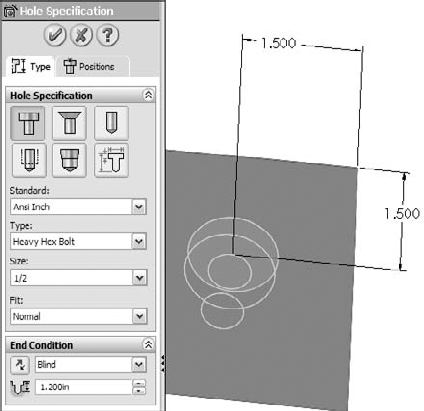
Create a counterbored hole for a Heavy Hex Bolt, 1/2-inch, Normal Fit, Blind, 1.2 inches deep. Locate the hole with dimensions from two perpendicular edges, as shown in Figure 18.14. Click the green check mark icon to accept the hole settings.
Select Tools

Double-click the counterbored hole feature in the FeatureManager to show the dimensions. RMB click one of the dimensions that you created to locate the center of the hole, and select Properties.
Rename the dimension using different names, so that they will have meaning when you place the dimension, such as XDir, or YDir. Do this for both dimensions.
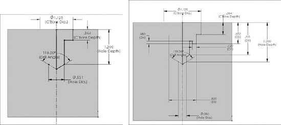
Edit the second sketch of the hole. Figure 18.15 shows what the sketch should look like before and after the edit.
Warning
Do not delete any of the named dimensions in a normal or revised Hole Wizard hole. SolidWorks has a checking mechanism that looks for these names, and it will display an error if the named dimension is not there. If there is no use for the dimension, it still has to be there, although it does not need to be used for its original use. You could rename another dimension with the name or simply dimension the centerline or an otherwise unused construction line. It does not matter about the function of the dimension, as long as there is a dimension with that name in the sketch.
Tip
You should also name any new dimensions that you may want to change. These dimensions will have more meaning when you are placing the feature if they have names.
Tip
Remember that to get the diameter dimensions shown in Figure 18.15 (instead of radius dimensions), you must use the dimension tool to select the centerline (construction line) and the line or endpoint on one side, and then move the cursor to the other side of the centerline to place the dimension (the order of selection does not matter). When the cursor crosses the centerline, the dimension will display as a diameter instead of a radius.
When you are done editing the sketch and renaming dimensions, exit the sketch.
Click the CBORE feature twice, or click it once and press F2, to rename it as SpecialHole.
Pre-select the same flat face that the first hole feature was placed on, and start the Hole Wizard again.
Place a #8-32 tapped hole, accept the default depth, and specify a center-to-center distance of .75 inches between it and the SpecialHole. Rename the radial dimension as MountRad.
Using the temporary axis through the center of the SpecialHole, make a circular pattern of the new tapped hole, creating a total of four instances of the tapped hole. Make the SpecialHole Feature red, and the tapped hole and pattern yellow.
Split the FeatureManager window into two by using the splitter bar at the top. Change the lower panel to the ConfigurationManager.
Rename the Default configuration to Size1.
Create a new configuration called Size2. Double-click the SpecialHole feature and change the dimension named C'Bore Dia to 1.5 inches. Be sure to change to This Configuration Only, using the drop-down menu.
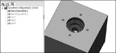
Make a dimension change for the MountRad dimension to 1 inch. The results to this point are shown in Figure 18.16.
Auto-create a design table by selecting Insert
Tip
Remember that to fill the first two columns up to Size5, you can make the two-by-two selection of the Size1 and Size2 entries in the first two columns, and pull down the handle in the lower-right corner of the selection box until the appropriate boxes are filled.
Manually fill in the C'Bore Dia values, but in cell D3, type the equation =C3/2+.25. Then use the same Fill technique to populate cells D3 to D7.
Test the configurations to make sure that they all work.
In the Design Library, browse to a folder where you would like to put this library feature. (Make sure that it is not used by assemblies or sheet metal forming tools.) Click a face created by the SpecialHole feature, and drag the feature into the lower pane of the Design Library. The Add to Library PropertyManager should appear on the left.
Although you selected a feature and dragged it into the library, the Items to Add field appears blank. Select the SpecialHole, tapped hole, and circular pattern features, either through the split FeatureManager or the flyout FeatureManager. Selecting the features from the graphics window does not work.
Position and zoom the view of the part so that when it is saved, you see a good preview of the library feature. Also, if you have not changed your background color from blue to white, this would be a good time to do so.
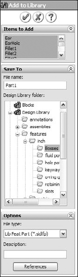
In the Save To pane, make sure that you select the correct folder, then fill in a filename, and click OK. Figure 18.18 shows the completed PropertyManager interface for this function.
Tip
You may notice that there are two library entries in the window. This is because an additional path has been added in Tools
If the new library feature does not appear in the Design Library, then click in the Design Library and press F5. If you do not like the way that it displays, then RMB click in a blank space inside the lower library window and select one of the other three options.
To edit the preview image of the feature, RMB click the feature in the Design Library window, select Open, reposition or zoom the view, and save it. Click in the Design Library and press F5 again.
Tip
It is recommended that when placing a library feature, you should close the original library feature window. The workflow proceeds much more smoothly if the part is closed before you use it.
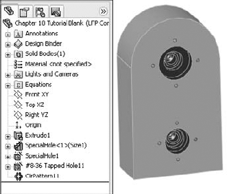
Open the part from the CD-ROM called Chapter 18 Tutorial Blank.sldprt. If you would like to examine the version of the SpecialHole part that I created, it is stored with this data as well.
Drag the SpecialHole library feature from the Design Library onto the face of the blank part. Place the feature near the squared-off end. Select a configuration from the list in the PropertyManager.
Tip
Although there is no prompt, when the Library Feature interface hesitates and there are configurations in the library feature, it is waiting for you to select a configuration. A prompt actually does exist, but it appears in the lower-left corner of the screen on the status bar in a tiny font, and most users probably do not notice it.
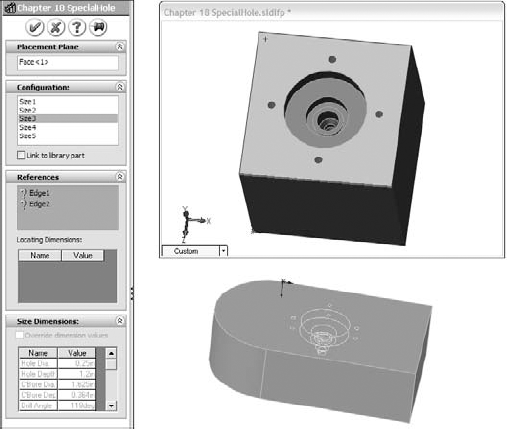
Try to orient the part in the same way that it appears in the preview window, as shown in Figure 18.19.
Select edges on the Blank part that correspond to the preview window. Click OK to accept the placement of the feature.
Double-click the SpecialHole feature and change the X and Y placement dimensions to place it one inch from the edges in both directions.
Note
You may remember from Chapter 10 that library feature configurations cannot be controlled by part configurations. In order to show different library feature configurations in different part configurations, you need to suppress one library feature and insert another. This is the best available workaround. It may be time to visit that enhancement request site again.
Place another library feature onto the blank part. Select a configuration, and click the green check mark icon, without selecting edges for the references.
Notice that the feature in the FeatureManager appears with an exclamation mark. If you investigate the cause of this, then you can see that the two dimensions that should be attached to edges are dangling because you did not select the references while placing the library feature. This was done on purpose to show a different technique.
Expand the library feature and the SpecialHole feature, and edit the first sketch in the Special Hole. This is the placement sketch. Delete the two dimensions that appear in dangling colors.
Add a concentric sketch relation between the placement point and the arc edge of the Blank part. Exit the sketch. The error message should now be gone and the hole should now be placed in the center of the arc.
RMB click the second library feature and select Dissolve Library Feature.
Note
When you dissolve a library feature, you lose any access to any configurations. Some users insist on dissolving every library feature, so that they can see regular features in the FeatureManager. This technique may also be useful if you would like to reorder some of the individual features within the library feature.
Figure 18.20 shows the finished part and FeatureManager. Good job!