
IN THIS CHAPTER
Understanding Smart Components
Using Smart Components
Making Smart Components
Tutorial: Working with Smart Components
Smart Components are one of the better design automation tools to come from SolidWorks in the last several releases. This is functionality that can save you a lot of time; the more standard items that you insert into your assemblies, the more time it can save you.
Smart Components are parts or assemblies that you can place into an upper-level assembly and that carry with them mounting features and hardware (cut-outs, mounting holes, and even fasteners). Smart Components are configurable, and can automatically size themselves on cylindrical parts.
A Smart Component can comprise several elements:
A single part or an assembly that may use size configurations
A configurable library feature that usually serves as mounting holes or a viewing window for the Smart Component
Associated hardware that may also be driven by sizes
A training assembly that is used to define the Smart Component
Some minor limitations exist, as you might expect:
A Smart Component part cannot have references that are external to the Smart Component group of which it is a member
When placed in the assembly, the associated library feature can only affect one component
The associated library feature is limited to one of several feature types:
Extruded or revolved cuts or bosses
Hole Wizard holes
Simple hole features
The setup time for Smart Components can be significant for the first one or two that you create, especially if you choose the auto-size option. The complexity of setup depends mainly on the number of configurations and configured parts that you use. The auto-sizing function takes the most time to set up because it requires matching configurations, and the auto-size table takes a while to manage, especially for multiple parts. Still, if you end up placing a given part with associated features and other components many times manually, this is a technique that can save you a lot of time.
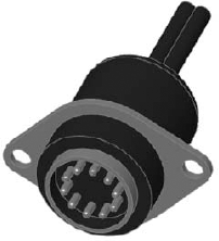
In this assembly, you first place the electrical connector part in the assembly, mate it in place, and then apply Smart Components. You can apply Smart Components by clicking the Smart Component icon that appears on the part in the graphics window when you select it. SolidWorks then prompts you to select the inside and outside faces of the sheet metal part (the hardware references the outside, and the cut-out feature references the inside). SolidWorks then creates the cut-out as an in-context feature that it places in the sheet metal part.
Tip
This in-context feature is why the Smart Component is limited to affecting a single part.
When you create the Smart Component, a new folder is added to the FeatureManager of the component. This folder contains all of the required information about the other elements, such as the in-context feature, any other parts that go with the Smart Component, the "training assembly" location, and the face references to locate everything. Figure 19.2 in the image to the left shows this folder in the connector part that is used in this example. The image to the right shows what is added to the assembly FeatureManager when you add a Smart Component. The only thing that existed in the design tree shown in Figure 19.2 before the Smart Component was the Test Box sheet metal part.
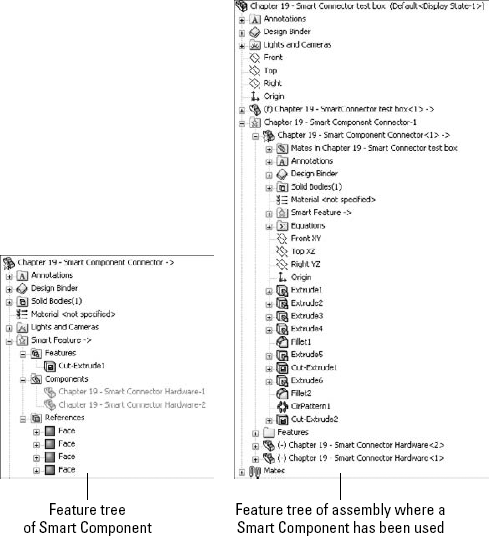
A star appears on the part symbol at the top of the FeatureManager, indicating that the part is a Smart Component.
You can place this Smart Component by following these steps:
Create an assembly, and add the target part to it. The target part is the one that the Smart Component will be mated to, and the one that will have the in-context cut-out inserted into it.
Warning
It is a good idea to save the assembly before you add the Smart Component to it. If the Smart Component is placed before the assembly is saved, the assembly has a tendency to forget that it has not been saved, and bumps the in-context feature to out-of-context when the name is changed from whatever the default name is (for example, Assem1.sldasm) to the name that you assign to it.
Put the Smart Component into the assembly. You can do this in the same way that you would add any normal part, including from the Design Library. If you use a part frequently enough to make it into a Smart Component, then you are probably going to want to have it in the Design Library for quick access. In fact, you can add a Smart Component to an assembly without using any of the Smart Component options.
Mate the Smart Component in the assembly. In this case, it was done with a face-to-face coincident mate and a pair of distance mates.
Next, apply Smart Components by clicking the Smart Component symbol on the part. If this symbol does not appear, then select the part in the FeatureManager. Figure 19.3 shows the Smart Component symbol on the part. If you have inserted many instances of a Smart Component, then each instance has the option to apply the Smart Component features and associated components.
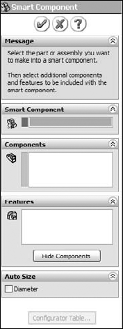
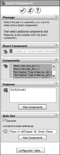
At this point, an interface similar to that of the Library Feature interface appears, with the small prompt window and a box for selecting references, as shown in Figure 19.4. After you select the references, and click the green check mark icon, the Smart Component, as well as the Smart Feature (in-context feature) and associated hardware components, are placed, and the job is done.

Auto-sizing is the ability of a Smart Component to select a size from a list of configurations, based on the size of geometry onto which it is being dropped. At this time, the only shape that can be auto-sized is the cylindrical shape.
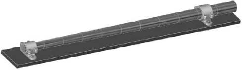
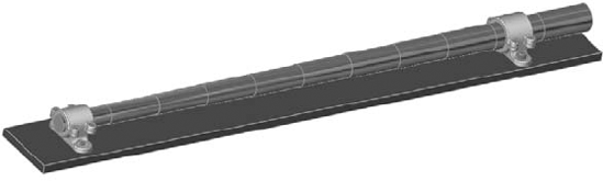
Figure 19.5 shows the effects of auto-sizing. Notice the two shaft holders. These are two instances of the same part, using different size configurations. When you drag the Smart Component over the small end of the stepped shaft, the configuration corresponding to that size appears. As you drag the part along the shaft and the shaft diameter increases, the next-larger Smart Component configuration appears. This is part of the functionality of Smart Components. Each configuration of the Smart Component is set up to fit onto a range of shaft diameters. If the diameter of the shaft is outside of the range or between sizes, then the Smart Component is not applied.
Sizes are governed by a configurator table, which looks similar to a design table, but works somewhat differently. The configurator table relates the configurations of the Smart Component to configurations of the individual components, which may also change size with the Smart Component. This serves as a subset of the function of a design table in an assembly, assigning part configurations to assembly configurations. Figure 19.6 shows a sample configurator table made for the following assembly.
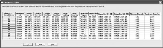
When you look at this table, you begin to understand why creating auto-sizing Smart Components is much more involved than in the previous example. The configurations of the Smart Component are listed to the left, and the individual part configs can be selected in each cell from a drop-down list of all available configs for that part. There is no way to set configs for multiple components at once, nor is there a copy-and-paste function. These shortcomings combine to make this format somewhat less user-friendly than an Excel-based design table.
Most notable are the Minimum and Maximum Diameter columns to the right. These columns supply the parameters that make the auto-size function work. While the range of sizes used here is too large for real-world design (+/– .050 inches), it serves to convey the idea. More importantly, SolidWorks understands that mating sizes are not always exactly equal, and the ability to use a range rather than exact values accommodates this very nicely, although it can be tedious to set up.
Another aspect of the setup shown here is that it uses Toolbox parts. If you want to use the auto-size functionality, then you need to be using configurations for Toolbox parts. You should pre-build all of the needed configurations, and ensure that the configurations are always available.
The most important point to remember about Smart Component setup is that you need to do it only once for each Smart Component. The second most important point is that the first setup is the most difficult. After that, subsequent setups become much easier to create. Adding components to the Smart Component is not so time-consuming unless the additional components are also configured and also auto-sized.
Smart Components must contain at least one associated component and one in-context feature, or have the configurator table filled out and functional. If you try to create a Smart Component from a standalone part, then nothing happens; the Smart Component interface simply closes. You may combine all three elements (associated component, in-context feature, and auto-size), but you must have at least one element.
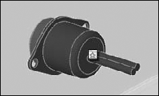
Because the electrical connector shown in Figure 19.1 has already been used to demonstrate the insertion of a Smart Component, it is used here to demonstrate how to create one.
All that you need to make a Smart Component with an associated Smart Feature (in this case, a cut-out and mounting holes) and mounting hardware (in this case, two stand-off screws) is the part itself. The part can even be an imported part (a Smart Component made from dumb geometry).
From the CD-ROM for Chapter 19, open the file named Chapter 19 – Connector Start.sldprt. This part is shown in Figure 19.7.
There is nothing special about this part. I modeled it in SolidWorks using standard features, and there are no configurations or special features. It represents an electrical connector that may be mounted in a sheet metal electrical enclosure.
The first step in setting it up is to create a mock assembly with a dummy part representing the sheet metal box. The part does not need to be complex or even sheet metal for that matter; it just needs to be close to the thickness that you would expect it to be mounted to. The assembly is called a training assembly, not because you are learning how to make a Smart Component, but because you are training the Smart Component to be smart.
Make a simple rectangular part, approximately 4 inches square and about .06 inches thick. Save the part to your hard drive. Give a name to the part so that it is clear that it belongs to this training assembly.
Place the rectangular dummy part into a new assembly, with a name that is both unique and identifiable.
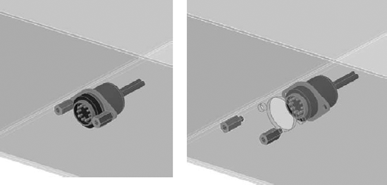
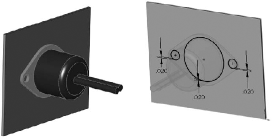
Put the connector into the assembly. Mate the part so that the flange is flush with the rectangular piece. Also use distance mates to locate the connector planes from the edges of the part, similar to Figure 19.8 in the image to the left.
Next, edit the dummy part in context, and offset edges of the connector part to extrude a cut, as shown in Figure 19.8 in the image to the right. Offset the two mounting holes and the area around where the connector will stick through the sheet metal by about .02 inches.
Exit Edit Component mode and add two instances of the part named Chapter 19 – Smart Connector Hardware.sldprt to the assembly. Mate the hardware part to the in-context hole, making sure that it goes to the outside thickness of the dummy sheet metal part.
Note
I have spent a fair amount of time trying to convince you that it is a best practice to avoid mating parts to in-context features, and yet here I tell you to do exactly that. Another thing I have tried to stress is that best practice suggestions are more like guidelines. If you are having performance problems with an assembly, then this may not be a great technique to use. However, sometimes there is a price to pay for sophisticated functionality, and if you think that your design can afford the price and will benefit from this functionality, then you should use it.

In the Smart Component selection box, select the connector part.
In the Components selection box, select the two hardware components.
In the Features selection box, select the in-context feature from the dummy part.
You are now finished setting up the Smart Component. Click the green check mark icon to accept the changes and exit out of the PropertyManager, and save the file.
The simple Smart Component took about 20 minutes to model and set up. That is not too bad for a feature that you will probably use a lot. The benefits are somewhat modest, placing three components and a feature.
However, when it comes to the auto-sizing example that is shown next, the benefits are more extensive. A total of seven individual parts are placed (including Toolbox parts)—three of which are automatically sized, depending on the geometry into which the Smart Component is dropped—and an in-context feature is added.
To begin, open the part from the CD-ROM named Chapter 19 - Clamp Start. Notice that this is a multibody part. There is no special knowledge that you need to have about multibody parts to complete this task. Multiple bodies are discussed in detail in Chapter 26.
With the Clamp Start part open, notice that several configurations already exist. If you click through the configurations or examine the design table in the part, you can see that various dimensions change. The primary dimension that changes is the diameter of the hole, and this change drives the diameter of, and distance between, the mounting holes.
Note
In SolidWorks 2007, you can only drive auto-sizing by cylindrical geometry.
Part of the Smart Component definition includes applying a Mate Reference to the part, so that the big hole automatically snaps to cylindrical geometry. Another aspect is that it adds in-context holes that match the mounting holes on the clamp. Figure 19.10 shows the assembly that this part is meant to go into. The clamp snaps onto the stepped shaft and adds holes to the plate.
Open the file named Chapter 19 Autosize Training Assembly.sldasm. This has been prepared to help you get started with the Smart Component training.
Note
The shaft is not necessary in the training assembly. The training assembly is intended to create the in-context Smart Feature and to create the configurator table. The shaft part has been added here for visualization only.
Insert the clamp part into the assembly, and mate it concentric to the shaft and coincident to the blue plate. It does not matter where the clamp sits along the shaft, but it should be fully mated into the location so that it does not slide back and forth.
Edit the plate in the context of the assembly, and convert entities from the mounting holes in the clamp to create holes in the plate that align with the holes in the clamp.
Exit the Edit Component mode.
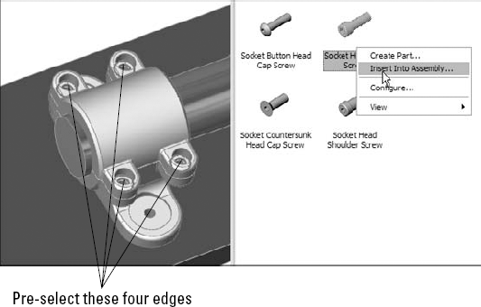
Activate Toolbox, select the four holes, as shown in Figure 19.11, and insert Socket Head Cap Screws, 3/8 by 24 by 5/8 inches. If you do not have Toolbox or choose not to use it, then a part with the correct name and sized configurations is provided on the CD-ROM.
Use the same fastener to place in the mounting holes, using the correct size for the hole. The length will be set later. Use a default length of 2.25 inches for both mounting holes.
Note
Working with the length of the fasteners is not a clean operation in Smart Components. The length is dependent on the thickness of the plate, which is not controlled by the Smart Fastener, nor can the Smart Fastener account for it, except through mates. (Remember that auto-sizing is driven only by a diameter.) Later in this chapter, you will see how the washers and nuts are put in place on the underside of the plate, but the screw length cannot be automatically calculated (unless the screw itself had an in-context relation to the nut).
Place washers and nuts on the screws on the backside of the plate.
This is where the process becomes a little convoluted. When the shaft diameter changes, the hole in the clamp changes to match (within the ranges that will be established). As the clamp becomes bigger, bigger screws are needed to secure the clamp and the holes grow further apart. Bigger screws mean additional configurations for the screw, washer, and nut parts. Remember that the configurations do not necessarily exist. I would not count on a Smart Component working if this meant that Toolbox had to create new configurations.
To create this example, I have pre-populated the Toolbox parts with all of the configurations needed for the range of sizes involved with this Smart Component. When you make your own Smart Components, you will have to do the same thing if you intend to use auto-sizing with Toolbox parts. The difficulty here is that the configurations include the diameter size of the screw as well as the length, which is unknown until you place the part.
All you have to worry about in this step is to make sure that the configurations are available and that the screws are placed properly.
Up to this step, you have just assembled the parts as if this were the only time you were going to do it. The automation of the process comes next. Figure 19.12 shows the training assembly to this point. The shaft and plate are shown in wireframe because they are external to the Smart Component.
This is the point in the previous example where the Make Smart Component command was used, and it is no different here. Click the Make Smart Component tool on the assembly toolbar.
Figure 19.13 shows the filled in Smart Component PropertyManager. Activate the Smart Component selection box and pick the clamp part.
In the Components selection box, select the six screw instances, the two washers, and the two nuts.
In the Features selection box, select the in-context feature or features that are associated with the Smart Component.
Note
Although the in-context feature can affect only a single part, this does not mean that you are limited to a single in-context feature. In most cases, only one feature is needed, but I am sure that there are situations where more than one would be useful. Also, remember that the in-context features are limited to extruded and revolved bosses and cuts, Hole Wizard holes, and simple hole features.
The configurator table is simply a table that enables you to select which component configurations are to be used with which Smart Component configuration. It looks and works very much like an assembly design table, but it is not Excel-based, and every cell must be set explicitly rather than using techniques for mass population or assigning properties to a range of configs, such as you can do with a real design table.
Each cell has a drop-down list of all of the available configurations for that component. If you have four instances of a single component, then you have to set each instance of each component.
Figure 19.14 shows the configurator table for this example.
Note
If the configurator table were to ever be as easy to use as, for example, an Excel design table, then Smart Component complexity could increase significantly. The configurator table could even ideally be created from an assembly design table. Instead of a single component with its associated hardware and mounting features, think of larger-scale sub-assembly attachments. This sort of work is possible now, but with configurator tables as cumbersome as they are, it is difficult to do more than a handful of parts.
Click OK. You are now done creating the auto-sizing Smart Component!


You may expect that with the training assembly, there is an extra burden of file management with Smart Components. This may seem counter-intuitive, but in fact, the only file that you need to worry about is the Smart Component itself.
This is not explained very well (or at all) in any of the documentation, but the Help and every reseller demonstration that I have seen on the topic all recommend that you simply delete the training assembly once you are done with it because it is not needed any more. This seems like saying that you should delete all of the mates in an assembly or the sketch relations in a part. How do you edit the Smart Component if you delete the assembly in which it is created?
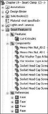
It turns out that all of the information to recreate the training assembly is stored in the Smart Component itself. This includes the in-context feature (which is stored as a library feature), and the locations of any associated components, as well as the configurator table. Figure 19.15 shows a part of the FeatureManager of a Smart Component. As you can see, the in-context feature, the associated components, and the face references are all listed there.
I was skeptical of this originally and had to test it thoroughly to ensure that deleting the training assembly would not cause any data to be lost, and so I can assure you that it works. Go ahead and delete the assembly.
Expanding somewhat on the discussion about whether or not to keep the training assembly file, here is a little exercise that you can try. Make a Smart Component by going through the preceding steps, by using the following tutorial, or by creating one of your own. Just make a simple one with perhaps one associated component and an in-context feature. Then go ahead and delete the training assembly.
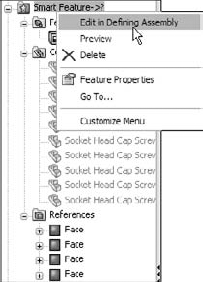
With the defining assembly gone, there appears to be no way to edit the setup of the Smart Component. RMB click the Smart Feature folder in the FeatureManager of the Smart Component, and select Edit in Defining Assembly, as shown in Figure 19.16. What happens next is that SolidWorks recreates the defining assembly from the data that is stored in the Smart Component. This assembly is saved in a system temp folder using the name <Smart Component name>_ta.sldasm. If the Smart Component uses an in-context feature, it is saved to the temp directory as a library feature file using the name of the dummy part, and appending "_lf" to the filename, for example, Dummy_lf.sldlfp.
The Edit Definition button appears in the upper-right corner of the graphics window. If you click this button, the Smart Component PropertyManager interface appears again, enabling you to change the selection of associated components and in-context features, to change the auto-size setting, or to edit the configurator table.
Thus, all of the settings are preserved, and the training assembly exists only as a phantom in a temp directory. Although this appears to be counter-intuitive, it works.
This tutorial guides you through creating a Smart Component that only uses the auto-sizing feature. This enables you to manually create parts that snap to size like Toolbox parts, but without using Toolbox functionality. Follow these steps:
Open the part from the CD-ROM that has the filename Chapter 19 – Tutorial Start.sldprt. This part originally came from Toolbox, and already contains a few configurations.
Make an assembly that contains only this part.
Make the part into a Smart Component, and turn on the option to auto-size.
Select the small diameter of the part as the concentric mate reference. Figure 19.17 shows the selection.
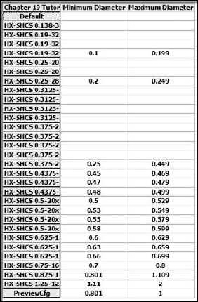
Click the Configurator Table button, and fill the table in so that it looks like Figure 19.18. Some configurations are blank. This is because only the rows that have minimum and maximum values are used by the auto-size function. The rest are overlooked.
Close the configurator table, and save the assembly.
Exit the assembly and, in the part file, save it to a folder in your Design Library. If you do not know where your Design Library is located, then select Tools

Display the part in the Design Library panel of the Task pane.
Open the part from the CD-ROM with the filename Chapter 19 Tutorial Plate.sldprt. Place this part into a new assembly.
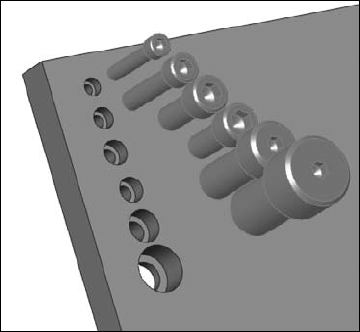
Drag the Tutorial Start (Smart Component) from the Design Library into the assembly, and move the part over the holes in the plate. As you drag the part up and down the row of holes, the part changes sizes to match each hole. Figure 19.19 shows all of the holes that are populated with the matching Smart Component sizes, as driven by the configurator table.
To edit the configurator table, open the Smart Component part in its own window. Then RMB click the Smart Feature folder and select Open In Defining Assembly.
An assembly opens that was created from the data stored in the part. Click the Edit Definition button that appears in the upper-right corner of the graphics window.
Reassign the minimum and maximum diameter values for the 3/16-inch and 1/4-inch configurations to the shortest lengths. For example, the chart shows the 3/16-32x.75-inch configuration to be assigned to a minimum of .1 and a maximum of .199. Move the .1 and .199 values up two cells to the 3/16-32×1/4-inch configuration. Do something similar for the 1/4-28×1-inch configuration. The edited part of the chart now looks like Figure 19.20.


Tip
You may have difficulty expanding the width of the column that contains the configuration names, thus making it difficult or impossible to read the ends of the long config names. However, like Excel, you can expand the height of the rows, which causes the config names to wrap, as shown in Figure 19.20.
Smart Components can automate the placement of a main component, as well as associated mounting features and components. It can also offer automatic resizing options, depending on the geometry to which they are mated. The setup for Smart Components varies from simple to complex, with auto-sizing causing most of the complexity.