
IN THIS CHAPTER
Understanding feature-based Modeling
Understanding history-based Modeling
Sketching with parametrics
Understanding Design Intent
Editing Design Intent
Working with associativity
Let's face it; people develop brand loyalty to CAD software programs. It sounds silly, but you know it's true. If you are coming to SolidWorks from another CAD program, you are probably feeling a level of unease that is proportional to the amount of time you spent using the other program. You will get past that, and everything will be fine, I promise. As you will see, SolidWorks does everything as well as, or better than, your old software, and you will never crave your old software after you drink this Kool-Aid.
The biggest hurdle that many users face in learning a new CAD program is letting go of the old one. In some cases, the old software helps you to understand the new one, but in others, the thinking is just too different, and you may need to forget everything you thought you knew about CAD.
Switching to SolidWorks can involve a little of both. For example, if you are coming from Inventor, Solid Edge, or another program in that class, you will find SolidWorks to be very familiar territory, with a similar if not identical design philosophy. SolidWorks also shares a lot of underlying structure with Pro/ENGINEER, and if you are coming from that product, there will be some relearning, but much of your training will be transferable.
If you are coming from 2D AutoCAD, SolidWorks may at first cause a bit of culture shock for you. However, after you accept the concept that getting the model correct is dependent on the process, things will go more easily. As you will see, SolidWorks, and in fact most solid modeling in general, is very process-based.
SolidWorks is also a very Windows-based software, and so if you are familiar with Windows conventions, then you already know a lot about the SolidWorks interface and shortcuts. The regular and context-sensitive menus, toolbars, and keyboard shortcuts, as well as many other interface elements, all work the same as they do in Word, Excel, or PowerPoint. OS X and Linux users should not hold their breath for SolidWorks to be ported to those operating systems, although there have been third-party developments that allow Windows software to run on other operating systems and hardware.
In any case, regardless of how you arrived here with this SolidWorks Bible in your hand, here you are. Together we will progress from basic concepts to advanced techniques, everyday settings, and subtle nuances. This book will serve as your friend, tutor, and desk reference for learning about SolidWorks software.
There is some terminology that you need to come to grips with before we dive into building models with SolidWorks. Notice that I talk about "modeling" rather than "drawing." This is because SolidWorks is really virtual prototyping software. Whether you are building an assembly line for automotive parts or designing decorative perfume bottles, SolidWorks can help you visualize your product in the most realistic way possible without actually having it in your hand. This is more akin to making a physical model in the shop than drawing on paper.
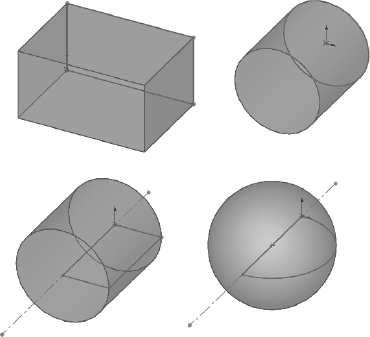
"Feature-based" modeling means that you build the model by incrementally identifying functional shapes, and applying processes to create the shapes. For example, you can create a simple box by using the Extrude process, and you can create a sphere by using the Revolve process. However, you can make a cylinder by using either process, by revolving a rectangle or extruding a circle. You start by visualizing the 3D shape, and then apply a process to a 2D sketch to create that shape. This concept on its own is half of what you need to know to create models with SolidWorks.
Figure 1.1 shows images of simple feature types with the 2D sketches from which they were created.
Many different feature types in SolidWorks enable you to create everything from the simplest geometry shown above to free-form shapes. In general, when I talk about modeling, I am talking about solid modeling, although SolidWorks also has a complete complement of surfacing tools. I will discuss the distinction between solid and surface modeling in a later chapter.
Table 1.1 lists some of the most common features that are found in SolidWorks, and classifies them according to whether they always require a sketch, a sketch is optional, or they never require a sketch.
Table 1.1. Feature Types
Sketch Required | Sketch Optional | No Sketch (Applied Features) |
|---|---|---|
Extrude | Loft | Fillet |
Revolve | Sweep | Chamfer |
Rib | Dome | Draft |
Hole Wizard | Shape | Shell |
Wrap | Deform | Flex |
While the bulk of this book focuses on the use of solid features, I believe that no set of modeling tools is complete without surface-modeling functions. Hybrid features combine the use of solids and surfaces in some way, and are discussed in more detail in Chapter 27. The surfacing and hybrid features available in SolidWorks are:
Lofted surface
Swept surface
Fill surface
Boundary surface
Freeform surface
Offset surface
Knit surface
Radiate surface
Ruled surface
Replace Face
Trim surface
Untrim surface
Cut with surface
Thicken surface
Cut Thicken surface
In addition to these features, there are many other types that create reference geometry (such as curves, planes, and axes), or perform some operation on existing geometry.
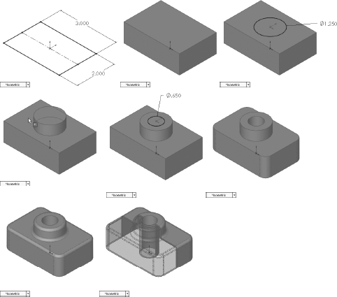
In addition to being feature-based, SolidWorks is also history-based. To indicate process history, there is a panel to the left side of the SolidWorks window called the FeatureManager design tree. The FeatureManager keeps a list of the features in the order in which you have added them. It also enables you to reorder items in the tree (in effect, to change history). As a result, the order in which you perform operations is important. For example, consider Figure 1.2. This model was created by the following process:
Create a sketch.
Extrude the sketch.
Create a second sketch.
Extrude the second sketch.
Create a third sketch.
Extrude Cut the third sketch.
Apply fillets.
Shell the model.
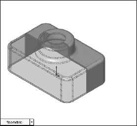
If the order of operations used in the above part were slightly reordered, the resulting part would also look slightly different, as shown in Figure 1.3.
Figure 1.4 shows a comparison of the FeatureManager design trees for the two different feature orders. You can reorder features by dragging them up or down the tree. Relationships between features can prevent reordering; for example, the fillets are dependent on the second extruded feature, and cannot be reordered before it. This is referred to as a Parent/Child relationship.
Note
Reordering and Parent/Child relationships are discussed in more detail in Chapter 11.

Note
The part used for this example is available in the material from the CD-ROM, named Chapter 1 – Features.SLDPRT.
The order of operations, or history, is important to the final state of the part. For example, if you change the order so that the shell comes before the extruded cut, the geometry of the model changes, creating a sleeve inside instead of just a hole on top. You can try this for yourself by opening the part indicated above, dragging the Shell1 feature in the FeatureManager, and dropping it just above the Cut-Extrude1 feature.
In some cases, reordering the features in the FeatureManager may result in geometry that might not make any sense; for example, if the fillets are applied after the shell, they might break through to the inside of the part. In these cases, SolidWorks gives an error that helps you to fix the problem.
In 2D CAD programs where you are just drawing lines, the order in which you draw the lines does not matter, because the results are the same. This is one of the fundamental differences between history-based modeling and non-history-based drawing.
Features are really just like steps in building a part; the steps can either add material or remove it. However, when you make a part on a mill or lathe, you are only removing material. The FeatureManager is like an instruction sheet to build the part. When you reorder and revise history, you change the final result.
You have already seen that sketching is the foundation that underlies the most common feature types. We will now find that sketching in parametric software is vastly different from drawing lines in 2D CAD.
Dictionary.com defines the word parameter as "one of a set of measurable factors ... that define a system and determine its behavior and [that] are varied in an experiment." What this means to us as SolidWorks users in a practical sense is that we can create sketches that change according to certain rules, and maintain relationships through those changes. This is the basis of parametric design. It extends beyond sketching to curve elements, surface features, and solid features.
SolidWorks makes 2D and 3D sketching possible. Of the two methods, 2D sketches are by far the more widely used. You create 2D sketches on a selected plane, planar solid or surface face, and use them to establish shapes for features such as Extrude, Revolve, and others. Relations in 2D sketches are often created between sketch entities and other entities that may or may not be in the sketch plane. In situations where other entities are not in the sketch plane, the out-of-plane entity is projected into the sketch plane in a direction that is normal to the sketch plane. This does not happen for 3D sketches.
You use 3D sketches for the Hole Wizard, piping, wiring, and weldments, among other applications such as complex shape creation.
Both 2D and 3D sketches share some relation types, although some of these relations work differently in the two types of sketches. Some relations that are unique to each type of sketch. The available sketch relations are:
Along X, Along Y, Along Z: 3D sketch only. Along X means that the Y and Z coordinates do not change—only the X coordinates. This is similar for the other relations.
Intersection: 2D and 3D sketches. This relation is created by the Intersection Curve sketch tool. You cannot apply it manually.
Coincident: 2D and 3D sketches. In a 2D sketch, a point can be coincident with an entity that is not on the sketch plane because SolidWorks considers the external entity to be projected into the sketch plane. In a 3D sketch, the coincident relation is explicit rather than projected.
Concentric: 2D and 3D sketches. Available between arcs, circles, and ellipses, as well as items that project into a 2D sketch plane as arcs, circles, or ellipses.
Coradial: 2D and 3D sketches. This applies to arcs or circles that have the same center and radius.
Collinear: 2D and 3D sketches. Only available between a linear sketch entity and another linear sketch, edge, or curve entity.
Equal: 2D and 3D sketches. This is used to make lines of equal length or arcs and circles of equal radius.
Equal Curvature: 2D and 3D sketches. This relation only applies to splines, although you can apply it between a spline and other sketch entities, edges, or curves. This is similar to Tangent, except that in addition to being tangent, the spline also matches the curvature of the other item at the end of the spline. The curvature value cannot be set explicitly for any sketch entity except in the form of an arc or circle radius. Curvature = 1/radius.
Fix: 2D and 3D sketches. This clamps a sketch entity wherever it is when you apply the relation. It is not considered best practice to make extensive use of the Fix relation. When it is used, it is a frequent cause of overdefined sketches and troubleshooting difficulties.
Horizontal: 2D and 3D sketches. Horizontal and vertical relations are relative to the local sketch origin, not the global part origin. When used in a 2D sketch, Horizontal is indicated by the short leg of the red sketch origin. When used in a 3D sketch, Horizontal can be applied only when sketching on a plane within the 3D sketch, and it has no relation to geometry outside the plane.
Midpoint: 2D and 3D sketches. An endpoint, sketch point, or centerpoint may be placed at the midpoint of a line or arc. In 3D sketches, only a line can receive a midpoint relation.
On Edge: 2D and 3D sketches. This relation is created by the Convert Entities sketch tool. You cannot apply it manually.
Parallel: 2D and 3D sketches. This may be used between sketch lines and linear edges, as well as curves or other sketch lines. When applied in a 2D sketch between a sketch line and an out-of-plane entity, the out-of-plane entity must project into the sketch plane as a straight line, and the parallel will apply to the projection.
Pierce: 2D sketch only. A sketch point, centerpoint, or endpoint can be pierced by an edge, curve, or sketch that is external to the sketch and out-of-plane. The point where the out-of-plane curve goes through the sketch plane is the pierce point. The out-of-plane entity is not projected into the sketch plane. It is the only 2D sketch relation that does not use projected out-of-plane entities. If the curve entity does not cross the sketch plane, the relation fails. If the curve crosses the sketch plane at more than one location, the pierce point becomes the closest crossing to the selected sketch point.
Symmetric: 2D sketch only. Symmetric relations are created by mirroring items around a sketch centerline, and you can also apply them manually to pre-existing sketch entities, by using a centerline for reference.
Tangent: 2D and 3D sketches.
Vertical: 2D and 3D sketches. Horizontal and vertical relations are relative to the local sketch origin, not the global part origin. When used in a 2D sketch, Vertical is indicated by the long leg of the red sketch origin. For planes in 3D sketches, horizontal and vertical relate only to the local plane, not to the 3D sketch origin. As a result, if a line is constrained to a plane in a 3D sketch, the plane is still allowed to rotate unless there is sketch geometry constrained to geometry outside of the sketch.
On Surface: 3D sketch only. Planar sketch entities such as lines and arcs in a 3D sketch can be given the On Surface relation to planes or planar faces. Sketch points can be given the relation to any surface type. The On Surface constraint is created automatically by the Spline On Surface sketch tool.
At Intersection Of Two Faces: 2D and 3D sketches. This sketch relation is only created by the Intersection Curve sketch tool, which draws sketch entities where surfaces, solid faces, or planes intersect. This relation cannot be created manually.
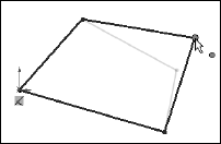
For a simple example of working with sketch relations in a 2D sketch, consider the sketch that is shown in Figure 1.5. The only relationships between the four lines are that they form a closed loop that is touching end to end, and one of the corners is coincident to the part origin. The small square icon near the origin is the symbol for a coincident sketch relation. The setting to enable or disable these sketch relation symbols is found at View

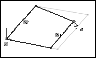
If you drag any of the unconstrained corners (except for the corner that is coincident to the origin), the two neighboring lines will follow the dragged endpoint, as shown in Figure 1.6. Notice the ghosted image left by the original position of the sketch. This is helpful when experimenting with changes to the sketch because you can see both the new and the old states of the sketch. The setting to enable or disable this ghosted position is found at Tools
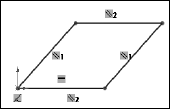
If you add a parallel relation between opposing lines, they now act differently, as shown in Figure 1.7.
Next, a second parallel and a horizontal relation are added, as shown in Figure 1.8. If you are following along by recreating the sketch on your computer, you will notice that one line has turned from blue to black.
The colors represent sketch states. Sketch states include Underdefined, Overdefined, Fully Defined, Unsolvable, Zero Length, and Dangling. There can be entities with different states within a single sketch. Also, endpoints of lines can have a different state than the rest of the sketched entity. For example, a line that is sketched horizontally from the origin has a coincident at one endpoint to the origin, and the line itself is horizontal. As a result, the line and first endpoint are black, but the other endpoint is underdefined because the length of the line is not defined. Sketch states are indicated in the lower-right corner of the graphics window and also in the status bar.
Blue: Underdefined. The sketch entity is not completely defined. You can drag it to change size, position, or orientation.
Black: Fully Defined. The sketch entity is fully defined by a combination of sketch relations and dimensions. A sketch cannot be fully defined without being connected in some way to something external to the sketch, such as the part origin or an edge. Multiple external entities may be used, as appropriate. (The exception to this rule is the use of the Fix constraint, which, although effective, is not a recommended practice.)
Red: Overdefined. This can mean a number of things, but it is usually caused by conflicting relations or dimensions. For example, if a line has both horizontal and vertical relations, it becomes overdefined because one of the relations is satisfied, while the other is not.
Pink: Unsolvable. The difference between pink and red is that red is in one of several possible correct locations, whereas pink is not able to move to a correct location, generally because of another red entity.
Yellow: Zero Length. Solving the sketch relations would result in a zero-length entity; for example, this can occur where an arc is tangent to a line, and the centerpoint of the arc is also coincident to the line.
Brown: Dangling. The relation has lost track of the entity to which it was connected.
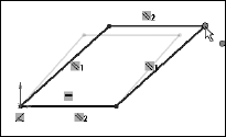
Now you can see that dragging one corner only allows the lines to move in certain ways, as shown in Figure 1.9.
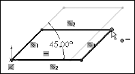
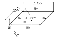
Dimensions are also part of the parametric scheme. If you apply an angle dimension about the origin and try dragging again, as shown in Figure 1.10, you see that the only aspect that is not locked down is the length of the sides. Notice also that when the angle dimension is added, another line turns black.
Finally, adding length dimensions for the unequal sides completes the definition of the sketch, as shown in Figure 1.11. At this point, all lines have turned black. This is the state that we call "fully defined." Between the dimensions and sketch relations, there is enough information to recreate this sketch exactly.
Note
It is considered best practice to fully define all sketches. However, there are times when this is not practical. When you create freeform shapes, generally through the use of splines, these shapes cannot easily be fully defined, and even if they are fully defined, the extra dimensions are usually meaningless, because it is impractical to dimension splines on manufacturing drawings.
It is the idea of reacting to change that most concerns us regarding parametric design. There are other factors that can also drive the sketch, such as equations, other model geometry that is external to the sketch, and even geometry from another part in an assembly, as you shall see later.
"Design Intent" is a phrase that you will hear SolidWorks users say a lot. I like to think of it as "design for change." Design Intent means that when you put the parametric sketch relations together with the feature intelligence, you can build models that react to change in predictable ways.
An example of Design Intent could be a statement in words that describes general aspects that help define the design of a part, such as "This part is symmetrical, with holes that line up with Part A, and thick enough to be flush with Part B." From this description, and the surrounding parts, it is possible to recreate the part in such a way that if Part A or Part B changes, the part being described updates to match.
There are some types of changes that cause features to fail or sketch relations to conflict. In most situations, SolidWorks has ample tools for troubleshooting and editing that allow you to either repair or change the model. In these situations, it is often the Design Intent itself that is changing.
Note
When editing or repairing relations, it is considered best practice to edit rather than delete. Deleting often causes additional problems further down the tree. Many users find it tempting to simply delete anything that has an error on it, but the cause of the error may be something other than what is identified.
Design Intent is generally thought of as a static concept that controls changing geometry. However, this is not always the way things are. Design Intent often changes, thus requiring the way in which the model reacts to geometric changes to also change. Fortunately, SolidWorks has many tools to help you deal with situations like this.
One of the most obvious tools necessary for visualizing existing Design Intent is to be able to see the sketch relations. You can show or hide icons that represent the relations using the menu selection View, Sketch Relations.
Tip
View, Sketch Relations is an excellent candidate for use with a hotkey, thus allowing you to easily toggle the display on and off.
Note
For more information on creating and managing hotkeys, see Chapter 2.
You can use the sketch relation icons that are visible on the screen to delete relations by selecting the icon and pressing Delete on the keyboard. You can also use them to quickly tell the status of sketch relations, applying referring to the colors defined earlier.
You can find the Display/Delete Relations tool on the Sketch toolbar or by selecting a sketch entity in an open sketch. The sketch status colors that were defined earlier also apply here, with the relations being shown in the appropriate color. (Relations are not shown in blue or black, only the colors that cause errors, such as red, yellow, pink, and brown.) This tool also allows you to group relations by several categories:
All in This Sketch
Dangling
Overdefining/Not Solved
External
Defined in Context
Locked
Broken
Selected Entities
In the lower Entities panel, you can also replace one entity with another, or repair dangling relations.
Suppressing a sketch relation means that the relation is turned off and not used to compute the position of sketch entities. Suppressed relations are generally used in conjunction with configurations.
Note
Configurations are dealt with in detail in Chapter 10.
Associativity in SolidWorks refers to links between documents, such as a part that has an associative link to a drawing. If the part changes, the drawing updates as well. Bi-directional associativity means that the part can actually be changed from the drawing. One of the implications of this is that you do not edit a SolidWorks drawing by simply moving lines on the drawing; you must change the model, which causes all views of the part or assembly to update correctly.
Other associative links include using base parts, where one part is inserted as the first feature in another part. This might be the case when you build a casting. If the part is designed in its "as cast" state, it is then inserted into another part where machining operations are performed by cut features and the part is transformed into its "as machined" state. This technique is also used for plastic parts where a single shape spans multiple plastic pieces. A "master part" is created and split into multiple parts that could, for example, become a mouse cover and buttons.
One of the most important aspects of associativity is file management. Associated files are kept connected by filenames. If a document name is changed, and one of the associated files does not know about the change, then the association between the files can become broken. For this reason, you should use SolidWorks Explorer to change names of associated files. There are other techniques that work, as well as some techniques that you should avoid.
Note
It is considered poor practice to change filenames of documents that are referenced by other documents with Windows Explorer. Links between parts, assemblies, and drawings can be broken in this way. Using SolidWorks Explorer or a Product Data Management, or PDM, application is the preferred method for changing filenames.
Product development is about design, but it is even more about change. You actually design something once, but you may modify it endlessly (or it may seem that way sometimes). Similarly, SolidWorks is about design, but it really enables change. Think of SolidWorks as virtual prototyping software that allows you to change your prototype rather than having to make a new one. Virtual prototypes will never completely replace physical models, but they may reduce your dependence on them to some extent.
SolidWorks is also about reusing data. Associativity allows you to model a part once and use it for Finite Element Analysis, or FEA, creating 2D drawings, building assemblies, creating photorealistic renderings, and so on. When you make changes to the model, your drawing is already updated, and you don't have to reapply FEA materials and conditions or redo the rendering setup. Associativity saves you time by reusing your data. Associativity and change driven by feature-based and history-based modeling can take some getting used to if you have had limited exposure to it, but with some practice it becomes intuitive and you will see the many benefits for enabling change. Parametric sketching and feature creation help you to maintain Design Intent and also adjust it as necessary.