
Consider the cigar box and decide how to best orient your switches. Although you could use plain old light switches for this project—they’re cheap, and very easy to scrounge—it is much easier to drill a hole than to cut a slot. The switches listed in the supplies are reasonably priced—around $5.50 for all three—include nifty metal ON/OFF labels, make a satisfying clack, and have easy-to-install 1/2″ round shafts. If you decide to go with wall switches, you can use the inner rectangle of an old switch cover plate as a stencil, then cut your slots using a keyhole saw or jigsaw.
Drill holes for the switches; you’ll want to leave a little space around each switch (so you have room to run the wires later) and be sure that the box will still close nicely once your switch is installed. Cigar boxes are made of thin, cheap, fine-grained wood and shouldn’t splinter too badly if you run the drill fast and put a little weight behind it.
Temporarily mount the switches and use them as a reference as you choose positions for the LEDs. A 3/16″ hole, which is what you see perforating the box’s lid in Figure 2-3, will hold a standard LED quite snugly. Drill one extra hole so that the buzzer won’t be terribly muffled.
You’ll ultimately want to prevent unauthorized toddler access to the interior; the pair of brass screws will accomplish this. Cut two 3/4″ blocks and glue them to the inside front corners of the box (see Figure 2-4 for orientation). Let the glue fully set (usually overnight), then close the box and drill guide holes a touch slimmer than the body of your screws (you’ll probably end up using a 7/64″ or 1/8″ bit).
While you’re waiting for the glue to dry, solder together the LED arrays illustrated in Figure 2-5. The triangle with two arrows shooting out of it represents a light-emitting diode (LED), and the jagged line a resistor (there’s a component symbol cheat sheet in the appendix). LEDs have two characteristics, apart from emitting light: They only allow current to pass through them in one direction (i.e., they have polarity), and they only do so if the current exceeds some minimum voltage, called the forward voltage. For most orange or red LEDs, the forward voltage is around 2 volts, hence the two AA batteries (totaling around 3 volts) powering this project.
As a rule, never attach a battery directly to an LED. The LED will quickly become overwhelmed, often getting hot enough to burn you before snuffing out with an audible pop. In this design, a 47 ohm resistor limits the current going into the LED. (There’s some nifty math behind this; see Voltage, Current, and Resistance in Voltage, Current, and Resistance if you want to try using different colored LEDs or a different battery.) Figure 2-6 is a photo of the three light circuits. To make the first circuit, just solder a 47 ohm resistor to the positive leg of one of the LEDs (the positive leg is usually longer; the negative leg is always marked by a flattened or notched edge on the LED’s lens). On schematics, the negative leg of the LED always coincides with the black line on the LED symbol.
The second circuit adds a second LED connected in parallel with the first (by contrast, the resistor in the first schematic is in series with its LED). Construct the second circuit, using black wire to connect the negative legs and red for the positive (color-coding is optional but makes it easier to keep your wires uncrossed later).
The third circuit adds one more LED in parallel. Make two of these arrays.
If the LEDs were connected in series, then the forward voltage would add up and be around 4 volts after just two LEDs, exceeding the power our little pair of AAs could furnish. By wiring them in parallel, you can keep the voltage lower and buffer each array with a single resistor.
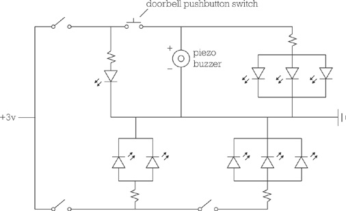
Wire up the switches. The schematic in Figure 2-7 shows how the switches are inserted into the circuits and the arrays wired together. You’ll want to run relatively long wires—probably 5″ or 6″, depending on the dimensions of your cigar box—to and from the switches and battery pack to give you plenty of room to work when you install the wiring in the box in Step 7.
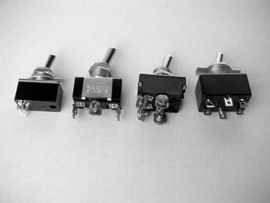
Your switches may have screw terminals, like the middle two switches in Figure 2-8, or may have solder lugs (flat tabs that you solder the wires to, like the other two switches); all work fine for the Switchbox. The three-switch pack from RadioShack comes with two SPST switches and one DPDT switch; just wire the DPDT up as though it were SPST, using one central and one end terminal along the same edge.


Types of Switches
This design calls for single pole single throw (SPST) toggle switches, which are the kind you are most familiar with: A single circuit is completed by a single throw of the switch (a standard bedroom light switch is an SPST switch). Other common toggle-switch configurations are:
single pole dual throw (SPDT)—flick the switch one way to complete, or close, one circuit, and the other way to turn off, or open, the first circuit and complete a different circuit
dual pole single throw (DPST)—throw the switch to close two separate circuits simultaneously
dual pole dual throw (DPDT)—throw it one way to turn on two circuits and the other way to turn off the first two and turn on two more circuits
Figure 2-8 shows all four common varieties of toggle switch.
A few notes: The switches always break the positive lead, which means that they should have red wires connected to both terminals; one terminal is connected to the red lead from an LED array, and the other terminal connected to the red lead from the battery pack. All of the black wires get connected and go to the negative terminal of the battery pack, which is represented on the schematic by the triangle composed of three parallel lines (on the far right of the circuit diagram). This symbol technically means ground; for all of the projects in this book, that’s synonymous with the negative terminal on the power pack. The piezo buzzer, much like an LED, is polarized; its black (i.e., negative) lead connects to the black wire on the battery pack, and its positive lead (the red one) goes to one of the doorbell switch’s two terminals. The other doorbell switch terminal is connected to the red wire from the battery pack. (Despite what’s implied by Figure 2-9, you’ll probably have to mount the doorbell switch in the top of the box before hooking it up.)
The schematic (Figure 2-7) is orderly and clear; contrast that to the tangle of wires and switches pictured in Figure 2-9. This is why the good Lord saw fit to create the circuit diagram (on the fifth day, after marine mammals but before birds). God bless the circuit diagram.

Mount everything in the box as in Figure 2-10. The LEDs will probably be held snugly enough by the holes, but you can always smear their edges with a little CA (cyanoacrylate adhesive) before inserting them. Since you don’t want clever little hands uninstalling the switches (and possibly eating a nut in the process), smear a little CA on the threads of each switch’s collar, then tighten the nut down firmly. Clean your hands and tools, and let the glue set overnight; no one will be removing these nuts without tools and good manual dexterity. Glue the buzzer to the inside of the box. Securing the battery pack using Velcro, rather than glue, will make it considerably easier to change the batteries in the future.
Tuck in the wires, close up the box, and drive the brass screws home, sealing the Switchbox shut.
