Look at the schematic in Figure 15-3. We’re going to start by building the optoisolator (located at the bottom of the schematic in the little dashed rectangle). In the old Fender amps, this unit was called a vibrato bug.
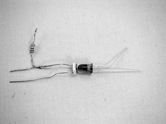
Solder a 470 ohm resistor (yellow-purple-brown) to the base of one leg of the photoresistor. Then, place the photoresistor and one LED snout-to-snout. Cock out the negative leg of the LED (that is the one marked by the flattened side of the LED lens; see Figure 15-4) so that you’ll recognize it later. Now wrap these two together with a strip of duct tape, sealing out as much light as possible.
Now you’ll prepare the external hardware: Both jacks, the small SPST switch, the DPDT switch, the 100k variable resistor, and the remaining LED (which is the indicator LED) will ultimately be mounted on the enclosure.
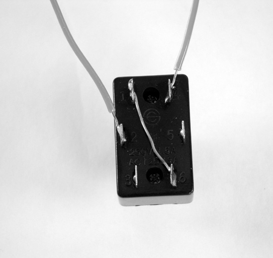
Look at the bottom of the DPDT switch, holding it so that the six lugs are in two vertical rows. These are (from top to bottom) 1, 2, and 3 along the left, and 4, 5, and 6 along the right. Cut a short length of bare bus wire, and solder it between 1 and 6 (i.e., the upper-left and lower-right lugs; see Figure 15-5). Cut two lengths of insulated wire, strip them, and solder them to lugs 2 and 4 on the DPDT (the middle-left and top-right lugs; see Figure 15-5).
Figure 15-5. The prepared DPDT switch. The insulated wire on the left is the effect send and the insulated wire on the right is the effect return. The audio input will ultimately be connected to lug 1 (which is shorted diagonally to lug 6), the audio output to lug 5, and lug 3 to ground.
Measure seven more lengths of insulated wire, strip them, and solder one to each tip lug on each jack, one to each leg of the indicator LED, one each to lugs 1 and 2 of the 100k potentiometer (if you’re having trouble telling jack and pot lugs apart, flip to the appendix), and one to one of the two lugs on the SPST switch. Finally, solder the red battery lead to the other lug of the SPST switch. All of this wired-up hardware is shown in Figure 15-6.
The printed circuit board (PCB) we’re using in this project is great for single-IC projects like this, because it gives us lots of room to bring multiple connections to each pin. Unfortunately, it can also be a bit confusing when viewed from the top (as you’ll soon learn). Figure 15-7 shows the solder pads on the bottom of this board; hopefully, the PCB’s utility is self-evident. As long as you follow the instructions and figures carefully, double-checking your work as you go, you’ll be fine, even if this is your first soldering project.
Note
Keep in mind that it’s best to use an IC socket and to solder with the socket empty, even though the illustrations show the chip in place.
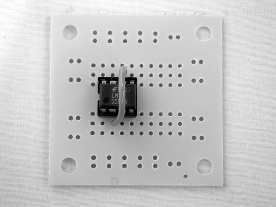
Mount the IC socket for the 555 timer on the circuit board. Snip a 2″ length of insulated wire, fly it over the top of the chip from pin 2 to pin 6, and then solder it into place. As always, remember that pins are numbered counterclockwise, beginning with the lower-left pin; see the appendix for details. Note that, in Figure 15-8, we’ve offset the chip by one column of holes to the right; this is so we can use the left and right edges of the PCB for grounds.
If you are confident of your skills, you could solder this with the chip in place and use a short length of bare bus wire to connect pins 2 and 6, snugging it over the top of the IC.
Solder the positive leg (the stripe-less one) of the 1.5 μF capacitor to pin 6, and run the other leg to the left-edge ground. Solder a 120k resistor (brown-red-yellow—it’s the one crammed in the upper-left corner of the PCB shown in Figure 15-9) between pins 7 and 8, and one end of the 22k resistor (red-red-orange) to pin 7 (leave the other end pointing up in the air for now). Finally, solder a 470 ohm resistor (yellow-purple-brown) to pin 3 (likewise leaving its other leg hanging).
Mount the optoisolator to the circuit board with the optoisolator’s LED side toward the top of the PCB and its resistor side toward the bottom. Solder lug 4 of the DPDT switch (the upper right) to the output leg of the photoresistor (the one with the resistor hanging off of it) and the remaining insulated wire on the DPDT switch (lug 2) to the input leg, which is the only leg left on the photoresistor side of the optoisolator. (Don’t worry about the dangling resistor—you’ll solder that to the ground later.) In Figure 15-10, our optoisolator is straddling the middle of the PCB, just like the IC socket. The wire running from the PCB to the bottom of the picture is the effect send (connected to lug 2 of the DPDT switch, it brings the signal from your instrument into the effect via the input jack). The insulated wire to its right is the effect return, going to lug 4 of the switch, which sends the effected signal to the output jack (and presumably to your amplifier or other effects).
Slip the 470 ohm resistor connected to pin 3 under the optoisolator (as noted in the caption to Figure 15-10), then solder it to both the positive leg of the optoisolator LED and the positive leg of the indicator LED (the other two LED legs will be tied to the ground later).
Figure 15-10. Here is the installed optoisolator. The insulated wire at the top goes to the positive lead of the indicator LED; it connects to the positive lead on the optoisolator’s LED and the 470 ohm resistor, which in turn runs under the optoisolator and connects to pin 3 of the IC socket, buffering both the indicator LED and the optoisolator LED. The two insulated wires running to the bottom-right corner of the PCB are the effect send and effect return; they connect to the DPDT switch.
Solder the wire attached to the tip of the input jack to lug 1 on the DPDT switch (that’s the upper-left lug; it’s connected diagonally to lug 6 on the lower right). Solder the output jack to lug 5 (the middle lug on the right side).
Solder the middle lug of the 100k pot to pin 6 of the IC socket and the other wired lug to the dangling end of the 22k resistor attached to pin 7 of the socket. This pot controls the tremolo rate.
Add power by soldering the wire from the SPST switch to pin 8. Then, carefully press the 555 time IC into its socket, being sure that the little dimple is to the left.
Complete the ground by running a ground bus. Use bare bus wire to connect the ground lugs of both jacks with lug 3 of the DPDT switch, and then connect these to the common ground on either the left or right edge of the PCB. The negative (striped) leg of the electrolytic capacitor connects to the left-side ground, as do the black lead from the battery clip, the insulated wire going to the negative leg of the indicator LED, and pin 1 of the IC socket (jumper it to the ground using 1″ or so of bare bus wire). Meanwhile, the dangling end of the 470 ohm resistor attached to the output of the optoisolator and the negative leg on the optoisolator’s LED both go to the right-side bus. Finish this off by cutting a 3″ length of insulated wire (preferably green), stripping both ends, and using it to connect the right- and left-side grounds. The finished Blinkie Tremolo circuitry is shown in Figure 15-11.
Test it out: Connect an audio source to the input jack, an amp to the output jack, and a battery to the battery clip. Set the 100k pot (which controls the tremolo’s rate) to the middle of its range, turn on the audio source (keep the volume low), turn on the amp, and flick the power switch. If the indicator LED is blinking, things are going well. Depending on the position of your DPDT switch, either you should hear the unmodified sound of your audio source or the audio should be cutting in and out in time with the blinking LED light.
If you’re working under bright lights, you might want to put a little cardboard square over the optoisolator, as even small light leaks can make the difference between high and low volume less pronounced—this probably won’t sound terrific, but you’ll be able to tell it works. If the unit acts futzy (blinking at an irregular rate or working in fits and starts), then try adding a 0.01 μF capacitor (this is a little ceramic disk labeled 103) from pin 5 of the IC to ground (it doesn’t matter which leg goes toward the ground).
Remove the test audio source and add a guitar, synthesizer, or the $10 Electric Guitar (Chapter 13)—this unit is designed to work with a relatively cool input, like the pickup we built in Chapter 13; if you are using a “real” guitar or line-level instrument, like a synthesizer, experiment with keeping the volume pretty low. On the slower settings, the Blinkie Tremolo gives a driving, gated effect (a bit like a DJ doing a transform), and on the higher settings you get a shimmery, 1950s rockabilly country-western sound.
Pack the whole mess into an enclosure. I’ve used a 5″×2.5″×2″ RadioShack project enclosure (RadioShack part #270-1803); these sell for less than $4, are easy to work with common hand tools, and come with both a plain plastic lid and the classy brushed aluminum one you see in the figures. As you see in Figure 15-12, it’s pretty snug in there (although you can secure the PCB to the bottom of the enclosure with double-sided tape, just to be sure).
A few build notes: As ever, a 1/2″ or 3/8″ bit is ideal for drilling holes for the jacks, pot, and DPDT switch, while a 1/4″ bit is best for the power switch (mounted on the enclosure’s side) and indicator LED (which is on the metal lid, right next to the rate-controlling potentiometer). When you’re using a snug enclosure like this, you want to make sure that the jacks have enough clearance so that your instrument cable’s plugs will fit all the way in without touching the PCB and causing a short circuit. I found the best location for the jacks is the right and left sides, about 2″ from the “top” of the enclosure (where the power switch is mounted) and 3/4″ from the back of the enclosure.
This effect, as shown in Figure 15-1, has fancier labels than the other projects; I made these using my word processor and the freely available TR-909 font. This TrueType font works on both PCs and Macs and is a loving re-creation of the font used by Roland on its early-1980s drum machines. Once I had the words laid out, I printed them and took the paper mock-up to a copy shop, where they copied it onto a piece of plastic transparency (this cost about a dime). Then I carefully trimmed the label slightly smaller than the metal lid of the enclosure (which I’d already drilled), adhered the label to the face of the enclosure using clear contact paper, and cut out holes for the pot and indicator LED using a hobby knife.