Although it’s almost always cheaper to buy electrical components and tools online, if you happen to live near a shop catering to electrical tinkerers or ham radio enthusiasts, always go there first. These shops generally offer excellent deals and are invariably staffed by wise old folks with a bottomless reservoir of tips, tricks, and quick fixes—in addition to occasional stories about being stationed at South Pacific remote listening posts during World War II.
Almost anything you purchase at RadioShack will work about as well (with a higher sticker price), with one exception: jacks. Normal operation puts a great deal of strain on jacks, especially the springy metal tongue that presses against the plug’s tip. In a cheap jack this tongue deforms over time, leading to a loose, noisy connection. Do yourself a favor and buy a high-quality jack to begin with. Jacks made by Switchcraft are the gold standard, and Mouser part #502-L-11 is suitable for all of the projects in this book.
Many components (especially capacitors and some resistors) have wattage and voltage ratings printed on them; all you need to know is that any 1/4- or 1/2-watt component is fine for these projects, as is anything rated more than 9 volts. (Most will be 16 or 35 volts; you should use components rated higher than the amount of voltage you plan on applying to them.)
Warning
Because the batteries used in the projects in this book are small and supply relatively low currents, every project featured here is safe. You should not rework anything to run on more than a 9-volt battery, and please don’t use the information in this book as permission to start messing with wall current!
Resistors are electrical components that conduct current but impede its forward flow. Resistance is measured in ohms (abbreviated with the symbol Ω), with values usually in the hundreds or thousands. Fixed resistors (Figure A-1) are labeled with four colored bands, grouped as a set of three, then a space, and then the fourth (which is always silver or gold).


If you hold the resistor so that the three-band group is to the left, the first three bands give the resistor’s value (its resistance in ohms) and the last band tells you its tolerance (how close to that value it really is). Resistors are cheap, so you should always purchase those with a gold fourth band, which corresponds to a tolerance of ±5 percent. When you’re reading a value, the first two bands provide the numerical value, and the third tells you how many 0’s to tack onto the end, as shown in Table A-1. For example, a resistor with brown-black-orange bands has a value of 1 (brown) and 0 (black), followed by three 0’s (orange), and is thus 10,000 ohms, or 10k ohms. If you need to find a 470 ohm resistor in your bin, look for the one that is marked with a yellow band (4), a purple band (7), and a brown band (add one 0).
Note
If this is confusing (and it usually is at first), Google “resistor value decoder”; the Internet abounds with Java-based resistor decoder applications.
Table A-1. Resistor value decoder
Color | Value |
|---|---|
Black | 0 |
Brown | 1 |
Red | 2 |
Orange | 3 |
Yellow | 4 |
Green | 5 |
Blue | 6 |
Purple (aka Violet) | 7 |
Gray | 8 |
White | 9 |
There is a popular mnemonic device for remembering this table, but it is callous, misogynistic, racist, pointless, and wantonly defames girls named Violet. Note that the order of the colors in the chart is the same as the order of the colors in the rainbow (ROY G BV); in other words, the system has a built-in, inoffensive mnemonic: just remember “black-brown-ROY G BV-gray-white,” and you’ll remember the values from 0 through 9.
Variable resistors (Figure A-2) can be adjusted to offer different amounts of resistance—generally between 0 ohms and their marked value.
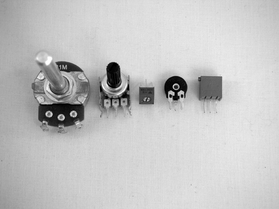
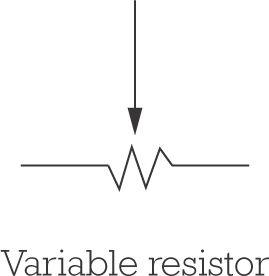
Figure A-2. Variable resistors: two potentiometers on the left, three trim potentiometers on the right, and the variable resistor symbol
The larger variable resistors, which are usually accessible from the outside of the finished project’s enclosure, are meant to be adjusted often and are called potentiometers, or pots. Very small variable resistors, which are meant to be adjusted only during the initial building stage (sometimes referred to as “set-and-forget”), are usually called trim pots, or trimmers. Any variable resistor can have either an audio (also called logarithmic) taper, or a linear taper. (For more details on this, see Audio Tapers vs. Linear Tapers in Building It.)
The pot’s value is usually printed on its face, with an A prefix for audio tapers, and either a B or no prefix for linear tapers; unless specified otherwise, you should always use linear tapers. In this book, a pot’s lugs are numbered from left to right when the pot is viewed from the front with the lugs on top, like a crown. (This means they are numbered from right to left when viewed from the back, which is the view you’ll normally have when you’re soldering; see Figure A-3.)

The shafts on pots are often much longer than you want for your final project. A good way to deal with this is to measure the depth of the knob cover you want to use (usually around 1/4″), mark this on the pot’s shaft, clamp the shaft in a vice, and cut it down with a hacksaw. If you’re worried about getting grit in the pot (not usually a problem, since most modern pots are fully enclosed), you can wrap the body of the pot in masking tape before sawing.
Pots often have small anchors protruding from their bodies; you can either drill an extra hole in your enclosure to accommodate the anchor or snap it off with a pair of pliers (Figure A-4).

Note
Resistors—fixed, variable, and otherwise—are basically indestructible; you don’t need to treat them with TLC as you start soldering.
Capacitors (Figure A-5) are composed of two wires separated by a thin insulating layer (called a dielectric). When voltage is applied to a capacitor, it stores energy. (It’s a bit like a water tower: pump the water in, and it stays there until you open the valve, at which time it forcefully pours back out.) Capacitance (a component’s ability to hold this charge) is measured in farads (abbreviated F). Because a farad is a huge amount of capacitance, most components are labeled in terms of picofarads (pF), which are larger than nanofarads (nF), which are larger than microfarads (μF). The smallest fixed capacitors—those commonly used in intro-level projects like these—are often marked in a frustratingly opaque code (which is why I’ve included Table A-2 of common values). For clarity’s sake, this book always deals in terms of microfarads.


Figure A-5. Here are some capacitors and their symbols. The two on the left are electrolytic—that is, polarized. The middle one is a Mylar-film capacitor, and the two on the right are ceramic discs.
Table A-2. Commonly used ceramic/Mylar capacitor markings and their values
Marking | Value |
|---|---|
102 | 0.001 μF |
202 | 0.002 μF |
472 | 0.0047 μF |
103 | 0.01 μF |
104 | 0.1 μF |
105 | 1 μF |
205 | 2 μF |
For the most part, small capacitors are little beige ceramic disks, or occasionally Chiclet-shaped plastic lozenges (these latter are called Mylar capacitors because they use a thin Mylar film as their dielectric). The larger capacitors are barrel-shaped electrolytic capacitors. The only difference we care about is that although ceramic discs and Mylar-film capacitors are nonpolarized (that is, it doesn’t matter which way which leg goes), electrolytic capacitors are polarized and must be oriented properly. The negative leg of an electrolytic capacitor is always marked with a thick stripe. Also, happily, electrolytic capacitors are large enough to be labeled with their value, rather than relying on the terrible code. In general, any cap under 1 μF is ceramic/Mylar, and anything over 2 μF is electrolytic.
Like resistors, capacitors are hardy components. Although it is theoretically possible to heat an electrolytic capacitor to such a degree (or apply so much current) that it pops, I’ve never known anyone who did so accidentally.
Thus far, we’ve discussed only passive components (those that obstruct the flow of electricity, decreasing or slowing a signal). Diodes and transistors are active components—they can be used to construct circuits that produce a power gain and increase the level of a signal. They can do this because they are semiconductors. While conductors (such as a piece of wire or a resistor) allow current to pass through them, and insulators (such as the plastic coating on a 24-gauge wire) stop all flow of current, semiconductors pass current in special ways.
Diodes and LEDs (light-emitting diodes), shown in Figure A-6, allow voltage of only a certain level or greater to pass (that is, the voltage must exceed the diode’s forward voltage) and will let current travel in only one direction (in other words, they have polarity). Like all polarized components, they must be mounted in the proper direction to work. The stripe on a physical diode is closest to the diode’s negative leg (its cathode) and corresponds to the crossbar at the tip of the triangle on the diode symbol. On an LED, the negative leg is the shorter leg (which is on the side closest to the flat spot on the LED lens’s edge).


Transistors are the diodes’ fancy big brothers. Like diodes, they let current flow in one direction and only if it exceeds the transistor’s forward voltage. But the three-legged transistor works like a valve: A low-current signal at the base controls a higher current that flows from the collector to the emitter. (There are many kinds of transistors, but because all the projects in this book use common NPN, negative-positive-negative, transistors, that’s what is depicted in Figure A-7 and described here.)
All semiconductors are sensitive to heat and static electricity. If you’re concerned about damaging them, use a heat sink when soldering them (details in Tools in Tools).


Integrated circuits (ICs)—shown in Figure A-8—are compact packages of microscopic diodes, transistors, and resistors, prewired to perform a given task. (Anything an IC can do, a fistful of transistors, diodes, and other basic components, plus a few yards of bus wire and some circuit boards, can also accomplish.) As such, ICs are semiconductors and are thus heat- and static-sensitive, so you must handle them carefully.

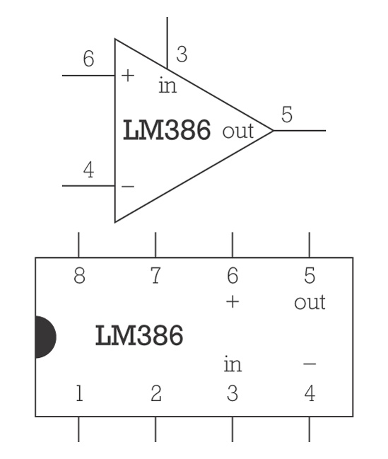
Figure A-8. On the left are two DIP-style ICs, and on the right are symbols for the lower chip, which is the LM386 op-amp used in the Dirt-Cheap Amp, Chapter 12. An IC in a circuit diagram is usually depicted as a triangle (or a series of triangles for each of its logic sections). For clarity, I’ve used little drawings of the ICs in circuit diagrams throughout this book.
When ordering ICs from a catalog or website, you should always be sure to get the DIP (dual in-line package) version (like those in Figure A-8), as opposed to the surface-mount version. DIPs look like little rectangular insects standing on 8, 14, 16, or more straight little legs and are relatively easy to work with. Surface-mount chips are flat with short legs; they are usually mounted on circuit boards by machines (you’ll find them on your computer’s motherboard); you will go insane trying to learn to solder on surface-mount chips.
In electrical work, wire is described in terms of gauge, insulation, and core.
The gauge of a wire is its thickness, with thinner wire having a higher gauge than thicker wire. For example, the 42-gauge winding wire used in guitar pickups is as thin as a human hair, while 18-gauge copper wire is nearly the thickness of a plastic cocktail straw. Conducting wire is measured using the American Wire Gauge (AWG) Standard (e.g., the guitar pickup winding wire will be labeled 42 AWG).
Any wire can be either insulated or bare (uninsulated). Thicker insulated wire usually has flexible plastic insulation, but thinner wire (20 to 30-something AWG) may be enameled—coated in a shiny polyurethane varnish—instead. Finer insulated wires (high 30s and above) are usually enameled.
Finally, a wire is either solid-core or stranded. Solid-core wire is composed of (surprise!) a single solid strand, and stranded wire comprises several strands whose total combined cross-sectional area corresponds to the wire’s AWG. Solid-core insulated wire is often called bell wire, and stranded insulated wire is called hook-up wire.
Solid-core wire is a little easier to solder into printed circuit boards (PCBs), because it fits nicely through the holes, but it can break easily with repeated bending (such as flexing when you open and close a case to check a circuit, change batteries, or make other adjustments). Stranded wire can occasionally be a headache to thread through the holes on a circuit board. As a rule, use solid-core wire for connections that won’t move much (such as point-to-point connections on a board, or when running between pieces of hardware mounted on the same surface), and use stranded wire if the wires need to flex a lot (such as for connections to a battery or to hardware running from a circuit mounted on the side of the box to hardware mounted to its top).
Bare 22- or 24-AWG solid-core wire is often called bus wire and is great for running grounds, repairing broken traces on prefabricated printed circuit boards, making jumpers, replacing lost eyeglass screws, and so on; it’s the all-purpose bailing twine of hobby electronics.
These 1/4″ jacks and plugs (commonly thought of as a “guitar jack”) were first developed for manual telephone switchboards and are often called phone jacks, which is confusing, since RCA plugs and jacks are called phono jacks, because they were the old standard on hi-fi stereo phonograph systems.
Mono 1/4″ phone jacks are also called TS connectors, because they have two lugs—one that carries the audio signal and makes a circuit with the tip of a plug when connected and another that connects the sleeve of the plug to ground (see Figure A-9).
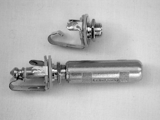
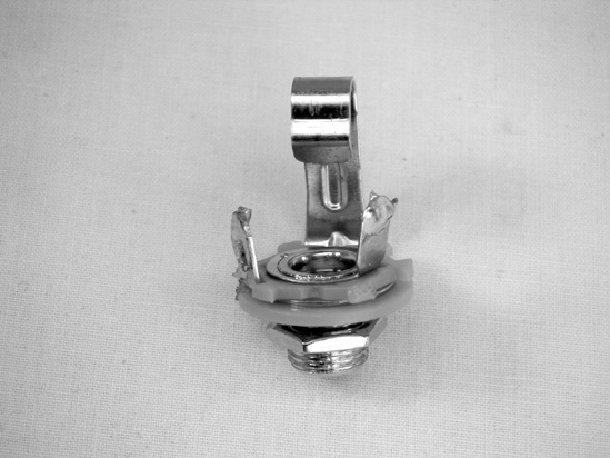
Figure A-9. On the left are two 1/4″ mono jacks—one with a plug inserted. Notice how the jack’s bent metal tongue fits into the notch at the plug’s tip. On the right, a jack with labeled lugs; as you can see, the right lug is connected to the sleeve (which connects to the circuit’s ground), and the other lug connects to the tip.
Stereo phone jacks and plugs are sometimes called TRS connectors. In this configuration, the sleeve still connects to ground, but the tip and ring each connect to an independent audio channel, allowing for stereo sound through a single cable.
A variety of battery clips and holders are shown in Figure A-10. It’s easy to forget to buy these, and then you either end up running back to RadioShack when you’d rather be testing your latest project or trying to tape leads to a battery (which makes troubleshooting frustrating, as it’s hard to be sure if the problem is the circuit or your cruddy battery connection). Make a practice of buying a bunch of these when you find them cheap, so that you have plenty on hand when you need them.
Warning
Never solder directly to a battery! Heating a battery can cause it to burst, releasing a mélange of chemicals that will burn exposed skin or, depending on the type of battery, catch fire when they contact air or moisture!
Invest in some rechargeable batteries. Newer nickel-metal hydride (NiMH) cells might seem pricey, but they are ultimately worth the cost: They are less toxic than the old nickel-cadmium rechargeable batteries, they can be recharged hundreds of times, and they actually out-perform regular alkaline batteries in high-drain applications (such as ultra-bright flashlights and digital cameras).
