Unfold each paper clip to form a free-standing hook as shown in Figure 14-3. You might need pliers to shape these the way you like and will almost certainly want the snippers to trim them down. Place the piezos brass side up on your workbench, squirt a little puddle of CA into the middle of each one, and stand a hook in the puddle. Let these dry overnight.
While your piezos are drying, you can build the rest of the circuit. As with the Cigar-Box Synthesizer (Chapter 17), this project includes a simple audio mixer (shown in Figure 14-4). To build it, solder one 10k resistor to the middle lug of each 10k potentiometer. Take a look at your enclosure, decide where you are going to mount these pots (flip ahead to Figure 14-11 for one possible layout), then cut four lengths of insulated wire long enough to reach the furthest corner of the enclosure; since these will carry audio signals, keep them under 8″ long. Solder one wire to each of the 10k resistors and a wire to lug 1 of each pot. (Remember, the lugs are numbered from left to right looking at the pot from the front with the lugs on top; for clarification, check the appendix.) Then solder the two resistor wires to the tip of the output jack (jack anatomy is discussed in the appendix, too). The third lug of each pot will ultimately be tied to the circuit’s common ground.
This circuit (Figure 14-5) is very simple, so we’ll be building it dead-bug style (as we did in Chapter 12, the Dirt Cheap Amp), instead of mounting it on a circuit board. For an illustration of how the legs are numbered on this IC, check out Chapter 12 or flip to the appendix—and remember that the legs are numbered counterclockwise from the lower left as viewed from the top, but all soldering is done from underneath!
Note
As in previous projects, it’s strongly suggested that you use an IC socket to hold the LM386 chip. These chips can be damaged by static electricity or heat, so it’s best to solder with the socket empty, even though the illustrations show the chip in place.
Bend pins 2 and 4 under the socket and solder them together, then solder a length of insulated wire to pin 3 (this is the audio input, so keep it under 8″). Now solder another insulated wire to pin 6 and the other end of that wire to one lug of the SPST (this will be the power supply). Next solder a 100 μF capacitor to pin 5 (the leg with no stripe goes to the pin); this is the audio output. The circuit, thus far, is shown in Figure 14-6.
Twist together the wire from pin 3 of the IC socket and the wire from lug 1 of either 10k pot. Solder these to the tip of the remaining jack; this is the input. Label this pot D (for dry signal).
Once the glue is dry on the piezos, carefully solder one lead of one piezo to the wire connected to lug one of the other pot. Piezo leads are pretty delicate and a pain to solder back to the piezo element, so handle these carefully. This is your recovery pickup (it will pick up the echoey signal from the spring); label this pot W (for wet signal). Set the mixer/amp assembly aside.
Look at the audio transformer; one side has two wires (if you are using the RadioShack model, they are white and red) and the other has three (blue, black, and green). Clip off the middle (black) lead, since you won’t need it. Carefully strip the blue and green leads, and solder one to each of the leads on the remaining piezo. Insulate the solder points with electrical tape. This unit, shown in Figure 14-7, is your exciter; it drives the audio signal into the spring. Solder either of the remaining wires (red or white) on the audio transformer to the free leg on the 100 μF capacitor.
Solder the red wire on the battery clip to the open lug on the SPST switch.
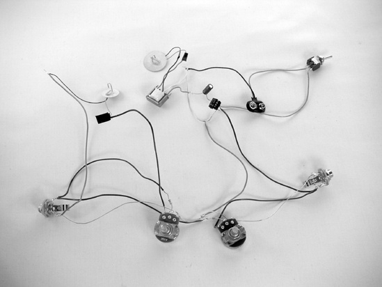
Next, you will run the ground wire. Since this will all be crammed in a box willy-nilly, you might want to use insulated wire. As in Chapter 17 (the Cigar Box Synthesizer), a shorter ground is often best here. Connect the ground lugs on both jacks, lug 3 on each pot, the remaining lead on the recovery pickup piezo, the remaining lead on the audio transformer (it will be either white or red), the black lead from the battery clip, and pins 2 and 4 on the IC socket (which you bent under the socket in Step 3). The Spring Reverb’s finished guts are shown in Figure 14-8.
Now it’s time to test the unit. Turn both pots fully counterclockwise, plug an audio source (such as an old CD player) into the input, plug an amplifier (such as the Dirt-Cheap Amp from Chapter 12) into the output, add a battery to the Spring Reverb, and flip the power switch. If the Spring Reverb is self-oscillating (i.e., howling like a heart-broken dog) or picking up local AM radio, then try connecting a 4.7–47 μF capacitor from pin 7 of the LM386 IC to the ground (the leg of the capacitor marked with the thick stripe connects to the ground). Otherwise, turn on your audio source. Slowly turn the D pot clockwise; the audio signal from your radio (or whatever) should come out of the amp basically unchanged—this is called the dry signal. Turn the D pot all the way down (counterclockwise), and then slowly turn the W pot up; now you should hear your radio tinnily playing through the exciter piezo element. Gently nudge the other piezo element (the recovery pickup piezo); the amp should scrape and thunk loudly. Turn off the audio source and amp, turn both pots fully counterclockwise, and nudge the recovery pickup piezo again. If you hear scraping coming from the exciter piezo, then there is feedback within the circuit. Try rewiring the ground to isolate the W and D pots (i.e., have the ground go back to the battery between the two). Failing all else, add a 1k resistor (brown-black-red) between the hot and ground lugs on the output, or interrupt the ground with a 1k resistor connected in series, especially on the recovery pickup’s ground connection.
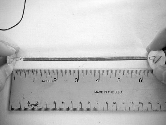
Once any intra-circuit feedback issues are resolved, switch the amp and audio source back on, turn the W pot fully clockwise, and hang the spring between the piezo elements, hammock style; you’ll hear a sproingy, tinny version of the music. Experiment with stretching the elements apart to put some tension in the spring; now you should hear the music clearly (there won’t be much bass) with lots of metallic echoes, like a radio playing inside a sealed 50-gallon steel drum at the bottom of a lifeless sea. This is the wet signal. Experiment with different amounts of tension until you find the one you like best, and measure the distance between the two piezo elements, as shown in Figure 14-9.
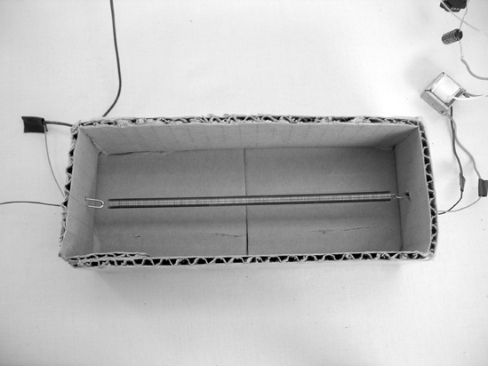
Now build your reverb tank. Turn off the amp, audio source, and Spring Reverb, and set it all aside. Take out the cardboard and build a box that is the same length as the distance you measured in Step 9 (the depth and width of the box are less important, as long as they are sufficient to keep the box from folding up under the spring’s tension; it can be just an inch or two deep and wide, as shown in Figure 14-10). Use a nail or sharp pencil to poke a hole in either end of your box. Unhook the spring from the piezo elements, feed one hook through each hole, and remount the spring. This is your reverb tank. Test it again. Because of the girth of the exciter (we’re stepping up the voltage to more than 100 volts; that piezo element would dance right off the table, given the chance) and the sensitivity of the recovery pickup, this circuit tends towards yowling feedback, with lighter springs being the most prone to problems. Adding that bypass capacitor between pin 7 and the ground (suggested in Step 9) might help with some feedback. Having a sound-absorbing reverb tank (i.e., made out of something that resonates poorly—such as sturdy corrugated cardboard—as opposed to something that resonates well, like thin, rigid plastic or a Stradivarius violin) isolated from the sides of the enclosure with double-sided foam tape is a good idea, as is keeping some distance between your amp and reverb unit (or placing the unit behind the cabinet of your amplifier). If all else fails, try packing some cotton gauze or polyfill (the stuffing used to stuff your Sock Squid in Chapter 3) around the reverb tank. If your amp doesn’t have low- and high-pass filters, you might want to build a separate passive filter box or add them to the output of the unit, as judicious EQing can tame some feedback or yowling (for simple passive filtering circuits, see Figure 17-17 in Expanding the Cigar-Box Synthesizer).
If, on the other hand, you are having no feedback problems and would like to beef up the reverb a bit, consider maxing out the amp’s gain by adding a 10 μF capacitor between pins 1 and 8 (as described in Chapter 12, the Dirt-Cheap Amp).
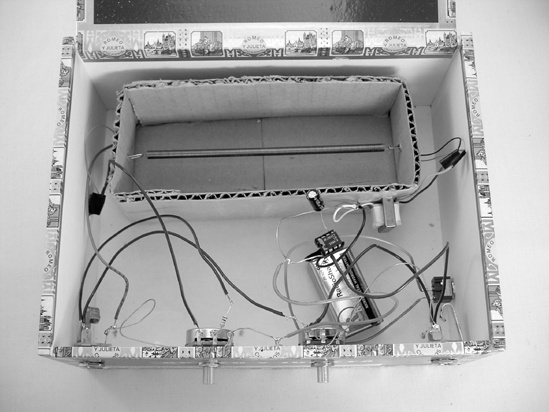
Now install this whole mess in the box of your choosing. Start by drilling a hole for the power switch (use the 1/4″ bit) and then holes for the two jacks and two pots (3/8″ or 1/2″ bits usually work fine)—you’ll note that in Figure 14-11, I’ve installed both jacks and pots on the front face of the box and the power switch on the right-hand side, but this is largely just a matter of personal preference. Before installing the jacks, switches, and reverb tank in the box, take a moment to wrap a little electrical tape around any troubling connections (points where it looks like wires might short out against each other). Then glue the reverb tank toward the back of the enclosure, bearing in mind that you’ll have fewer feedback problems if there is dead air between the reverb tank and enclosure walls. Finally, install the jacks, pots, and switch with their included hardware. The lightweight amp circuit can float around, buoyed by the wires, but you’ll want to glue the heavier transformer down (mine is on the right end of the reverb tank) and secure the battery with either double-sided foam tape or a holder clip (RadioShack part #270-326).
Plug an instrument into the input, and run the output to your amp. Use the knobs to mix the straight, unmodified signal (the dry signal) with the ersatz reverb (the wet signal). This reverb responds best to higher pitches and faster attacks; try plucking strings as though you’re playing slap bass. You can also thump the box to get zappy space-phaser sproing! sounds (early surf rock guitarists used to kick their reverb amps to get this effect).