
The trick to working with ICs is that everything is numbered counterclockwise in reference to how the chip looks when viewed from the top, but you have to work on it from the bottom. Take out your LM386 op-amp and set it on a sheet of clean paper, with the IC’s markings up and its little half-circle dimple to the left. The leg at the lower left is leg number 1. The next one to the right is 2, then 3, then 4, then the numbering wraps around: The leg at the upper right is number 5, its neighbor to the left is number 6, and so forth, as illustrated in Figure 12-3.
Flip your chip over, so that its pins stick up like little legs (dead-bug style), and the little dimple is to the right. The legs are now numbered clockwise starting with the lower right, as shown in Figure 12-4.
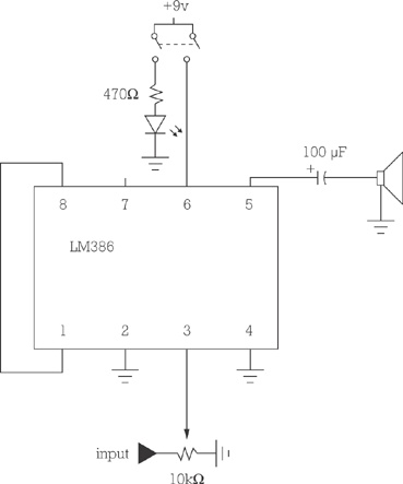
Label the legs in this new orientation, then set the chip aside, and replace it with your IC socket, also oriented dead-bug style, with legs up and aligned with your numbers. Look at the circuit diagram in Figure 12-5.
Note that legs 1 and 8 of the IC socket are shorted to each other. Since these are right across from each other (the top and bottom legs furthest to the right), you can bend them in and solder them together. If the legs of your socket are too short to reach, you can use a little snip of bus wire to connect them (as in Figure 12-6) or even a length cut from a small paperclip.
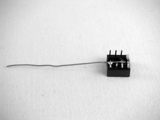
Now we’ll start our ground bus —a single wire that will tie all of the ground connections (those represented by the little triangle made of three horizontal lines) to the negative terminal of the battery (which, for the purposes of the circuits in this book, is the ground). Snip a 2″ length of bus wire. Bend down pins 2 and 4, then hold your piece of bus wire so that it runs the length of the socket, connecting pins 2 and 4 without making contact with any other pins (especially pins 1 and 8). Solder pin 2 to the bus, and then do likewise with pin 4; you should have 1″ and some change of bus wire sticking out from the left end of the IC socket, like a little tail (see Figure 12-7). Set the IC socket aside for now.
Next, solder up some of the larger components. If your speaker doesn’t already have wires attached to its lugs, then attach a length of insulated 24-gauge wire to each lug now.
To build the power switch assembly shown in Figure 12-8, short together the two end lugs of the DPST switch, then connect the red wire from your battery clip to these end terminals and a length of insulated wire to one of the two middle lugs of the switch. (If you’re using a DPDT switch, just ignore that spare pair of end lugs. For a full discussion of switches—with pictures!—flip back to Types of Switches in Building It.) Connect the resistor to the remaining middle lug of the switch, and then solder the resistor’s other leg to the positive leg of the LED (that’s the leg on the side opposite the flat spot on the LED’s red plastic lens). Set the power switch assembly aside.
Take a look at the 1/4″ mono phone jack. This jack is also called a TS connector, because it has two lugs, one that will make a circuit with the tip of a plug when connected—this lug carries the audio signal—and the other that connects the sleeve of the plug to ground. (For a fully illustrated discussion of jacks and their lugs, see the appendix.) Solder one insulated wire to each lug; keep the tip wire under 6″ (see Figure 12-9).
Solder the wire connected to the jack’s tip to the first lug on the variable resistor (this kind of adjustable resistor is usually called a potentiometer or pot—there is a labeled diagram of pots and their lugs in the appendix). The first lug is furthest to the left when you look at the pot from the front with the lugs on top, like a crown. Solder lengths of insulated wire to each of the other two lugs on your pot; the wire attached to the middle lug should be under 6″.
Turn back to the IC socket and check the schematic again. Install the 100 μF electrolytic capacitor, keeping in mind that it is polarized: The leg that lines up with the stripe running down the side of the capacitor is negative and must ultimately connect to the ground. Solder the positive leg to pin 5 and the negative leg to one of the speaker wires (either is fine, although it’s traditional to connect the capacitor to the red lead, as I have in Figure 12-10). Solder the other speaker wire to the ground bus. See how the negative leg of the capacitor is on the negative side of the circuit?
Install the input. The wire attached to the central lug of the pot goes to pin 3. The remaining wire on the pot goes to the ground bus.
Add power. Solder the dangling wire on the switch to pin 6, and then complete the circuit by soldering the final ground connection, connecting the black battery wire and the negative leg of the LED to the ground bus.
Finally, install the chip. Flip the socket over so that pins 1 and 8 are to the left. Orient your chip so that its dimple is also to the left, carefully line up all 8 legs with their holes in the socket, and gently seat it with your thumb. The complete circuit is shown in Figure 12-11.
Install the whole mess in your enclosure. In general, thinner wood (and even rigid plastic) resonates well. Both the jack and switch will fit nicely into 3/8″ or 1/2″ holes. Many speakers have mounting brackets around their edges, but Gorilla Glue will also hold a speaker snugly in place—make sure to drill some holes for the sound to pass through, or cut a hole and cover it with a screen to protect the speaker and help hold it in place (in Figure 12-1, I’ve used an old fan cover from a computer power supply).


Building the amp circuit without a circuit board (i.e., dead-bug style) results in something so light that it doesn’t really need to be secured to the enclosure; the wires going to the hardware hold it up, like the suspension on a trampoline. If you want to secure it to the enclosure, you can do so with a dab of glue or strip of double-sided tape, although that will make it harder to repair. If you’re concerned about the 9-volt battery rattling around and busting up the joint, you can likewise secure it with double-sided tape or with a handy 9-volt battery holder clip, as is shown in Figure 12-12 (RadioShack part #270-326).
