Start by examining the schematic in Figure 7-3. If the heart of the Ticklebox is the step-up transformer, then the brain is the relay, represented by the dashed box containing squares and little pennants. This is an electromagnetically controlled switch: When you power up the coil, it creates an electromagnetic field that pulls the switch closed, thus completing a circuit and turning your gadget on. When the coil loses power, the magnetic field dissipates, the switch opens, and the gadget turns off. Like other switches, relays come in SPST, DPDT, and other varieties (for a full discussion of different kinds of switches, see Types of Switches in Building It).
Figure 7-3. The Ticklebox’s full circuit diagram at the top (it is a very simple Taser), and the same circuit broken into its three component circuits
Even though it will lead to a little re-soldering, we’re going to build the three circuits one at a time, for clarity’s sake. If the diagram is suitably clear to you, feel free to just put the circuit together as you see fit. Otherwise, use the following steps.
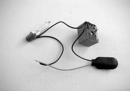
Before you start soldering, you’ll need to determine which terminals are which on your relay. Often they are labeled, either on the relay itself or its packaging (nc stands for normally closed, and no for normally open). If not, snap the 9-volt battery into its clip, and briefly connect the red and black wires to sets of terminals on the relay. When you find a pair that produce a snappy clack when the voltage is applied, those are the coil terminals—label them. You can then rig up a little circuit with an LED, a resistor, and a battery (such as the one from the Switchbox shown in Figure 2-5 in Building It), or use a multimeter (as discussed in the appendix), and poke around among the remaining three terminals to determine which are the normally closed, normally open, and common terminals of the relay’s SPDT switch. Once you’ve identified all of the relay terminals, move on to Step 2.
Solder together the control loop. The red wire of your battery clip is the positive lead, so the tilt switch should come between it and the coil. Solder the black battery lead (the ground) to the other side of the coil (the resulting circuit is shown in Figure 7-4).
Build the charging loop. Since the capacitor is polarized, be sure to connect its negative leg (the one that lines up with the stripe on the capacitor) to the black lead on the battery clip (the ground). The other leg connects to the common terminal on the relay, and then the normally open terminal connects to the positive lead on the battery clip.
Finally, build the discharge loop. Your audio output transformer should have two wires on one side and three on the other. (If you’re using the RadioShack model, one side will be red and white; the other will be green, black, and blue—if you have a multimeter, the resistance across the red and white wires should be around 8 ohms, and roughly 1000 ohms for the green and blue.) You can clip off the middle wire on the three-wire side (the black wire on the RadioShack transformer), and strip the remaining four. Solder the normally closed terminal to either the red or white wire and then the remaining wire from that side back to the ground (the black battery lead), as shown in Figure 7-5. The green and blue wires will be your contacts. You might want to solder little extensions to them, depending on how long they are, in order to make it easier to install the circuit into the box.
Hook up the battery, jiggle the tilt switch, and shock yourself a few times. If it doesn’t work, double check to be sure you have the relay wired properly.
Experiment with putting the contacts different distances apart. Yelp occasionally. Reveal military secrets.
Finish the enclosure you see in Figure 7-6. Use a thumbtack or thin nail to pop a small hole in the bottom of the box and thread one of the two contacts (the green and blue wires on the transformer) out. Use electrical tape to secure this flat against the outside of the box, being sure to leave as much of the copper core of the wire exposed as possible. Secure the other parts to the inside of the box; you can glue the relay and tilt switch down, but probably want to tape the battery in place. Cut out a square of aluminum foil a few inches larger than the box. Smooth the foil along the outside of the box bottom, making sure there is solid contact between the tip of the wire and the foil (with many boxes, it’s easiest to get good contact along the edge). Trim off the excess foil, and use strips of electrical tape to secure the foil and insulate it from the top of the box.
Pop a hole in the top of the box, thread the wire through, and tape the wire down. Cover the top of the box with foil (no need to use electrical tape to secure it; the added foil and tape on the bottom half of the box will make for a snug fit as is). It is virtually impossible to avoid shocking yourself throughout this operation. If you haven’t been getting shocked, then probably something got broken. Open the box, be sure that the foil on the box’s top and bottom don’t touch, then check all the connections to make sure none of the wires are creating a short circuit.
Close up the box and give it a jiggle. Zzzap!


