
The keystone skill for an electronics tinkerer is soldering (and, of course, its dark twin, desoldering). This section will also discuss using a multimeter, building circuits, and troubleshooting projects.
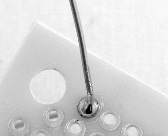
Figure A-18 shows good and bad soldered joints. In general, good soldering requires four steps, illustrated in Figure A-19 and Figure A-20: make a mechanical connection, apply heat, apply solder, then cool and trim.
Note
If your soldering iron has a brand new tip, you should tin the tip before using it. Plug in the iron, and when the tip is nice and hot, melt some fresh solder onto it to coat the tip and prevent corrosion (which will otherwise eat away the tip pretty quickly).

Before you can start, you need to preheat your iron. Then:
Make a solid mechanical connection between the components to be soldered.
Wipe the iron’s tip clean of excess solder using a damp sponge or some scrap metal, and then apply heat to the joint for a few seconds.
Touch solder to the heated joint. (Do not touch the solder directly to the hot tip of the soldering iron! Forcing hot solder onto cold joints will always make a bad solder joint.) Solder will flow over and into the joint like quicksilver. It’s very pretty. Don’t apply too much solder.
Let the joint cool, and then snip off the excess wire. Don’t move the joint until it has cooled: don’t wiggle it to see if it’s ready, and don’t blow on it to speed up the process.
If you are doing point-to-point (aka dead-bug) construction (Figure A-19), Step 1 mean twisting the legs of the components together.


If you are using a circuit board (Figure A-20), making a “solid mechanical connection” means sliding the component’s lead through the appropriate hole in the circuit board and bending the leg to one side so that it is making contact with the board’s copper pad (but not touching other components or pads, since the solder will tend to slide up the hot wire and stick to whatever other metal it finds).


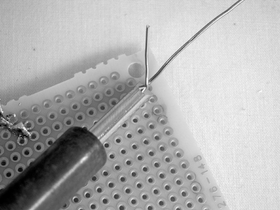

Any time you use standard wire, you should start by tinning the wires—stripping off the insulation, twisting together the strands, heating the wire, and melting solder into it, as shown in Figure A-21. This will make the wire easy to solder to other components or a PCB.


Small components whose thin legs have very little volume will heat and solder very quickly, but the lugs on hardware, especially switches and 1/4″ jacks, will take a good long while to heat up and melt the solder. If you’ve invested in a chisel-tip soldering iron, you’ll find that the sharp edge of the tip is best for working with small or heat-sensitive components, while the broad, flat face, which has more surface area to conduct heat, can make soldering hardware much faster.
Desoldering is even easier than soldering (and you’ll do it much less frequently):
Heat up your soldering iron, clean off the tip, and then apply heat to the soldered joint.
When the solder flows, use your desoldering vacuum to suck up as much as you can. (The tips of these vacuums are usually made of heat-resistant plastic.)
Repeat once or twice.
Let the joint and component cool, and then wiggle the component free with a pair of needle-nose pliers.
The soldering vacuum can also be used to remove a solder bridge, which is any place that hot solder has inadvertently flowed between two components, causing a short circuit. Just heat the offending solder and suck it up. Although you can desolder heartier components without the aid of a solder vacuum (just put on goggles, heat the solder joint, and tug at the component with your pliers, being careful not to flick hot beads of molten metal anywhere sensitive), killing a solder bridge without the aid of a desoldering tool can be very tricky.
If you are desoldering a heat-sensitive component (such as a transistor), play it safe and use a heat sink (as shown in Figure 16-4 in Building It).
For the most part, you’ll use a multimeter for three tasks: testing batteries; identifying resistors, potentiometers, and speakers; and testing continuity.
Set your meter for the proper DC voltage range. On most meters, you’ll need to use the 20-volt range for 9-volt batteries, because the batteries will overwhelm the lower 2-volt range and blow your fuse. Connect the black lead to the negative terminal and the red to the positive (Figure A-22), and see if the voltage is in the neighborhood of what it ought to be. (Advanced skill: If a circuit is misbehaving, connect the black lead to the circuit’s ground, and then start poking around with the red lead and see if the voltage levels throughout the circuit make sense. If you find an area that’s being starved of voltage, a short circuit is likely the culprit.)

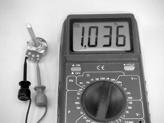
If you have an unlabeled variable resistor, you can find its maximum resistance by setting the meter to one of the ohm ranges (corresponding to your best guess of what the resistor may be), and then connecting the leads to the edge lugs, as in Figure A-23. (It doesn’t matter which goes to which; just ignore the center lug.) The multimeter will read the maximum voltage for the resistor.
You can use this same method to identify unlabeled speakers (the projects in this book all call for 8-ohm speakers, so you should be looking for speakers that give 8 ohms of resistance between their lugs) or to figure out the turns ratio of a mystery transformer you find at a garage sale or scrounge from an old piece of gear. The ratio of turns between the primary and secondary coils—which is also the ratio of the input to output voltages—is roughly equivalent to the ratio of the square roots of the resistances of each coil (you’ll want to round to two significant digits or so). To generalize this (where P stands for primary and S for secondary):
So, if you need to figure out the turns ratio on a transformer, measure the resistance on each side, take the square root of each, and then reduce the fraction so that the smaller term is a 1 (in other words, divide the big number by the small one). For the audio transformer used throughout this book:
Is it exactly right? Clearly not, but it’s a very useful approximation and spot on after you round to the nearest turn.
To test continuity (as shown in Figure A-24), choose an ohm range and connect one lead to each end of something that should conduct electricity (such as the tip or ground connectors at the ends of a guitar cable). If the meter reads anything other than 0, there’s a problem. This is also a good way to figure out which lugs are which on a complicated switch (such as the many-pole, many-throw selector knobs that can be salvaged from old medical and computer equipment).

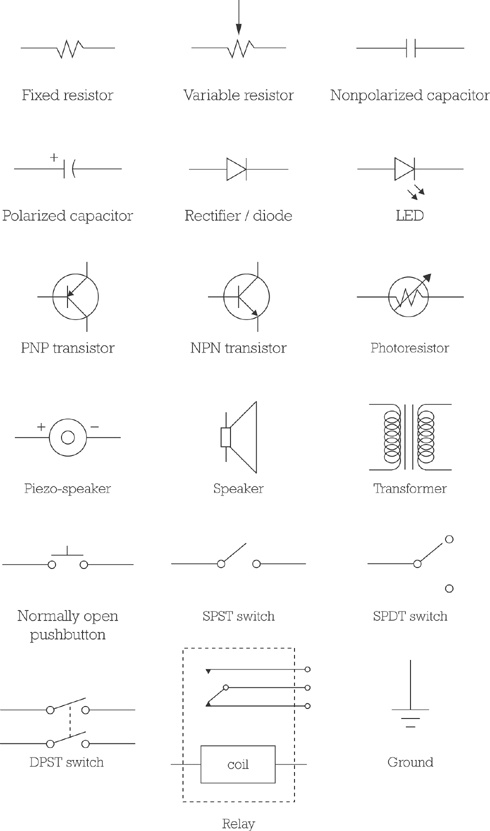
A circuit diagram is a map of the functional relationship among electrical components, drawn using symbols (such as those shown in Figure A-25). A circuit diagram doesn’t tell you the actual physical layout of the circuit. In most simple projects, if the components are connected correctly, it doesn’t really matter what is where. In some designs—especially for audio circuits—the physical layout of some parts of the circuit are sensitive; if that’s the case, it will be noted in the build notes, or the designer will provide a separate layout diagram showing exactly which physical component should be placed where on the circuit board. Most circuit diagrams flow either from top to bottom or left to right, with positive voltage or signal sources at the top or left and ground connections and signal outputs at the bottom or right.
It’s a good idea to mock up a new circuit on a solderless breadboard (see Figure A-26—you won’t find this in the kitchen) before getting out your soldering iron. Breadboards are cheap and come in many sizes. Most include a selection of pre-cut jumpers to connect everything together as you prototype your project. A nice feature of the breadboard is the central divider, which is spaced just right to hold an IC, giving easy access to each pin. This makes it a lot easier for you to hook things up correctly when you start tinkering with ICs.
To build a circuit, begin by gathering all the components you need for the project and sort them out. You don’t want to grab the wrong resistor or IC inadvertently in the heat of the moment. A cardboard egg carton is great for sorting components for a small project; avoid Styrofoam cartons if you are using ICs in your project—Styrofoam can hold a static charge on a dry day, and ICs are sensitive to static electricity. After you’ve sorted your components (and labeled them, if you want to be a suspenders-and-a-belt kind of tinkerer), build up the circuit. It’s usually easiest to start by placing the ICs or transistors and then building out from there.

Figure A-26. A breadboard with a sample circuit. Specifically, this is the Dirt-Cheap Amp from Chapter 12, with the optional gain-maximizing capacitor running from pin 1 to 8. The white wire running from pin 3 out of frame at the bottom carries the input signal. Notice that the bottom and top rails of the breadboard are being used as a common ground and power source, respectively.
After you have the circuit working on the breadboard (and you understand why it works), you can build it, either dead-bug style—soldering the components directly to each other (this is very compact but often ugly and difficult to repair or troubleshoot)—or on a printed circuit board (PCB), a sturdy, nonconductive board with copper pads and traces etched onto one side (Figure A-27).

If a circuit worked fine on the breadboard but malfunctions when it’s built, check for the following:
properly-seated ICs
shorts and solder bridges
bad solder points (a good solder point is smooth and shiny; bad ones are rough, brittle, or chunky; see Figure A-18)
reversed polarized components (e.g., electrolytic caps, diodes, LEDs, transistors, and ICs)
missed ground connections
reversed pots
shorts to ground (especially in tight enclosures—when you close the box, something could get pressed against a bare bus ground; you can prevent this by running lengths of shrink tube over the bare bus in problem areas or by using a judicious application of nail polish, which will act as an insulator when it dries)
If an audio project is noisy or is picking up AM radio, check to ensure that the audio signal lines are either shielded or less than 8″ long. (I like to err on the side of caution and keep all wires carrying audio signals under 6″, with the exception of lines running from the amp to the speaker, since the amplifier signal is strong enough to drown out any interference that might creep in at that point.)