Software systems differ in terms of their purpose, size, complexity, provided functionality, quality needs, intended usage, expected or required execution context, involved stakeholders and their concerns, level of criticality to system users, and so on. An argument can be made that this is precisely why software is difficult to develop. However, such differences across individual systems are not unique to software engineering. They can be found in any complex system and any engineering discipline.
As an example, consider two different products of modern engineering: airplanes and television sets. Both airplanes and televisions are complex systems, but their functionalities differ a great deal. They also have very different quality requirements. While it is certainly important for a television to function reliably, in the case of airplanes reliability can be a matter of life and death. Travelers expect airplanes to be robust in the face of atypical situations such as storms, turbulence, loss of cabin air pressure or engine or electrical power, and physical damage to the aircraft. On the other hand, consumers understand when, say, an electrical power surge damages their TV set and are content to wait for the TV to be repaired or simply will buy a new one. People expect that an airplane may be in use for decades and that it will need to be refurbished and upgraded during that time. They do not have the same expectations of a television.
Airplanes and televisions are products of (very) different engineering problem domains. As a result of these differences, the respective skill sets of the engineers working in the two domains also are likely to be specialized and very different: It would be unrealistic to expect an electrical engineer working on airplanes to be able to switch to building televisions without (perhaps significant) retraining, and most people would feel uneasy if they were flying on an airplane built by engineers who usually design televisions. There are many obvious reasons for this—the main one is that the problems solved in the two domains require different principles, techniques, processes, and tools that are honed separately over years or decades. Simply put, the two problem domains demand different solutions, and those developed for one domain are highly unlikely to fit the other.
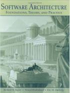
Each application domain may further have several subdomains. For example, in the context of avionics, different subdomains may encompass rotary-wing aircraft (helicopters) versus fixed-wing aircraft (airplanes), military versus commercial aircraft, jet engine versus propeller engine aircraft, and so on. Within a single domain or one of its subdomains, organizations often focus on constructing populations of related systems. For example, Boeing engineers work on a wide variety of commercial and military aircraft that are likely to share some engineering characteristics. More easily recognized are the more closely related families of systems, or product lines, that exist within those populations. In the case of Boeing, an example would be the 7×7 family of passenger airliners. A family may be defined even more narrowly, for example, to encompass different models of the Boeing 747 jumbo jet.
It is reasonable to expect that even within the domain of avionics, the skills of an engineer working on rotary-wing aircraft may differ from those of colleagues working on fixed-wing aircraft. Likewise, an engineer building a military jet may have different experience and expertise than an engineer building a commercial airliner. Even more specifically, engineers working within Boeing's commercial airliner division likely approach certain aspects of their craft differently from their counterparts at Airbus. Additionally, there is a great deal of overlap regarding how different members of the Boeing 7×7 family of passenger jets are constructed; while many of the underlying principles are the same, the comparable Airbus airliners are likely to have been designed and built differently.
An analogous narrowing of the problem scope and specialization of the engineers' skills can be observed in other domains. For example, in the consumer electronics domain, a Philips engineer is likely to have somewhat different skill sets from, say, a Sony engineer. As another example, within the automotive domain, some General Motors engineers may focus on the broad population of GM vehicles while others may focus more narrowly on, say, the family of Cadillacs. Figure 15-1 illustrates this progressive narrowing of the problem scope and the resulting growth in commonality among systems.
As with any profession, software engineers have basic skills, techniques, guidelines, and tools that are applicable independent of the target domain. Separation of concerns, modularity, object-orientation, design patterns, UML, Java, CORBA, and so on, comprise a common "toolbox" at the disposal of software engineers. It would not be unfair to think of these as equivalent to, say, Maxwell's laws, soldering irons, capacitors, resistors, and so on, that are at the disposal of an electrical engineer.
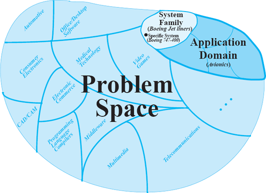
Figure 15-1. Engineers construct systems within many problem domains, which are broken down into subdomains, which in turn are broken down into families.
However, these basic tools and principles are only a rudimentary foundation for the construction of complex systems. They neither attempt to leverage the useful properties of a given problem domain nor help to identify and exploit the similarities that are likely to exist across systems in a given family. It would be too difficult, risky, and costly to attempt to build every software system using only these primitive tools. In the early days of computing, software engineers were forced to do exactly that. They had little or no knowledge about building software, especially within particular domains, so they had to develop software systems from "first principles."
The situation today is very different. A large amount of software engineering knowledge has been acquired through extensive experience (and costly failures) in many domains. Within these domains, many product populations and product lines have been developed and evolved. By leveraging knowledge from these experiences, engineers can build subsequent systems within the same domain or family more quickly, cheaply, and reliably. To use our earlier analogy, while the ability to build a television may not translate to the ability to build an airplane, the ability to build one airplane imparts a large amount of information about how to build another.
Domain-specific software engineering (DSSE) is the name given to an approach to software engineering that is characterized by extensively leveraging existing domain knowledge. DSSE is a powerful strategy for several reasons:
The requirements for a system can be divided into those common across the application domain and those unique to the system.
The common requirements can be tied to the existing canonical solutions, allowing developers to focus on the remaining subset.
The system implementation, testing, and maintenance are simplified because of the already-existing reusable software "assets" (such as engineering knowledge, design models, implemented subsystems, test suites, deployment scripts, and so on).
Development activities are simplified through software tools and environments that are specialized for the domain.
Any concerns are more easily communicated among the system's stakeholders because of the shared understanding, experience, and even terminology, which may have been developed incrementally and may be specific to the application domain.
As we will elaborate in this chapter, DSSE combines insights from three principal areas:
The domain, which scopes the discourse, the problem space, and the solution space.
Business goals, which motivate the work and help engineers decide why they are doing what they are doing.
Technology, which is used to facilitate development and reuse of domain- and business-specific assets.
The respective roles of and relationships among these areas are depicted in Figure 15-2, which provides a conceptual basis for the remainder of this chapter. It allows us to define, relate, and explain appropriately two key facets of DSSE: domain-specific software architectures (DSSA) and product families, also referred to as product lines (PL). Even though they are closely related, these two areas of software engineering have received mostly separate treatments in the literature.
This chapter introduces and discusses the DSSE concepts foreshadowed above, with a particular focus on the role of software architecture in DSSE. By the end of the chapter, the reader will better understand how DSSE is different from ordinary architecture-based software engineering, its benefits, the relationship between DSSAs and product lines, and how to apply the resulting concepts to capture explicitly and effectively architectural solutions that span multiple systems across a domain or, more narrowly, across a system family.
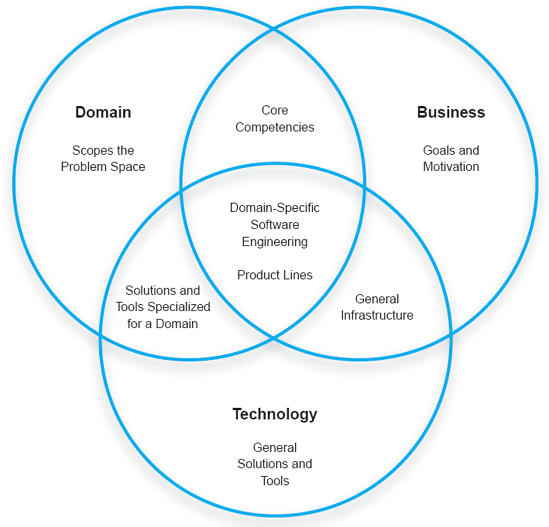
Figure 15-2. Domain-specific software engineering requires organizations and engineers to leverage different aspects of three inter-related areas: domain, business, and technology.
Outline of Chapter 15
15 Domain-Specific Software Engineering
15.1 Domain-Specific Software Engineering in a Nutshell
15.1.1 Similar Problems, Similar Solutions
15.1.2 Viewing DSSE Through the Prism of Domain, Business, and Technology
15.2 Domain-Specific Software Architecture
15.2.1 Domain Knowledge
15.2.2 Canonical Requirements
15.2.3 Canonical Solution Strategies—Reference Architectures
15.2.4 Product Lines and Architecture
15.2.5 Product-Line Concepts
15.2.6 Specifying the Architecture of a Product Line
15.2.7 Capturing Variations over Time
15.2.8 Using Product Lines as Tools for What-If Analysis
15.2.9 Implementing Product Lines
15.2.10 Unifying Product Architectures with Different Intellectual Heritage
15.2.11 Organizational Issues in Creating and Managing Product Lines
15.3 DSSAs, Product Lines, and Architectural Styles
15.4 DSSE Examples
15.4.1 Koala and Consumer Electronics
15.4.2 Software Defined Radios
15.5 End Matter
15.6 Review Questions
15.7 Exercises
15.8 Further Reading
Before we go on to the specifics of DSSAs and product lines, let us provide a brief context for them.
For the purpose of illustrating our discussion, we show a highly simplified view of traditional software development in Figure 15-3: A team of software engineers is typically given a description of a problem that they are to solve. That description may be detailed or may be cursory; it may be written down precisely or stated verbally (and ambiguously) by a human customer or prospective user; the description may be relatively complete or it may emerge incrementally during the development process. In any case, the principal task of the software engineers is to find a way of taking the problem description, which exists in the problem space, and mapping it to a software system, which exists in the solution space. Doing so in general is difficult because the two spaces usually are characterized by different concepts, with different terminologies and different properties. Doing so is also difficult because, in general, there are often many possibilities for addressing a given software requirement, ranging from the programming language in which the requirement will be implemented, to the code-level constructs used to realize the requirement, to the hardware platform on which it will execute, to the different ways of modularizing the system (including choosing not to modularize it at all), and so on. This is, in part, why historically it has been such a challenge for developers to ensure desired properties in software systems: too many choices without a clear indication of which choice works best, and why.
Figure 15-3. A deliberately simplified view of traditional software development: Any given software development problem can be solved in a large number of different ways.
Software architecture-based development addresses this problem in part by elevating the discourse to a higher plane with fewer choices: What are the principal components needed for the given system? What are their interactions? What are their compositions into system configurations that effectively solve the problem at hand? Figure 15-4 depicts this approach to system development. Again, the picture is deliberately oversimplified to illustrate the point: A problem will often have a more constrained number of software architectural solutions that are known to be effective for solving it. In turn, each of those architectures will have a comparatively smaller number of possible implementations (for reasons that have already been discussed in the preceding chapters).

Figure 15-4. A deliberately simplified view of architecture-based software development: Any given software development problem can be solved by a finite number of software architectures.
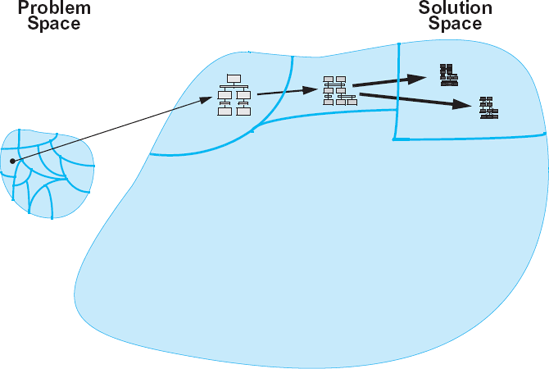
Figure 15-5. A deliberately simplified view of DSSE: Some software development problems belong to specific classes of problems for which known (partial) architectural and implementation solutions exist. Those partial architectures are then tailored to the specific problem at hand and implemented using well-understood techniques.
Still, the task of selecting the appropriate software architecture and implementing it is anything but trivial. In many ways, this problem only interposes one additional level of indirection into the problem that software engineers faced in the past. This is where DSSE takes a markedly different approach, as depicted in Figure 15-5: Instead of primarily attacking the solution space, DSSE is guided by the observation that certain problems belong to specific, well-defined problem classes, or domains (recall Figure 15-1). That is, these problems share a number of characteristics that allow engineers to attack them in similar ways. Within each domain, effective (partial) architectural solutions can be identified and documented. These solutions are known as reference architectures. Instead of developing new architectures for each new problem in the domain, solutions can be derived by tailoring the reference architecture. Furthermore, the commonalities across the different problems in the same domain allow engineers to develop solid intuitions about a system before it is built, evaluate their solutions in a principled and often rigorous manner, and leverage a large number of powerful tools for generating and evaluating system implementations. All of the resulting activities, techniques, and tools are aided by their relatively narrow, well-defined focus and scope.
As argued in the chapter's introduction and depicted in Figure 15-2, three principal concerns of DSSE are domain, business, and technology (Medvidović, Dashofy, and Taylor 2007). The prominence of each of the three concerns, and their exact mix, will differ across organizations and projects. Those differences have clear implications on the organizations and projects concerned, as well as on the stakeholders, the processes, and ultimately the products. We discuss each area in the diagram from Figure 15-2 in more detail below.
Domain: The domain, independent of business and technology concerns, establishes a problem space. It has defined characteristics, a vocabulary, a motivation (why this domain exists), and so on. This area will be further expanded below.
Business: Business, independent of any domain or technology concerns, is largely concerned with human goals: improving people's quality of life through the creation of new products, attaining money, power, notoriety, and so on. These goals motivate people to solve problems. Note that this is not meant to imply that domain-specific software must be sold or otherwise developed for the purpose of attaining monetary profits. However, the goal of using DSSE is to optimize certain aspects of software engineering: reducing cost or time to develop, improving the quality of products in the market (even open-source products), and so on.
Technology: Technology, independent of a domain or business goals, comprises tools, applications, reusable components, infrastructure, and methods that can be applied generally. In this sense, technology could be characterized as "solutions without problems."
Domain + Business: When business goals are applied to a particular domain, expertise and core competencies emerge. Business organizations specialize their skills to optimize them for particular domains: building televisions or airplanes, for example.
Business + Technology: Regardless of the domain(s) in which it operates, a business organization will acquire and develop technologies that are relevant to its overall goals but that can be applied to many domains. For example, any software development organization undoubtedly will have an infrastructure containing compilers, operating systems, networks, office applications, and so on that does not apply specifically to any domain.
Domain + Technology: This intersection contains tools, methods, and even architectures that are specifically applicable to a particular domain, but are independent of any particular business goal. For example, a programming language and compiler that are specifically developed for building aircraft software would fall into this category.
Domain + Business + Technology: This is the core of domain-specific software engineering: business goals motivating the identification and creation of a solution in the problem space of a domain, facilitated by the use of technology.
We have outlined the various concepts and interactions that comprise domain-specific software engineering. Now, we will examine how software architecture can be leveraged and specialized for application in the context of DSSE. We will study two key architecturally relevant areas of DSSE: domain-specific software architectures and product lines.
A domain-specific software architecture (Tracz 1995; Coglianese, Smith, and Tracz 1992; Tracz 1994; Tracz, Coglianese, and Young 1993) comprises a codified body of knowledge about software development in a specific application domain. Barbara Hayes-Roth (Hayes-Roth et al. 1995) provides a useful operational definition of a domain-specific software architecture:
Definition. A domain-specific software architecture (DSSA) comprises:
A reference architecture, which describes a general computational framework for a significant domain of applications.
A component library, which contains reusable chunks of domain expertise.
An application configuration method for selecting and configuring components within the architecture to meet particular application requirements.
Figure 15-6 provides an generalized overview of a DSSA-centric software development process. In addition to the usual application engineering activities in which developers engage, DSSAs involve a number of domain engineering activities. These activities result in models of the application domain's relevant entities, their characteristics, and their relationships; definitions of the key terminology; canonical requirements; design- and implementation-level solutions that are reusable across systems in the domain; and tool support specialized to aid development within the domain.
This body of assets does not come for free. Instead, it is built over time, as engineers amass experience (both good and bad) of building individual systems within a domain and try to generalize that experience for use in future systems. In the remainder of this section we will discuss the characteristics of application domains and domain models, the requirements that remain stable and those that change within a domain, and the corresponding solution strategies. We will illustrate the discussion with an example DSSA derived from the different Lunar Lander architectures discussed in the preceding chapters.
As we have discussed, one of the main concerns of domain-specific software engineering is the problem domain itself. In order to exploit the properties of the domain, its key characteristics must be captured in a domain model. Simply put, a domain model (Batory, McAllester et al. 1995) is a representation of what happens in an application domain. This includes the functions being performed, the objects (also referred to as entities) performing the functions and those on which the functions are performed, and the data and information flowing among the entities and/or functions. In the parlance of the preceding section, a domain model deals with the problem space. Therefore, the above terms are used in their ordinary sense (for example, function as an operation performed on or by an entity "living" in the domain), rather than in the sense that software engineers typically assign to them (for example, function as a method that returns a value in a C++ program).

If we take avionics as an example domain, the functions of interest would be aircraft takeoff, landing, taxiing, flying, pitch, roll, yaw, fueling, refueling (possibly in-flight), maintenance, and so on. Data and information flowing among these functions would be various pilot commands, instrument signals, warnings, status check messages, fuel consumption rates, data collected for the black boxes, and so on. The entities in the domain would include the flight instruments, the aircraft's rudder and wing flaps, the fuel tanks, the fuel transferred into the tanks during fueling and from the tanks to the engine during flight, the hydraulic fluids used to control the aircraft, and so on. It is this type of terminology, entities, their relationships, and operations on them that go into constructing a domain model.
Note that nothing in the above (very brief and informal) domain description belies the fact that a significant portion of a given avionics system's functions, data, and entities eventually will be reified in software. Remember, the domain model characterizes the problem space. The fundamental objective of a domain model is two-fold:
A domain model standardizes the given problem domain's terminology and its semantics. Together, the terminology and semantics are referred to as the domain's ontology.
A domain model provides the basis for standardized descriptions of problems to be solved in the domain.
For example, yaw is a term used in avionics to refer to an aircraft's rotation about an axis that is perpendicular to the aircraft's horizontal plane (that is, its wings) and goes through the aircraft's center of gravity. We would, of course, also have to define what a center of gravity is, and then any other terms needed to clarify its definition, and so on, until all the terms related to yaw are explained using the appropriate domain-specific terminology. Yaw is produced by moving the aircraft's rudder.
Note that while yaw is a widely known term because of the popularity and ubiquity of flight in today's world, nothing really prevents us from using a different term to describe this same concept in another problem domain. For example, we might call the analogous movement of a flat-panel television screen left-right rotation. Similarly, we can use this same term to describe a different concept in another problem domain (although in this case we would risk confusing matters given the broad familiarity with this particular term and its above-defined meaning).
A domain model is a product of context analysis and domain analysis. Context analysis is the activity whereby the boundaries of a domain are defined, and the relationships of the entities inside the domain to those outside it are identified and captured. This is an important activity that sometimes remains overlooked, since DSSE focuses primarily on things within a domain, rather than the bounds of the domain or the relationship between things inside and outside the domain.
Domain analysis can be defined as the activity of identifying, capturing, and organizing the domain assets, that is, the objects, operations, and data recurring across a class of similar systems within an application domain. Domain analysis results in a description of the domain assets using a standardized vocabulary. Its goal is to set the foundation of making the assets usable and reusable when solving new problems within the domain. For example, yaw is a usable asset if it is described in a manner that allows an avionics (software) engineer to find it easily and understand its meaning unambiguously whenever needed. Yaw is re usable if it describes an operation of all, or at least most, aircraft within the domain (for example, large passenger airplanes). Note that this level of reuse, while clearly important to multiple projects conducted by an engineering organization, including its software engineering divisions, has little if anything to do with code.
A domain model will usually comprise several pieces of information that together present a useful picture of the domain assets and their interrelationships. These models can be grouped into four categories:
Domain dictionary
Information model
Feature model
Operational model

The different models and a broad cross-section of their associated diagram types are shown in Figure 15-7. We now discuss each of them in more detail.
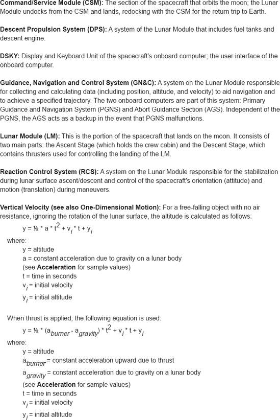
A domain dictionary represents the identification and definitions of terms used in the domain model. These terms may be widely used and understood outside the domain, in which case the goal of including them in the domain dictionary may be to define them carefully and avoid any inconsistencies and ambiguities in their usage. On the other hand, the terms may be specialized, or even invented for the sole purpose of fostering human stakeholders' communication and understanding within the domain. The domain dictionary should be updated over time with new terminology and with new or clearer understandings of existing concepts. A domain dictionary also becomes an indispensable tool for training new engineers working within the application domain. Figure 15-8 shows a partial domain dictionary from a hypothetical Lunar Lander DSSA.
An information model is actually a collection of multiple models that may be used in different organizations and different DSSAs. The information model is a result of context analysis and information analysis. Context analysis results in defining the boundaries of the domain and preserves information that may be otherwise implicit and scattered across many different systems and their artifacts. Information analysis then takes the result of context analysis (that is, the contours of the domain) and represents the intradomain knowledge explicitly in terms of domain entities and their relationships.
The information model ensures that the DSSA employs appropriate data abstractions and decompositions. Different elements of the information model are used by at least three types of stakeholders.
Requirements engineers use the information model as an aid in precisely specifying the reference requirements, that is, the requirements common across the applications in the DSSA (see the "Canonical Requirements" section below for a detailed discussion of reference requirements). They also use the information model to relate appropriately the application-specific requirements to the reference requirements.
Software architects use the information model to identify and appropriately relate the modules in the software system in the manner that reflects the characteristics of the domain, the interfaces exported by those modules, the data exchanged among them, and the mechanisms by which and constraints under which data is exchanged. This activity results in a reference architecture (see the "Canonical Solutions" section below for a detailed discussion of reference architectures). Software architects also use this information to relate application-specific architectures and designs to the reference architecture.
Software system maintainers use the information model to understand the manner in which any given application in the DSSA addresses problems. This enables them to relate properly the system maintenance and evolution requirements to the reference requirements and application-specific requirements, and to relate their proposed realization in the system to the reference architecture and application-specific architecture.
An information model usually consists of one or more of the below types of diagrams.
Context Information Diagram. This diagram captures the high-level data flow between the major entities in the system, their relationship to the entities outside the system (as well as outside the domain), as well as any data that is assumed to come from external sources. For example, in the Lunar Lander DSSA, the information exchanged among the spacecraft's sensors, actuators, and computers is part of the context information diagram. At the same time, the topology of the moon's (or planet's) surface on which the spacecraft is landing is considered to be outside the domain. An example context information diagram from the Lunar Lander DSSA is shown in Figure 15-9.
Entity/Relationship (ER) Diagram. This diagram captures aggregation ("a-part-of") and generalization ("is-a") relationships among the entities within the domain. For example, in the Lunar Lander DSSA, fuel level is "a-part-of" the spacecraft entity, while a given thruster "is-a" Lunar Lander actuator. An example ER diagram from the Lunar Lander DSSA is shown in Figure 15-10.
Object Diagram. This diagram identifies the objects in the application domain rather than in the software. In other words, the object diagram describes entities in the problem space; the solution-space components used to realize the problem-space entities will be captured in the reference architecture, discussed below. The object diagram captures the attributes and properties of each object, as well as their interdependencies and interactions with other objects in the domain. An example object diagram from the Lunar Lander DSSA is shown in Figure 15-11.

The feature model is, in fact, a collection of several models. A feature model results from feature analysis. The goal of feature analysis is to capture and organize a customer's or end-user's understandings and expectations of the overall (shared) capabilities of applications in a given domain. The feature model is considered to be the chief means of communication between the customers and the developers of new applications. The feature model explicitly delineates the commonalities and differences among systems in the domain. Examples of features include function descriptions, descriptions of the mission and usage patterns, performance requirements, accuracy, time synchronization, and so on (Kang et al. 1990). Such features are meaningful to the users and can assist the engineers in the derivation of DSSA that will provide the desired capabilities.

Features may be defined as mandatory, optional, or variant. Mandatory features are expected to recur across all systems in the domain. In the case of the Lunar Lander system, Compute Altitude is a mandatory feature: Any implementation of the Lunar Lander must be able to continuously compute the spacecraft's altitude. Optional features are those that are identified as useful for a subset of the systems within the given DSSA. For example, Get Burn Rate is an optional feature: Some versions of the Lunar Lander are able to ask the system user for the preferred fuel consumption rate. Finally, variant features exist in most (or all) systems within a DSSA, but differ depending on the values of one or more parameters. For example, Compute Velocity is a variant feature within the Lunar Lander DSSA, whose exact realization may depend upon the size and mass of the spacecraft as well as the size, mass, and atmosphere of the celestial body onto which the spacecraft is landing.

The feature model also encompasses several types of diagrams, which are discussed below. As with the information model, the architects developing the feature model for a particular DSSA would decide which of these diagrams best suit their needs. They might also choose other types of similar diagrams. For example, Software Engineering Institute's Feature Oriented Domain Analysis (FODA) approach advocates the use of semantic networks (Kang et al. 1990) in feature modeling.
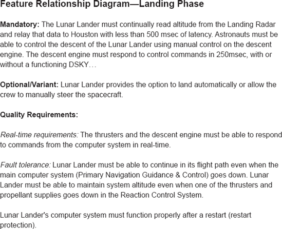
Feature Relationship Diagram. [20] This diagram describes the overall mission or usage patterns of an application. It captures the major features and their decomposition into subfeatures. This model can also include any quality requirements associated with individual features such as dependability, security, performance, accuracy, real-time requirements, synchronization, and so on (recall Chapters 12 and 13). An example feature relationship diagram from the Lunar Lander DSSA is shown in Figure 15-12.
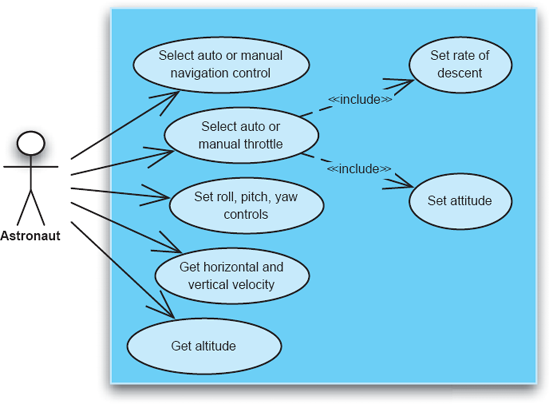
Use-Case Diagram. This diagram captures the usage scenarios in the system. Use cases have become prevalent with the introduction of the Unified Modeling Language (see Chapters 6 and 16). Use-case diagrams are elicited from domain experts, system customers, and system users, and encompass the manner in which a feature is expected to be used, as well as control- and data-flow among multiple features. An example use-case diagram from the Lunar Lander DSSA is shown in Figure 15-13.
Representation Model. This diagram describes how information is made available to a human user. In other words, the representation model details what the appropriate user interfaces are for the systems within the DSSA. This model also captures the information produced for another application: What kinds of input and output capabilities are available, and what is the expected, common format for the exchanged information? An example partial representation model from the Lunar Lander DSSA is shown in Figure 15-14.
The operational model is the foundation upon which the software designer begins the process of understanding (1) how to provide the features for a particular system in a domain, and (2) how to make use of the entities identified in the resulting domain model. The operational model identifies the key operations (that is, functions) that occur within a domain, the data exchanged among those operations, as well as the commonly occurring sequences of those operations. In other words, the operational model represents how applications within a domain work.

Figure 15-14. Example representation model from the Lunar Lander DSSA. Original DSKY diagram from Apollo Operations Handbook, Lunar Module LM5 and Subsequent, Volume 1: Subsystems Data (LMA790-3-LM5).
The operational model is a result of operational analysis, which identifies the commonalities as well as differences in control-flow and data-flow among the entities in a domain. The domain-wide entities identified in the information and feature models, discussed above, form the basis for the operational model: The information model captures the data exchanged by the operations, while the feature model captures the operations themselves. The control- and data-flow of each individual application within the DSSA can be derived from the operational model.
Three representative types of diagrams used within the operational model are discussed below.
Data-Flow Diagram. This diagram focuses explicitly on the data exchanged within the system, with no notion of control. An example data-flow diagram from the Lunar Lander DSSA is shown in Figure 15-15.

Control-Flow Diagrams. This diagram focuses on the exchange of control within the system, without regard for data. An example control-flow diagram from the Lunar Lander DSSA is shown in Figure 15-16.
State-Transition Diagram. This diagram models and relates the different states that the entities in the domain will enter, events that will result in transitions between states, as well as actions that may result from those events. An example state-transition diagram from the Lunar Lander DSSA is shown in Figure 15-17.
A critical element of a DSSA is the canonical or reference requirements. These are requirements that apply across the entire domain captured by a DSSA. Such reference requirements will be incomplete because they must be general enough to capture the variations that occur across individual systems and because individual systems also will introduce their own requirements. However, reference requirements directly facilitate the mapping of the requirements for each system within a given domain to the canonical domain-specific solution (discussed in the next section).
Similar to the requirements for any software system, the starting point for reference requirements is the customer's statement of needs. In a DSSA, this statement is general enough to apply to any system in the domain. A DSSA is an exercise in generalization from specific experience, so the statement may emerge over time from similar statements that were specific to individual systems constructed previously within the domain. The customer needs statement identifies the functional requirements for the DSSA at a high level of abstraction. It is usually informal, ambiguous, and incomplete. It is a starting point for deriving (reference) requirements, but it is not the same as reference requirements. As an example, Figure 15-18 shows a partial customer needs statement for the Lunar Lander DSSA.


Reference requirements are then derived from the customer needs statement as well as the requirements of the individual legacy systems within the domain. The reference requirements contain the defining characteristics of the problem space. These are the functional requirements. Reference requirements also contain limiting characteristics (that is, constraints) in the solution space. These are the non-functional requirements (such as security, performance, reliability), design requirements (such as architectural style, user interface style), and implementation requirements (such as hardware platform, programming language).


Similar to the feature model discussed above, reference requirements must distinguish among three types of requirements:
Mandatory requirements are applicable to all systems in the domain.
Optional requirements are known to be applicable to a certain set of systems within the domain.
Variable requirements are application-specific, and may be unknown at the time the DSSA, and more specifically reference requirements, are formulated.
In general, each requirement—whether functional, non-functional, design, or implementation—can be of any one of the three types (mandatory, optional, or variable). We provide examples of mandatory, optional, and variable requirements for the Lunar Lander in Figure 15-19.
When business goals and technology are applied to a problem within a domain, solutions emerge. A single product architecture represents a single solution. However, as we have covered extensively, when attacking problems in the same domain with similar business goals in mind and leveraging similar technology, similarities will emerge in solution architectures. These similarities can be captured in a reference architecture. Here, we repeat the definition found in Chapter 3.
Definition. Reference architecture is the set of principal design decisions that are simultaneously applicable to multiple related systems, typically within an application domain, with explicitly defined points of variation.
As sets of principal design decisions, reference architectures are themselves architectures. However, they are generic or variegated such that they are applicable to multiple systems simultaneously—in the context of the terms we have used in this chapter, to a population or a product line of systems. Points where the architecture can vary from family member to family member are explicitly defined as part of the reference architecture.
There are many different kinds of reference architectures; this definition is intentionally broad. They differ in how they express the commonalities and the points of variation in a population or product line. Three classes of reference architectures are:
Complete single-product architecture: An ordinary product architecture of a simple toy example or a complete system for a particular domain can be considered a reference architecture, since it might serve as an exemplar for future products in the same domain. Such reference architectures are relatively weak because they do not provide much engineering guidance as to how to use the reference architecture to create new systems, and they do not explicitly call out variation points.
Incomplete invariant architecture: A partial architecture can be specified that is constant and unchanging among all products. Parts of the architecture that vary from product to product are left unspecified, although some design guidance might be provided as to how to "fill in the blanks" in the architecture.
Invariant architecture with explicit variation: This kind of reference architecture can be used to simultaneously capture both the invariants and the variants in products in a domain. For each variation point, permitted alternatives are specified in detail.
Developing a reference architecture is a serious decision because it will be the guiding foundation for a number of future products. Determining when, how, and why to develop a reference architecture is critical to success.
When to Develop a Reference Architecture. An obvious question that arises in DSSE is, "When is the right time to develop a reference architecture?" Choosing an appropriate time is critical because a reference architecture will constrain and bind all solutions in the domain. Premature development of a reference architecture can be disastrous if the architecture is not validated or the stakeholders' understanding of the domain is too incomplete: Instead of affecting just one product, a mistake made in a too-early reference architecture will propagate to many products and vastly increase the costs of that mistake. On the other hand, developing a reference architecture too late can be equally costly: If many diverse solution architectures have already been developed in a domain, then there will be little opportunity to adapt these existing architectures to fit the reference architecture (they will become "legacy systems"), and therefore substantially limit reuse benefits.
A good tactic that mitigates some risk is to adopt an incremental approach with respect to reference architecture. The reference architecture should still be developed with the entire family of products in mind—if this is not done, it may take on the characteristics of a single product and later have to be significantly adapted to incorporate the full family. If, as is often the case, a number of products have already been developed and they are being adapted to use a reference architecture, it is usually easier to adapt one or two products at a time to use the reference architecture rather than try to unify the family all at once. Starting with the products whose existing architecture is closest to the target reference architecture is generally a good idea. This allows the reference architecture to be evaluated and refined without affecting too many products simultaneously.
Choosing the Form of a Reference Architecture. Deciding how to capture a reference architecture depends on the domain, the stakeholders, and the underlying business needs of the organization(s) involved. More precise modeling techniques (such as the use of explicit variation points) make it easier to detect and prevent phenomena such as architectural drift and erosion, but might also limit creative freedom and opportunities for innovation.
A complete single product architecture offers the least guidance to architects as to how to elaborate it into a family of products (unless the products in that family have architectures that are very close to the reference architecture). If this form is chosen for the reference architecture, explicit documentation of the underlying style and what is and is not allowed to change should be provided as well. It may also be useful to include several examples of complete product architectures in a family to illustrate this.
Incomplete invariant architectures have the advantage that they tell architects directly what must be present in a family member's architecture. However, they may lack details about how to actually complete the elaboration process. Again, important documentation about the style and how elaboration should proceed is important. Another (somewhat costlier) alternative is to combine this with complete product architectures: that is, as part of the reference architecture, provide both the incomplete invariant architecture and one or more elaborated product architectures (even if these are only samples or demonstration architectures) as these can serve as examples for future elaborations.
Invariant architectures with explicit variation points provide the most direction to architects; not only do they say exactly what must be present in every family member's architecture, but they also effectively define all the members of the family. A reference architecture in this form may have a large number of variation points, and the sum of all possible alternatives will far exceed the business needs of the developing organization. For example, imagine such a reference architecture that defines eight optional features that may be included or not included. This reference architecture defines a family of 28=256 possible architectures. Not all of these architectures will be feasible (due, perhaps, to feature conflicts) or desirable to produce (due to market conditions). These reference architectures make it easy to select family members, but limit the scope of the products that can be in the family at all.
For a complex domain, a reference architecture will be extremely detailed, with multiple coordinated views, extensive documentation capturing the invariants and variation points, and guidance on how to refine the reference architecture into a concrete application. Rationale for the various decisions embodied in the architecture would also be included. A structural view such as the one shown in Figure 15-20 might be part of such a reference architecture. This depiction alone is not enough to interpret its intent; supporting documentation also is needed. For example, it may be that the components shown are intended to be the only components in the system, or implementers may be advised to add additional components as necessary. Certain points of variation are obvious: whether or not a relay satellite is used, the type of middleware, the implementation of the space link, the other sensors on the lander, and so on. The intended interpretation of all these elements should be contained in ancillary documentation; this is typical of a reference architecture.

There are many significant differences between designing a single-product architecture and a reference architecture; chief among them is that a reference architecture must serve as the basis for many different products simultaneously. This introduces a whole host of new issues: Not only must the architecture suffice for a single solution, but must be developed, visualized, and evaluated in terms of a large number of potential solutions (many of which may never be realized).
Here is where the technologies and techniques developed in the product-line architecture community are applicable. Product-line architectures give stakeholders tools with which to diversify an ordinary product architecture into an artifact suitable for describing many similar/related products: a product line. The techniques presented here allow stakeholders to develop multi-product architectures without losing the benefits that we have identified in the single-product case: explicit models, visualization, analyzability, and so on.
Product lines are one of the potential "silver bullets" of software architecture—a technique that has the potential to significantly reduce costs and increase software qualities. The power of product lines comes directly through reuse, specifically the reuse of:
Engineering knowledge.
Existing product architectures, styles, and patterns.
Preexisting software components and connectors.
Here, we will introduce different notions of product lines and how they are developed and defined, as well as elements that make up a product line.
A business product line is a set of products tied together to achieve a business/monetary purpose, such as increasing sales by bundling products. These products do not necessarily have to have any similarity from an engineering perspective—it is not uncommon for a company that has just acquired new subsidiaries to put all the new products into a single product line to better market the products together.
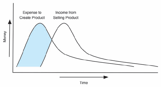
Business Goes Where Money Flows
In a business based on product sales, there is a gap between expense and income. Money is spent during product creation, but income does not begin to arrive until the product is available in the market. This situation is depicted in the following graph, with the shaded area representing the initial outlay of capital required for product development.
If traditional development practices are used, additional products will have similar expense/income curves, like so:
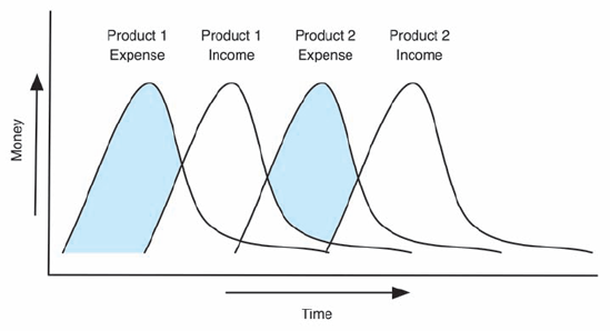
The use of product lines, however, lowers the development cost and time for making a new product in the product line. In doing so, additional revenue can come in earlier, reducing the effect of expenses that are incurred, like so:

Note that the shaded areas (times when expenses exceed revenues) are much more limited when product lines are used.
Products in an engineering product line are tied together by similarities in how they are designed or constructed. Often, a product line will be both a business and engineering product line, but this is not always the case. For example, an auto manufacturer, such as Ford, will build a number of cars on the same engineering platform but market them under different brand names, such as Lincoln, Mercury, and Mazda. Engineering product lines often share significant portions of their architecture, and the products within them may all conform to a broader DSSA. The product lines discussed in the remainder of this chapter are engineering product lines; however, Section 15.2.10 discusses strategies for unifying disparate products (perhaps those in a business product line) into an engineering product line.
The architectures of product lines are somewhat different from reference architectures in a DSSA. In general, product-line architectures capture the complete architectures of multiple related products simultaneously. Conversely, reference architectures can be incomplete or partial. They may, for example, specify the architecture of a single product with loose guidance about how to adapt it to other contexts. They may also specify only invariant parts of an architecture and leave the rest up to solution developers.
Product-line architectures differ from reference architectures in two ways. The first difference is one of scope: Rather than attempting to describe the architectures of many (potentially diverse) solutions within a domain, product-line architectures focus on a specific, explicit set of related products, often developed by a single organization. The second difference is one of completeness: Product-line architectures generally capture multiple complete product architectures rather than leaving parts undefined.
Recall our characterization of architecture as the set of principal design decisions about a system. A product-line architecture can be similarly defined: A product line architecture captures simultaneously the principal design decisions of many related products. Some of these design decisions will be common among all the products, some will be common among a subset of the products, and some will be unique to individual products.
Figure 15-21 shows a product-line architecture with two products conceptualized as a Venn diagram. The large center circle represents the design decisions common to all products in the product line. The "A" shape represents the decisions that are unique to Product A. The "B" shape represents the decisions that are unique to product B. Figure 15-21(a) shows the three groups of design decisions. Figure 15-21(b) highlights Product A: the union of the common design decisions and the "A" design decisions. Figure 15-21(c) shows Product B: the union of the common design decisions and the "B" design decisions.

To further discuss product-line architectures, we turn again to the Lunar Lander example. We have discussed different variants of the Lunar Lander game in earlier chapters, but each has been discussed in isolation. Product-line architectures give us the power to specify and discuss a family of Lunar Lander games in terms of explicit differences among the family members. The constructs that make this possible are variants and versions.
Extending an ordinary software architecture into a product line architecture can be accomplished through the addition of variation points to create variant architectures. Each variant architecture represents a different product—a member of the product line. A variation point is a set of design decisions that may or may not be included in the architecture of a given product. Variation points identify where the design decisions for a specific product architecture diverge from the design decisions for other products. Each variation point is accompanied by a condition that determines when the design decisions for that variation point are included in a product's architecture. In the above example, the inclusion of the "A" design decisions can be seen as a variation point. The condition for this variation point is simple: The decisions are only included if the product being built is Product A.
By isolating and codifying variation points, a large number of product architectures can be described compactly by exploiting the different combinations of variations. Consider a hypothetical product line of Lunar Lander games that consists of three slightly different Lunar Lander products: Lunar Lander Lite, Lunar Lander Demo, and Lunar Lander Pro.
Lunar Lander Lite is intended as a freely distributed Lunar Lander game with a text-based user interface. It resembles the Lunar Lander games discussed in earlier chapters, such as those implemented in Chapter 9. Lunar Lander Pro is intended as a commercially sold Lunar Lander game with a fancier graphical user interface. Internally, the data store and game logic are identical to Lunar Lander Lite's; the only difference is in the user interface component. Lunar Lander Demo is a freely distributed but time-limited version of Lunar Lander Pro. It has the same graphical user interface as Lunar Lander Pro, but it expires and is not playable thirty days after installation. Periodically, it reminds users that if they want to continue playing beyond the thirty-day limit, they are required to purchase or upgrade to Lunar Lander Pro.
The architectural structures of all three Lunar Lander products are shown in Figure 15-22.[21] Figure 15-22(a) shows Lunar Lander Lite, consisting of a data store and game logic component, along with a text-based UI. Figure 15-22(b) shows Lunar Lander Demo, with a graphical UI component in place of the text-based UI, and an additional demo reminder and system clock that plug into the user interface to remind the user to register. Figure 15-22(c) shows Lunar Lander Pro, identical to Lunar Lander Demo but missing the Demo Reminder and System Clock components.
Table 15-1 shows the elements—in this case components and connectors—included in each of the three product-line members. This kind of table is good for deciding whether and how to create a product line. Here, it is obvious that there is significant commonality and overlap among the three products—good motivation for creating a product line.

Once the creation of a product line begins, it is a good idea to group low-level elements into variation points. Recall that each variation point represents a set of design decisions that may or may not be included in the architecture. This allows product-line architects to think about products in terms of features rather than low-level elements. For example, while it is conceivable to think of a product that contains a System Clock Connector but no System Clock, in practice this does not make much sense.
Table 15-1. Elements present in each Lunar Lander product-line member.
Product | |||
|---|---|---|---|
Components and Connectors | Lite | Demo | Pro |
Data Store | X | X | X |
Data Store Connector | X | X | X |
Game Logic | X | X | X |
Game Logic Connector | X | X | X |
Text-Based UI | X | X | |
UI Plug-Ins Connector | X | X | X |
Graphical UI | X | X | |
System Clock | X | ||
System Clock Connector | X | ||
Demo Reminder | X | ||
Table 15-2. Grouping architectural elements into variation points.
Components and Connectors | Core Elements | Text UI | Graphical UI | Time Limited |
|---|---|---|---|---|
Data Store | X | |||
Data Store Connector | X | |||
Game Logic | X | |||
Game Logic Connector | X | |||
Text-Based UI | X | |||
UI Plug-Ins Connector | X | |||
Graphical UI | X | |||
System Clock | X | |||
System Clock Connector | X | |||
Demo Reminder | X |
A mapping of elements to variation points is shown in Table 15-2. Here, elements common to all products are grouped into Core Elements. Three other variation points are defined as well: the inclusion of a textual UI, a graphical UI, and whether or not the product is time-limited. The grouping of architectural elements or design decisions into features is often motivated by domain constraints, business goals, and the individual dependencies and exclusion relationships among the elements. Ultimately, these groupings must be chosen and defined by system architects—their creation is not an algorithmic process. Variation points will have dependencies and exclusion relationships as well: For example, all variation points depend on the inclusion of the Core Elements, and at least one of the two user interface variation points must be included in a product. These relationships and constraints must be carefully documented.
Once the variation points have been defined, individual products can be specified as combinations of the variation points. For business reasons, or reasons of variation point compatibility, not all combinations of variation points will be made into products.
Table 15-3 shows the creation of the three Lunar Lander products from the variation points defined in Table 15-2. Assuming that the core elements are always included, the three variation points altogether create 23 or eight potential products, of which three have been selected for construction. In addition to helping people understand the differences between the different product-line members, this kind of table is often useful in generating ideas for new products using the variation-point combinations not selected. For example, one could conceive of a Lunar Lander game that includes both a textual and a graphical user interface, perhaps giving the user multiple ways of interacting with the game and viewing its state. One could also imagine a time-limited version of the game with a textual UI, or a time-limited version with both user interfaces.
Table 15-3. Products as combinations of variation points.
Lunar Lander Lite | Lunar Lander Demo | Lunar Lander Pro | |
|---|---|---|---|
Core Elements | X | X | X |
Text UI | X | ||
Graphical UI | X | X | |
Time Limited | X |
By unifying common features and documenting these explicit variation points, we can combine these three individual architecture descriptions into a single product-line architecture. A few architecture description languages such as Koala (van Ommering et al. 2000) and xADL (Dashofy, van der Hoek, and Taylor 2005) allow you to do this directly.
The combined product line is shown in Figure 15-23, here in xADL's graphical visualization using xADL's product-line features (Dashofy and van der Hoek 2001) to express the points of variation. All elements from all products are shown together. Elements such as the Data Store and Game Logic components that are part of the core are represented normally. Elements that are included in one or more variation points are represented as optional. Each optional element is accompanied by a guard condition that indicates when it should be included in a product. In this product line, three variables—includeTextUI, includeGraphicalUI, and timeLimited—correspond to the variation points defined in Table 15-2. By setting the value of any of these variables to "true," the elements corresponding to that variation point will be included in the architecture.

xADL's use of a Boolean expression language to document these guard conditions gives it additional expressive power, including some ability to constrain relationships between features. For example, the Text-based UI and Graphical UI features could be made mutually exclusive by unifying the includeTextUI and includeGraphicalUI variables into a single variable, say 'uiType,' whose value would be either "graphical" or "textual," but not both.
The process of reducing a product line into a smaller product line or a single product is known as selection. Selection involves evaluating the conditions associated with each variation point and either including or excluding the associated design decisions.
Consider the Lunar Lander product line. By fixing the includeTextUI variable to "false," we have selected only products that do not include a textual UI. This reduces the total number of potential products from 8 to 4. By also fixing "includeGraphicalUI" to "true," we can select only those products that include a graphical UI. Now, the total number of potential products is two. By fixing the final variable, timeLimited, to "true," we can reduce the product line to a single product—one without a textual UI, with a graphical UI, and that is time-limited. This product, incidentally, is the Lunar Lander Demo product—something easily seen by referring to Table 15-3.
Without tool support, product-line selection must be performed manually—either on the fly in the minds of the stakeholders interpreting architectural models or by creating and maintaining explicit models of each product in the product line. Using an approach that supports the explicit specification of variation points and product lines such as Koala or xADL can make the selection process substantially easier. Specifically, in these approaches product-line selection can be performed automatically through the use of tools. xADL's product-line selector tool allows users to bind values to guard variables, and then reduce a product-line architecture such as the one shown in Figure 15-23 into a single-product architecture such as the one shown in Figure 15-22 with a few clicks of the mouse.
The products in a product line are often alternatives to one another, intended for simultaneous development and release, as is the case with the Lunar Lander product line described above. However, product-line architectures also can be used to capture different versions of the same product over time. In general, different versions of the same product will have relatively similar architectures (unless something drastic such as a complete redesign or rewrite occurs). When this is the case, it is possible to enumerate the design decisions in both architectures and determine what changed from one version of a product to the next. These can be turned into variation points and encoded into a product line, where the different products are not alternatives, but rather the same product at different times.

Consider an evolving Lunar Lander game. The first version of the game might include a graphical user interface with two-dimensional graphics. A second version of the same game might differ by including a graphical user interface with three-dimensional graphics, supported by an off-the-shelf three-dimensional rendering engine. These two product architectures are shown in Figure 15-24(a) and (b), respectively.
Clearly, this situation mirrors the situation seen earlier when the products were different games to be marketed, rather than versions of the same game. Using the same mechanisms described above, the two versions of the game might be encoded into a single product line, with each product representing one version of the game. This product line is shown in Figure 15-25. Here, the version is selected using a single variable, version, rather than by choosing a combination of variation points.
Product lines can be used to capture variations across related products and across different versions of the same product. Another application of product lines is to capture design alternatives. Design is often an exploratory process—it involves making decisions and trade-offs that will affect the properties and construction of the target products. Questions arise: Should we include this component or that component? Should this part of the application run on the client or on the server? Often, it will be unclear which path is best, so multiple alternatives are considered and pursued until more information becomes available.

When this happens, product-line techniques can be used to simultaneously capture alternative architectures. Here, each product is not a system that is intended to be built, but one of many potential product designs. Points of variation in these product lines are decision points. The selection process can be used as a form of "what-if" analysis.
The major reductions in implementation costs from using a product line come about primarily through extensive reuse: Where two products in a product line share a similar architecture, the implementations should be (virtually) identical. Achieving this level of reuse must start in the architecture. Here, flexibility in connectors and communication methods is a primary driver of product-line reuse. If an architecture is chosen where components and connectors are tightly bound, it will be extremely difficult to introduce points of variation without recoding existing components. However, if flexible connectors and communication styles (such as message passing) are used instead, it is easier to introduce variations in the architecture without making extensive changes. However, having flexibility at the architectural level does not necessarily mean that the same flexibility will be present at the implementation level.
Chapter 9 discussed how implementing a system built using software architecture techniques is largely a mapping problem: understanding and controlling how design decisions made in the architecture map to implementation artifacts. In general, all the advice in Chapter 9 applies here as well. Implementing a product-line architecture is still a mapping problem, except that multiple products composed of core elements and variation points are involved. In this case, separating concerns in the implementation artifacts along the boundaries of variation points in the product line is critical.
Consider the situation presented in Figure 15-26. In Figure 15-26(a), good separation of concerns has not been maintained in the implementation. Various source files (File1.java, File2.java, and File3.java) are responsible for implementing both core and product-specific concerns. In this case, neither Product A nor Product B can be constructed without importing at least part of the implementation of the other. This makes it hard to evolve the products independently, and to integrate new products into the product line. Figure 15-26(b) shows a good separation of concerns: Here, implementation artifacts corresponding to products are kept separate from the common core and from each other. Both products can be built without using artifacts that (partially) implement other products.
One way of maintaining this separation of concerns is to use flexible architecture implementation frameworks, as discussed in Chapter 9. Many implementation frameworks help to enforce loose coupling between component and connector implementations, such that components and connectors can have their dependencies changed easily and automatically. Implementation frameworks often allow components and connectors to be bound to each other "late"—either at product build time or even dynamically at run time. Implementations that employ late bindings of components generally enforce better separation and independence of components and help to drive reuse. Interface-implementation separation is also important: Well-defined implementation-level interfaces help to establish the services that are provided and required by a component (or set of components) without requiring a particular implementation. This separation of concerns further increases flexibility: Changes to the implementation of one component will not require changes to other components if the contract of the interface is maintained.
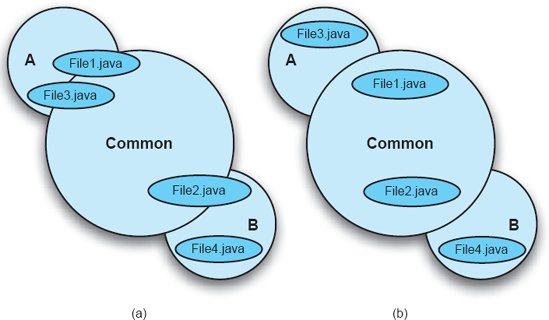
Figure 15-26. Maintaining separation of concerns when implementing a product-line architecture: (a) bad and (b) good.
This is not always easy to achieve. Often, legacy products are incorporated into a product line. These products may not use flexible components, connectors, and communication methods. In this case, a careful refactoring should be considered, driven by the product-line architecture. Tight bindings in a product line are workable as long as they do not interfere with or cross the points of variation. For example, if three core components that are part of every product in the product line are tightly coupled, this is not a major problem: These components never will be separated, so making their bindings to each other flexible will be of limited near-term value. Instead, developers and architects should focus on making the bindings to components that exist only in a few products more flexible.
Any mature development project will leverage some form of configuration management tool set to keep track of different versions of lower-level implementation artifacts: code files, resource files, and so on. Successfully managing product-line implementations requires an understanding of the relationship between versions of architecture-level elements (components, connectors) and versions of implementation-level elements (code, resource files) as stored in a configuration management repository. Implementations that are cleanly separated along the lines of architectural elements greatly simplify the mapping problem.
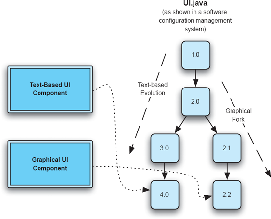
Figure 15-27. Dealing with versions and development branches in a configuration management repository.
One phenomenon that occurs more often in product-line development than in single-product development is the use of multiple versions of the same implementation artifact (for example, source file) in different places in the product line architecture. For example, recall the Lunar Lander product line shown in Figure 15-23. Perhaps, for whatever reason, the implementation of the text-based user interface and the graphical user interface were based on the same code, a single file called UI.java, that has evolved over time. At some point in the past, a fork of UI.java was created in the configuration management repository, without renaming the file. Thus, there are two development branches of UI.java: one for a textual UI and one for a graphical UI.
This situation is depicted in Figure 15-27. Here, the Text-Based UI component uses version 4.0 of UI.java, while the Graphical UI component uses version 2.2. In a situation like this, implementation mappings must not only refer to individual files, but also individual versions of individual files.
Unfortunately, product lines are not always considered at the inception of a group of related products. The idea of using product lines often appears on an organization's radar only after it has developed many products that have similar functionality and has duplicated an enormous amount of effort in doing so. Alternatively, company mergers and acquisitions can leave a single organization with the responsibility for developing, maintaining, and evolving very similar (and at one time, competing) products. At this time, the use of product lines becomes extremely attractive as a way of cutting costs by reusing engineering knowledge and architectural decisions from one product to the next. The difficulty is that the existing products in the product line often share little intellectual heritage, and the product architectures differ widely.
This is one of the most difficult problems in product-line development. The primary tension is that the goal of using a product line is to enable reuse, but the existing products exhibit little to no reuse. When this is the case, attempting to develop a product-line architecture that includes all the existing products may be of limited value, except as a historical artifact. Instead, processes should be forward-looking, attempting to extract the architectural lessons of previous projects and unify them into a product line for future products (or future product versions).
Before a product-line architecture can be developed, individual product architectures must be obtained. Architecturally savvy organizations already will have documented architectures for their products, but, as we have discussed, many product architectures evolve organically or diverge from their original intentions. In this case, architectural recovery (discussed in Chapters 3 and 4) is the first step toward product-line development.
The next step of the process is to normalize the existing product architectures (if necessary). Often, even when architectures for each product are available, they may not capture the same aspects of the systems under development, or capture those aspects at the same level of detail. They may not use the same terminology to refer to similar concepts. When this is the case (and it nearly always is) some amount of normalization must occur—some of the architectures must be adapted so that the commonalities and differences among the product architectures can be more readily identified. Luckily, architecture elaboration in this situation is made easier by the fact that there are actual, implemented products from which to extract the additional necessary information.
When normalized product architectures are available, they can be compared to identify common aspects and points of variation. Unless all of the architectures are expressed in the same notation at the same level of detail, it is probably not possible to automate much of this process. Instead, it is more useful to gather the architects and other stakeholders from each product into a series of meetings. Developing tables similar to Table 15-1 and Table 15-2 in order to understand the overlap between features and elements in the various products may be a useful exercise.
Developing a product-line architecture from this point forward is then a stakeholder-centric activity. There is no one right way to go about this, and depending on the domain and the organizational goals, the effort may go in one of many different directions:
No Product Line: It may be determined that, after examining the architectures, less reuse is possible than previously imagined. Perhaps the products were thought to perform many similar functions, but in reality they do not. Alternatively, the products may be so architecturally different that attempting to unify future versions of the products into a product line would cost more than the potential reuse would save. Here, the best alternative might be to abandon the idea of developing a product line entirely, and focus on further distinguishing the products from one another in separate development efforts.
One Master Product: Often, the easiest course of action in developing a new product line is to identify the best existing product and use its architecture as a basis for a product line. In this way at least one product will fit naturally into the emergent product line, and innovative features from other products can be integrated as appropriate.
Hybrid: When no one product can be identified as the master for the purpose of developing a product line, the "best of breed" features of each product in the domain can be extracted and unified into a hybrid product line. Here, no one existing product will fit totally naturally into the product-line architecture. This is most useful when new products are not intended to be direct descendants of old products or when existing products are being unified.
This chapter has largely covered the creation and management of product lines and product-line architectures from a technical perspective. However, using product lines is not a solely technical activity. A product-line–based approach needs to be as much organizational and cultural as it is technical. Creating a product line often means integrating the needs and opinions of stakeholders from fundamentally different perspectives into the same effort. This can foster all kinds of organizational and technical issues: friction between the teams, feature creep, difficulty prioritizing customers, least-common-denominator architectures, and so on.
Furthermore, an organization's investment strategy in its products needs to change to match a product-line approach. Creating a product line incurs substantial costs that do eventually pay off, but not in the context of a single product. Rather, they are recovered through lower maintenance expenses across multiple products, the increased profits from selling more product variants, and the lower costs of developing future versions of the products. This requires organizations to think horizontally, across product and team boundaries, which often requires both an organizational and cultural shift.
Paul Clements and Linda Northrop have written extensively about these issues in their book Software Product Lines: Practices and Patterns (Clements and Northrop 2001); we encourage those interested to look to this and other sources for more detailed guidance in this regard.
We have discussed domain-specific software architectures (DSSAs) and product lines, as well as their relationship to each other. A natural question arises at this point: What are the relationships among DSSAs, product lines, and architectural styles?
Recall that architectural styles represent a reusable package of design decisions that can be applied to different products to elicit desired qualities. In some sense, both DSSAs and product-line architectures can be seen in the same light. Usually, however, architectural styles are far more general than DSSAs or product lines. Most architectural styles can be applied across many domains. For example, the pipe-and-filter style has been used to develop text-processing applications, typesetting systems, and program compilers. Typically, such diverse applications would not all be members of the same DSSA or product line.
Styles do, however, play an important role in the development of both DSSAs and product lines. It would be unusual for different products in the same DSSA or product line to have significantly different architectural styles. As noted above, one of the most common canonical requirements in the development of a DSSA is the architectural style that will be used to create applications within the DSSA. Typically, a reference architecture for a DSSA will follow this prescribed style. Similarly, individual products in the same product-line architecture will generally follow the same style. The use of a common style across a DSSA or product line is ultimately an effort to ensure consistent qualities in the products that emerge and to keep them from drifting away from the original intent of the product line.
Just as there can be points of variation in architectures, there can also be points of variation in architectural styles themselves: different sets of constraints to solve related problems. By applying product-line architecture techniques to the decisions that compose architectural styles rather than architectures, it is possible to create a family of architectural styles.
Recall two of the most basic architectural styles from Chapter 4: batch-sequential and pipe-and-filter, as shown in Figure 15-28. These styles actually have many constraints in common. For example, both enforce a linear ordering of components, each of which has one input and one output, and data moves unidirectionally through the line, being processed individually by each component. They differ in a few details: batch-sequential systems pass the data wholesale in a chunk, and only one component operates on the data at a time; pipe-and-filter systems pass data as it is available and components execute in parallel when possible. Here, explicit variation points can be used to express and reason about the relationship between architectural styles just as they are used to reason about the relationship among software products.

We now present two examples of how domain-specific software engineering techniques, including product-line architectures, have been applied in software development practice. The first example is Philips Electronics's use of the Koala architecture description language in the development of software for devices in the consumer electronics domain. The second example is the domain of software-defined radios, configurable devices that communicate using radio waves, with their internal functionality implemented by software.
Consumer electronics is a dynamic and highly competitive domain of product development. For decades, devices such as televisions and cable descramblers were relatively simple with a few, well-defined capabilities. Over the years, they have become more and more complex, largely due to enhancements in their embedded software. The latest incarnations of these devices include graphical, menu-driven configuration, on-screen programming guides, video on demand, and digital video recording and playback. In a global marketplace, each of these devices must be deployed in multiple regions around the world, specifically configured for the languages and broadcast standards used in those regions.
The increasing feature counts of consumer electronic devices are accompanied by fierce competition among organizations, and it is just as important to keep costs down as it is to deploy the widest range of features. From a software perspective, keeping costs down can be done in two primary ways: limiting the cost of software development and limiting the hardware resources required by the developed software. Additionally, manufacturers often multisource certain parts. That is, they obtain and use similar parts (chips, boards, tuners, and so forth) from multiple vendors, buying from vendors who can offer the part at the right time or the lowest price, and providing a measure of insurance against the failure by one particular part vendor to deliver. If the parts are not 100 percent interchangeable, software can be used to mask the differences.
Product-line architectures provide an attractive way to deal with the diversity of devices and configurations found in the consumer electronics domain. Philips Electronics developed an approach called Koala (van Ommering et al. 2000) to help it specify and manage its consumer electronics products. Koala is primarily an architecture description language (derived from the Darwin ADL). Koala also contains aspects of an architectural style since it prescribes specific patterns and semantics that are applied to the constructs described in the Koala ADL. Koala, like Darwin, is effectively a structural notation: It retains the Darwin concepts of components, interfaces (both provided and required), hierarchical compositions (components with their own internal structures), and links to connect the interfaces. In addition to these basic constructs, Koala has special constructs for supporting product-line variability. Koala is also tightly bound to implementations of embedded components: Certain aspects of Koala (such as the method by which it connects required and provided interfaces in code) are specifically designed with implementation strategies (such as static binding through C macros) in mind.

A basic Koala diagram with no product line variability for a Lunar Lander application is shown in Figure 15-29. As you can see, basic Koala diagrams are effectively equivalent to Darwin diagrams. Koala extends Darwin in the following ways:
IDL-based interface types: An interface type in Koala is a named set of function signatures, similar to those you would find in C. For example, the interface to the Lunar Lander data store in Koala might be declared like this:
interface IDataStore{
  void setAltitude(int altitudeInMeters);
  int getAltitude();
  void setBurnRate(int newBurnRate);
  int getBurnRate();
  ...
}
The
IDataStoreinterface type may be provided (or required) by any number of Koala components. When a provided and required interface are connected, the provided interface type must provide at least the functions required by the required interface type.Diversity interfaces: One of the philosophies of Koala is that configuration parameters for a component should not be stored in the component; instead, configuration parameters should be accessed by the component from an external source when needed. This allows the application to be configured centrally, from a single component (or set of components) whose purpose is to provide configuration data for the application. Diversity interfaces are special required interfaces that are attached to components and are used by the component to get configuration parameters.
Switches: A switch is a new architectural construct that represents a variation point. It allows a required interface to be connected to multiple different provided interfaces. When the variation point is resolved, only one of the connections will actually be present. A configuration condition determines which provided-required interface pair is connected. These configuration conditions are analogous to the guards discussed earlier in this chapter. A switch is connected to a diversity interface to get its configuration parameters, just as a component would. Depending on the values returned through the diversity interface, the switch will route calls to one of the required interfaces connected to it. This may result in disconnected components (that is, components that will never be involved). Disconnected components are not instantiated to save resources.

Figure 15-30 shows a Lunar Lander architecture in Koala with a variation point. Here, the application can use an in-memory data store or a relational data store to maintain application state. The required interface of the Game Logic component is now routed through a switch, which is configured by configuration parameters provided externally. The Game Logic component includes a new diversity interface div that allows it to access those external configuration parameters.
Several components may provide similar, but not identical, services. For example, a basic TV tuner component may have only the ability to change frequencies, but an advanced TV tuner may be able to search for valid frequencies as well. It is possible for callers to a TV tuner to include an optional required interface and query whether the interface is actually connected or not. If it is connected, the caller can make calls on the optional interface; if not, the caller should behave/degrade gracefully.
Through these mechanisms, Koala gives architects the power to specify and implement product lines of embedded systems. Koala's main strengths are its straightforward notation, intuitive graphical visualization, and tool support for implementing product lines efficiently. Although developed for the consumer electronics domain, Koala is generic enough for use in many domains.
A drawback of Koala is its lack of support for explicit software connectors (a trait it inherits from Darwin). Koala implies that communication among components happens exclusively through synchronous request-response procedure calls. There is no explicit support for asynchronous or message-passing interaction (message passing, in particular, is a well-known mechanism for supporting flexibility and diversity). However, in the target domain (embedded systems in consumer electronics devices), synchronous procedure calls are a very typical mode of interaction.
Using an architecture-centric approach gave Philips the ability to break up its software systems into reusable components that communicate through explicit interfaces, while still retaining the small size and efficiency necessary for embedded systems development. Taking inspiration from an existing architecture description language (Darwin), Philips defined a domain-specific ADL (Koala) with semantics that mapped well to its application domain. Additionally, Philips incorporated explicit support for variability into Koala. This gave it the ability to deal with the many market-induced variations in its product lines (to deal with multiple grades of products with different feature combinations, different requirements due to internationalization, and so on). Rather than maintaining separate architectural descriptions for each product, entire product lines can be captured in a single model. More than 100 engineers at Philips have used Koala, making it one of the most successful industrial applications of ADLs and domain-specific architecture-centric development.
Communication over the air has been used to facilitate all kinds of social advances, from early audio and Morse-code transmissions to video transmissions for television, to the latest advances in cellular phones and broadband WiFi connections. Traditionally, radio hardware has been specialized for a particular kind of application: For example, an ordinary car stereo is limited to receiving analog AM/FM audio transmissions. It cannot, for example, decode TV signals (even the audio portion) or act as an Internet WiFi repeater. To do so would require hardware components to be changed out or adapted.
The increased capabilities of digital signal processing components as well as advances in reconfigurable hardware[22] in particular) have made it possible to rethink how communication-over-radio devices are built from both a hardware and software perspective. The result has been an effort to develop so-called software-defined radios (SDRs) (Dillinger, Madani, and Alonistioti 2003). A software-defined radio is a device that can transmit, receive, and process signals over the air for a variety of applications, where the application is defined by the software that is loaded on the radio. Standard components of a software-defined radio include an antenna, analog-to-digital conversion, FPGAs for high-frequency digital signal processing, and general-purpose processors (such as PowerPCs) for further signal processing duties, as well as various I/O ports for interfacing with audio and video devices (displays, microphones, speakers, and so on).

The basic data flow through a hypothetical software-defined radio board is shown in Figure 15-31. Depending on the configuration of the FPGA(s) and the components and connectors loaded on the general-purpose processors, the radio can be used for all sorts of applications. In theory, a software-defined radio could act as everything from an ordinary FM radio to a television set to a wireless access point simply by loading different software onto the radio.
The domain of software-defined radios is ideal for the application of DSSE principles. A domain-specific software architecture has been developed for software-defined radios called the Software Communications Architecture (Modular Software-programmable Radio Consortium 2001); see the accompanying feature titled, "The Software Communications Architecture (SCA)." This particular DSSA is not a panacea, however, and the sidebar touches on many issues that may make it less than ideal.
The software-defined radio domain is also an example of where product lines can make a significant impact because the domain encompasses so much variability. Variability exists at many different levels of abstraction:
Network Topology: In this domain, radio devices do not stand alone: They communicate (via radio links) with other radios running other applications. Although software-defined radios can remain in one location, it is often the case that the radios themselves are mobile—mounted to vehicles or carried by individuals who move around. As such, the topology of devices can change as they move around or devices go on or offline.
Radio Configuration: A single software-defined radio board comprises a channel: a device that can be configured for one particular application at a time. In general, these devices are configured on a single board. More complicated radios support multiple channels by having multiple hardware boards mounted in the same radio backplane. Two-to-eight–channel radios are not uncommon for commercial or military applications.
Board Configuration: Each board in a software-defined radio can be implemented in a number of different ways. Although the basic elements (antenna, analog-to-digital conversion, and signal processing) are basically the same, they can be configured in different ways. Boards may include different FPGAs, different general-purpose processor configurations, different I/O ports and controllers, or different amounts of memory or storage.
Software Configuration: Each board generally has a number of processing elements on it that can be loaded with software: FPGAs and general-purpose processors, for example. Depending on the application, different components will be loaded onto the different processing elements.
Variability at each of these levels must be understood, controlled, and managed. The first thing to note is that these levels of abstraction are more or less hierarchical: Vehicles contain radios, radios contain boards, boards contain processing elements, and processing elements contain software elements. Modeling notations that directly support hierarchical architectures, such as Darwin, Koala, or xADL 2.0, are all good candidates for modeling such an architecture. Variability at each level is also somewhat limited: Specific software-defined radios will be developed for specific purposes (military, commercial, and so on). Thus, network topologies will have certain common characteristics. For a given organization, only a few different radio and board configurations will be produced: An organization may produce only a two-channel and a four-channel radio, for example. Board configurations may be limited to a "test board" and a "production board." Software configurations will be partially driven by board configuration: Each device or controller on the board will likely have an associated device driver component; other components will be driven by the various applications loaded on the radio.

Figure 15-32. Software-defined radio structure with (a) just drivers and operating environment loaded, and (b) with a waveform application deployed.
Figure 15-32 shows two variants of the architecture of a software-defined radio called the SCA Reference Implementation (SCARI), modeled in xADL and depicted in xADL's graphical visualization. SCARI is a simple example of an SCA-based software-defined radio, intended to demonstrate how the SCA can be used to implement an SDR. Figure 15-32(a) shows the radio with only the device drivers and operating environment deployed. Figure 15-32(b) shows the same radio with an additional waveform application deployed. Each represents a different product-line variant, and by assigning guards to each the waveform components using techniques shown earlier in this chapter, waveform deployments can be selectively applied to the radio using product-line selection.
The extreme flexibility in the domain is induced by increasingly adaptable hardware, but is primarily enabled by software. Since software is so malleable, this should come as no surprise. Because of this, as well as other constraints that must be considered when dealing with SDRs—size, power consumption, performance, time to load and unload waveforms, and so on—SDRs are yet another domain where the capture and reuse of specialized engineering knowledge and experience can substantially reduce costs and risks in the development of new systems.
Domain-specific software engineering is, in many ways, the culmination of all the advice given in this book. It broadens the challenge of architecture-based development substantially: Instead of just applying architecture-centric principles to a single product, organizations and even entire communities must apply them across a range of related products. This is complicated by the fact that the products already developed in the domain were developed for different, often competing business goals, by isolated development groups that did not share engineering knowledge or architectural assets. This is perhaps the biggest challenge in architecture-centric software development, but it also has the greatest potential reward: a substantial reduction in costs and risks to develop new systems within an entire domain.
In some ways, the creation of a domain-specific software architecture resembles the development of an architecture for a single product—it still involves modeling, visualizing, analyzing, and applying principal design decisions. However, it is made even more difficult by the fact that the architecture must work for a wide range of systems. A constant tension exists between overspecification and underspecification—specifying too much and constraining the kinds of systems you can construct versus specifying too little and providing insufficient guidance and value. Key contributors may come from different backgrounds and organizations and may have fundamentally different ideas about how the architecture should be constructed. This chapter has provided a survey of the kinds of artifacts that make up a domain-specific software architecture, and provided some advice about how to create them. However, in the end, it still is a very human-centric process of negotiation and cooperation.
Product-line architecture techniques provide a more concrete way to apply domain-specific software engineering "in the small." Product lines are typically developed within a single organization and target a much narrower set of products. Because of this narrower focus, product-line architectures are often far easier to develop and maintain than DSSEs, since there is far less variation in business goals and there are fewer organizational boundaries to cross. Substantial cost reduction and risk mitigation can still be achieved within the product line, especially if automated tools can help with activities such as product-line selection.
Domain-specific software engineering highlights how software architecture in practice is both an organizational and a technical issue. We have highlighted how business concerns motivate certain development practices and techniques. The next chapter will continue this theme by focusing on architecture-related standards. The creation, adoption, and use of standards are also driven by business goals, and standards are a big part of how software architecture is viewed and used in practice.
What is domain-specific software engineering (DSSE)? What problems in software development does it address?
What are the three main concerns addressed by DSSE? How do they relate to one another?
How does DSSE help to partition problem spaces and solution spaces? How does this make software development easier?
Enumerate the various artifacts that are part of a DSSA. What information does each artifact contain? What is its purpose?
What is a reference architecture? How does it differ from an ordinary software architecture? What different kinds of reference architectures can be created?
When should a reference architecture be developed?
What is a product line? How does it differ from a domain?
What is a product-line architecture? What is the relationship between a reference architecture and a product-line architecture? What are variation points?
Identify strategies for unifying multiple related products into a product line.
What is the relationship between architectural design decisions, features, and products in a product line?
How can product lines be used to capture variations in a single product over time?
How can product lines be used to capture what-if scenarios in product development?
What is product-line selection and how is it performed?
What are some strategies for unifying products with different intellectual heritages into a product line?
What is the relationship among DSSAs, product lines, and architectural styles?
How does Koala assist developers in domain-specific software engineering? What Koala features enable it to capture product-line architectures?
How can domain-specific software engineering techniques help in the construction of software-defined radios? How can software-defined radios form a product line?
Select a problem domain with which you are familiar and try to produce a domain model as described above. Which of the domain modeling activities pose the greatest challenges? Why?
Survey some of the architecture-based development approaches presented in this book, and identify how (or if) they address the three primary concerns of domain, business, and technology. Is any one concern favored over others? Why?
Find two to four examples of systems that are in the same domain but are not built by the same organization. Create tables, like those in this chapter, showing the elements in each product, grouping them into features, and showing how features are composed into the products. Speculate on how you might use DSSE and product-line techniques to unify these products into a product line, or to extract a DSSA from them.
Use an architecture description language that supports product-line modeling such as Koala or xADL to capture at least three different Lunar Lander games with different features.
Download and review the SCA specification. Which aspects of a DSSA are covered by this specification and which are not? Is it an adequate reference architecture for the domain of software-defined radios?
Find an open-source project that has multiple product variations—perhaps for reasons of running on different platforms, providing different services, or working in an international context. Determine how these product variants are managed. Is an architectural approach at work?
A tremendous amount of the general DSSE/DSSA information in this chapter comes from early work on domain-specific software engineering in the avionics domain by Will Tracz and Don Batory et al. (Tracz 1995; Tracz 1993; Tracz, Coglianese, and Young 1993; Tracz 1996; Batory, McAllester et al. 1995; Batory, Coglianese et al. 1995; Tracz, Coglianese, and Young 1993). These references not only provide deeper background on DSSE and DSSAs in general, but also discuss yet another application domain in which these techniques have been applied. Tracz has also written extensively on reuse in general, with most of his articles compiled into his book Confessions of a Used Program Salesman (Tracz, 1995).
The Koala (van Ommering et al. 2000) work is another excellent example of the successful use of architecture-centric development in practice. Although the early Koala work was focused on individual product lines, Rob van Ommering has expanded his work to cut across product lines and address product populations (van Ommering 2002) as well.
There is extensive literature on product lines. Paul Clements and Linda Northrop (Clements and Northrop 2002) write about product lines from a high-level perspective, focusing on management issues, processes, patterns of practice, and case studies. Hassan Gomaa (Gomaa 2004) takes a UML-centric approach to modeling both product lines and patterns found therein. Klaus Pohl et al. (Pohl, Böckle, and van der Linden 2005) also take a primarily process-centric approach.
Another substantial body of work on product-line architectures and modeling comes from Andrévan der Hoek et al. in the Ménage project (van der Hoek 2000; Roshandel et al. 2004; van der Hoek 2004), which captured options, variants, and versions explicitly in architectural models and which inspired the product-line features in xADL.
[20] The feature model is sometimes also referred to as "context model," and the feature relationship diagram as "context diagram." We deliberately refrain from using "context" in this setting to avoid confusing matters with the context diagram in the information model.
[21] The Lunar Lander example in this chapter will focus on structural design decisions; however, the techniques described apply, in general, to broader kinds of design decisions that go beyond just components and connectors.
[22] FPGA stands for Field Programmable Gate Array. An FPGA is effectively an integrated circuit consisting of an array of logic gates that can be reconfigured through software. Once reconfigured, the circuit can perform any function it is programmed for—processing data, cracking encryption, emulating a microprocessor, and so on. In general, FPGAs are slower and larger than special-purpose hardware, but the performance is reasonably close.