
Rigorous models of software architectures present a number of advantages over informal boxes-and-lines diagrams. They force the software architect to address issues that might otherwise be missed or ignored. They allow more precise communication among the system's various stakeholders and form a solid blueprint for the system's construction, deployment, execution, and evolution. And they typically present more detail about the architecture than do informal models, so that more questions can be asked and answered more precisely—although there are certainly times where sufficient understanding about certain aspects of a system can be obtained even from informal models.
Definition. Architectural analysis is the activity of discovering important system properties using the system's architectural models.
Getting early, useful answers about relevant aspects of the system's architecture can help identify inappropriate or incorrect design decisions before they are propagated into the system, thus reducing the risk of system and project failures. It is important for a software architect, as well as other system stakeholders, to know which questions to ask about the architecture and why, how to ask them, and how best to ensure that they can be answered by extrapolating and interpreting the necessary information captured in the architecture's model.
All models will not be equally effective in helping to determine whether a given architecture satisfies a certain requirement. For example, consider the diagram representing the Lunar Lander architecture in Figure 8-1, initially introduced in Chapter 6. This diagram might help the architect get clarifications from the system's customers and vice versa; it may also be (informally) analyzed by a manager to ensure that the project's scope is appropriate. At the same time, such an early, informal model will not always be useful for communicating with, and within, the system development teams. The model, for example, does not help answer questions such as how exactly the components (that is, the model's boxes) interact, where they are deployed with respect to each other, and what the nature of their interactions (that is, the model's lines) is.
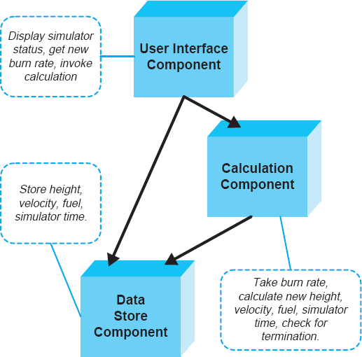
Figure 8-1. A diagram informally representing the Lunar Lander architecture using Microsoft PowerPoint.
On the other hand, a more formal architectural model of the given system may precisely define component interfaces, the conditions under which invoking a given interface is legal, a component's internal behavior, its legal external interactions, and so on. Such a model of the Lunar Lander architecture was given in Chapter 6; it is shown again in Figure 8-2. This model can be analyzed for a number of properties. For example, the model can help to ensure component composability into the system in the manner specified by the architectural configuration. After that analysis is successfully completed, the individual components may be assigned to developers for implementation. In some cases, individual component models instead may be used in further analysis to discover closely matching existing components to be grabbed off the shelf and reused in the new system. Yet another alternative would be to analyze the component model by an automated code generation tool whose output would be the component's implementation in a given programming language.
At the same time, such a rich model may not be the most effective means for answering questions about the given project's scope or about the resulting system's satisfaction of key requirements. Such questions may be more effectively answered by the system's less technical stakeholders, such as managers and customers, through informal, perhaps manual analysis of less rigorous and detailed models.
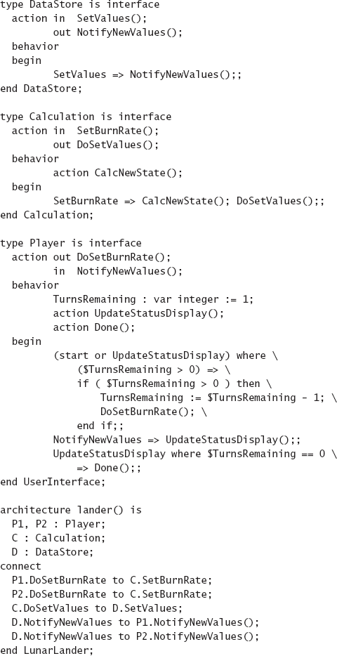
Figure 8-2. A partial, formal model of the Lunar Lander architecture corresponding to the diagram from Figure 8-1 The architecture is modeled using the Rapide ADL.
It is also crucial to recognize that analyzing a software architecture does not have the same objectives, and is not dealing with the same issues, as analyzing software programs. Architects will have to determine which problems identified in their architectures are critical, and which are not. Some problems uncovered by analysis may be acceptable if the system is still undergoing architectural design, for example, if certain parts of the architecture are still missing.
Another dimension to this issue is induced by off-the-shelf reuse of existing functionality. In naïve theory, software developers should strive to achieve perfect matches among their system's components: Each service provided by a given component will be needed by one or more components in the system, and each service required by a given component will be provided by another component in the system. In other words, there is neither any unneeded functionality provided in the system nor is there any needed functionality missing from the system. Systems developed in this manner are simpler and conceptually cleaner. However, this does not work in most large software systems, for which architecture-based development is geared. Most such systems involve the reuse of off-the-shelf functionality, and design and implementation of extensible components that will be usable in multiple systems. Therefore, certain mismatches among the components in a given architecture may be not only acceptable, but also desirable in this larger context.
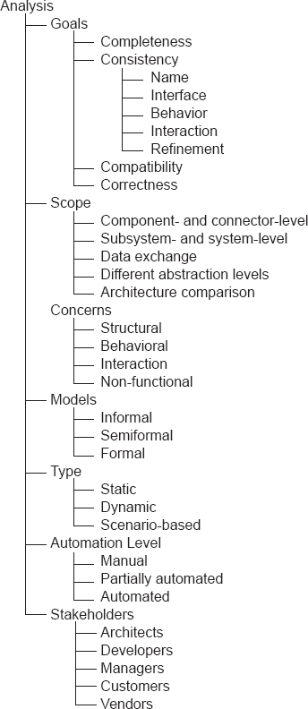
The objective of this chapter is to present and relate different facets of architectural analysis. To this end, this chapter organizes the discussion around eight dimensions of concern relevant to architectural analysis:
The goals of analysis.
The scope of analysis.
The primary architectural concern being analyzed.
The level of formality of the associated architectural models.
The type of analysis.
The level of automation.
The system stakeholders to whom the results of analysis may be relevant.
The applicable analysis techniques.
The chapter expounds upon each of the seven dimensions, and discusses how they relate to and sometimes constrain each other.
Outline of Chapter 8
8 Analysis
8.1 Analysis Goals
8.1.1 Completeness
8.1.2 Consistency
8.1.3 Compatibility
8.1.4 Correctness
8.2 Scope of Analysis
8.2.1 Component- and Connector-Level Analysis
8.2.2 Subsystem- and System-Level Analysis
8.2.3 Data Exchanged in the System or Subsystem
8.2.4 Architectures at Different Abstraction Levels
8.2.5 Comparison of Two or More Architectures
8.3 Architectural Concern Being Analyzed
8.4 Level of Formality of Architectural Models
8.5 Type of Analysis
8.6 Level of Automation
8.7 System Stakeholders
8.8 Analysis Techniques
8.8.1 Inspections and Reviews
8.8.2 Model-Based Analysis
8.8.3 Simulation-Based Analysis
8.9 End Matter
8.10 Review Questions
8.11 Exercises
8.12 Further Reading
As with analysis of any software artifact, the analysis of architectural models can have varying goals. Those goals may include early estimation of system size, complexity, and cost; adherence of the architectural model to design guidelines and constraints; satisfaction of system requirements, both functional and non-functional (see Chapter 12); assessment of the implemented system's correctness with respect to its documented architecture; evaluation of opportunities for reusing existing functionality when implementing parts of the modeled system; and so forth. We categorize such architectural analysis goals into four categories, as discussed below. We refer to these as the four C s of architectural analysis.
Completeness is both an external and an internal analysis goal. It is external with respect to system requirements. The main goal of assessing an architecture's completeness in this context is to establish whether it adequately captures all of a system's key functional and non-functional requirements. Analyzing an architectural model for external completeness is nontrivial. Software systems for which an architecture-centric development perspective is most useful are often large, complex, long lived, and dynamic. In such settings, both the captured requirements and the modeled architecture may be very large and complex, and may be captured using a multitude of notations of various levels of rigor and formality. Furthermore, both likely will be specified incrementally and will change over time, so that the system's engineers need to carefully select points at which external completeness of the architecture can and should be assessed meaningfully.
Analyzing an architecture for internal completeness establishes whether all of the system's elements have been fully captured, both with respect to the modeling notation and with respect to the system undergoing architectural design.
Establishing the completeness of the model with respect to the modeling notation (recall Chapter 6) ensures that the model includes all the information demanded by the notation's syntactic and semantic rules. For example, the architectural model depicted in Figure 8-2 is captured in the Rapide architecture description language and thus must adhere to Rapide's syntax and semantics. Given this choice of modeling notation, the component instances in the architecture portion of the model must be attached to one another (see the connect statement Figure 8-2) according to the rules of Rapide: A component's out action must be connected to another component's in action; furthermore, connectors are not declared explicitly in Rapide.
Note, however, that fulfilling the modeling requirements of a language such as Rapide does not ensure that the architecture is, in fact, captured completely. Rapide is agnostic as to whether the architect accidentally omitted a major system component or whether a specified component's interface is missing critical services. Establishing the completeness of the architectural model with respect to the system being designed requires checking—often manually, as will be further discussed later in the chapter—whether there are missing components and connectors in the architecture; whether the specified components' and connectors' interfaces and protocols of interaction are fully specified; whether all of the dependencies and interaction paths are captured by the system's architectural configuration; and so on.
In principle, internal completeness is easier to assess than external completeness, and is amenable to automation. A number of software architecture analysis techniques have focused on this very analysis category, as will be elaborated later in this chapter.
Consistency is an internal property of an architectural model, which is intended to ensure that different elements of that model do not contradict one another. The need for consistency derives from the fact that software systems, and thus their architectural models, are complex and multifaceted. As a result, even if no architectural design decisions are invalidated during the architectural design process, capturing the details of those decisions during architecture modeling may result in many inadvertently introduced inconsistencies. Examples of inconsistencies in a model include the following.
Name inconsistencies.
Interface inconsistencies.
Behavioral inconsistencies.
Interaction inconsistencies.
Refinement inconsistencies.
Name inconsistencies can occur at the level of components and connectors or at the level of their constituent elements, such as the names of the services exported by a component. The experience from using programming languages may suggest that name inconsistencies are trivial and easy to catch, but this is not always the case, especially at the architectural level. First, multiple system elements and/or services may have similar names. For example, a large system may have two or more similarly named GUI-rendering components; likewise, a large GUI component may provide two or more similarly named widget-rendering services. Determining that the wrong component or service is accessed may be difficult.
The second problem with possible name inconsistencies concerns the richness of design choices available to the software architect. In a programming language such as Java, attempting to access a nonexistent class or method will most often result in compile-time errors which the engineer must correct before moving on. This is a by-product of relatively tight coupling of different program elements: early binding, type checking, and synchronous point-to-point procedure call semantics. On the other hand, a software architect may rely on highly decoupled architectures characterized by publish-subscribe or asynchronous event broadcast component interactions. Furthermore, the architecture may be highly adaptable and dynamic, such that tracking all name mismatches at a given time may be meaningless: A component or service referred to in the architecture initially may be unavailable but will be added to the system by the time it is actually needed.
Interface inconsistencies encompass the issues present in name inconsistencies. Specifically, all name inconsistencies are also interface inconsistencies, but not the other way around. A component's required service may have the same name as another component's provided service, but their parameter lists, as well as parameter and return types, may differ.
For illustration, consider the following. The interface of a required service in a simple QueueClient component, specified using an architecture description language, may be as follows:
ReqInt: getSubQ(Natural first, Natural last, Boolean remove)
        returns FIFOQueue;
This interface is intended to access a service that returns the subset of a FIFOQueue between the specified first and last indices. The original queue may remain intact, or the specified subqueue may be extracted from it, depending on the value of the remove parameter.
On the other hand, the QueueServer component providing the service may export two getSubQ interfaces as follows:
ProvInt1: getSubQ(Index first, Index last)
          returns FIFOQueue;

ProvInt2: getSubQ(Natural first, Natural last, Boolean remove)
          returns Queue;
All three interfaces have identical names, so it can be immediately observed that there is no name inconsistency. However, the three interfaces' parameter lists and return types are not identical. Specifically:
The types of the
firstandlastparameters in the required interfaceReqIntand the provided interfaceProvInt1are different.The required interface
ReqIntintroduces a Booleanremoveparameter, which does not exist inProvInt1.Finally, the return types of the provided interface
ProvInt2and required interfaceReqIntare different.
Whether these differences result in actual interface inconsistencies will depend on several factors. If the QueueClient and QueueServer were objects implemented in a programming language such as Java, and their respective provided and required interfaces denoted method invocations, the system might not even compile. However, as has been demonstrated repeatedly throughout this book, software architecture provides a much richer set of choices to an engineer. Consider all three differences between the provided and required interfaces, and their impact on potential interface inconsistency.
If the data type
Naturalis defined to be a subtype ofIndex, then requesting thegetSubQservice will not cause a type mismatch betweenReqIntandProvInt1. Instead, a simple type cast will occur and the request will be serviced normally.If the connector between QueueClient and QueueServer components is a direct procedure call, then an interface inconsistency will occur between
ReqIntandProvInt1because of the additional parameter in the required interface. No such inconsistencies will occur betweenReqIntandProvInt2, which have identical parameter lists. On the other hand, if the two components interact via an implicit invocation mechanism, such as an event connector, the connector may simply package the request such that the QueueServer component can still service it via theProvInt1interface, by ignoring theremoveparameter: QueueServer will access only the two parameters it needs, and will not need to be concerned with any additional parameters that may have been delivered via the event. In this case, the default implementation of thegetSubQservice will simply be executed. For example, the default implementation may be that the specified subqueue is extracted from the queue. It is, of course, possible that this will not match the QueueClient's expectation ofgetSubQ's behavior, if the value ofremoveis set to false. This issue is further discussed below in the context of behavioral inconsistency.Unless this system's architectural description explicitly specifies that Queue is a subtype of FIFOQueue, or that they are identical types,
ProvInt2will not be able to service theReqIntrequest.
Determining whether there exists an interface inconsistency in a system thus depends on several factors. At the same time, this is an architecture analysis task that can be accomplished relatively easily and should be readily automatable.
Behavioral inconsistencies occur between components that request and provide services whose names and interfaces match, but whose behaviors do not. As a very simple example, consider the service exported by the following interface:
subtract(Integer x, Integer y) returns Integer;
This service takes two integers as its input and returns their difference. It is natural to assume that the subtraction is arithmetic, and many math libraries will support this as well as much more complex operations. However, the component providing this service need not calculate the two numbers' arithmetic difference, but instead may provide a calendar subtraction operation. Thus, for example, the requesting component may expect that the difference between 427 and 27 will be 400, while the component providing the service may treat it as the subtraction of 27 days from April 27, and return 331 (March 31).
An architectural model may provide a behavioral specification for the given system's components and their services. The behavioral specifications may take different forms, as illustrated in Chapter 6. For example, each required and provided interface can be accompanied with preconditions, which must hold true before the functionality exported via the interface is accessed, and postconditions, which must hold true after the functionality is exercised.
For example, let us assume that the above discussed QueueClient component requires a front operation, whose purpose is to return the first element of the queue. Furthermore, let us assume that QueueServer provides this operation, and that the two corresponding interfaces match. QueueClient's required service behavior is specified as follows:
precondition q.size ≥ 0;
postcondition ~q.size=q.size;
where ~ denotes the value of the variable q after the operation has been executed. Therefore, the QueueClient component assumes that the queue may be empty and that the front operation will not alter the queue.
Let us assume that the QueueServer component's provided front operation has the following pre- and postconditions:
precondition q.size ≥ 1;
postcondition ~q.size=q.size - 1;
The precondition asserts that the queue will be nonempty, while the postcondition specifies that the operation will alter the size of the queue (that is, that the front element will be dequeued).
A casual analysis of the two specifications indicates that the behavior of the front operation required by QueueClient does not match that provided by QueueServer. The postconditions clearly are different; moreover, the provided operation assumes that front will not be invoked before the existence of at least one element in the queue is ascertained.
A component's behavior may be specified in several different ways. Chapter 6 discussed several examples, including state-transition diagrams, communicating sequential processes, and partially ordered events sets. The exact manner in which the behavioral consistency between services is ensured will vary across these notations, and hence is outside the scope of this text. On the other hand, the overall analysis process will follow the general pattern outlined above, regardless of the behavior modeling notation.
Interaction inconsistencies can occur even if two components' respective provided and required operations have consistent names, interfaces, and behaviors. An interaction inconsistency occurs when a component's provided operations are accessed in a manner that violates certain interaction constraints, such as the order in which the component's operations are to be accessed. Such constraints comprise the component's interaction protocol.

Figure 8-3. Interaction protocol for the QueueServer component. Transitions corresponding to operations such as front and is_empty, typically provided by a queue component, have been elided for clarity. Transition guards are enclosed within brackets. The assumption is that the queue can contain at least two elements.
A component's interaction protocol can be specified using different notations. Frequently, it is modeled via state-transition diagrams (Yellin and Strom 1994). Analyzing the system for interaction consistency in that case consists of ensuring that a given sequence of operation requests matches some sequence of legal state transitions specified by each component's protocol.
An example of such interaction protocol is provided in Figure 8-3. In the figure, the QueueServer component requires that at least one element always be enqueued before an attempt to dequeue an element can be made; furthermore, it assumes that no attempts to enqueue elements onto a full queue will be made. A QueueClient component that does not adhere to these constraints—that is, whose sequence of invocations cannot be executed by the state machine from Figure 8-3—will cause an interaction inconsistency with the QueueServer.
Refinement inconsistencies stem from the fact that a system's architecture is frequently captured at multiple levels of abstraction. For example, a very high-level model of the architecture may only represent the major subsystems and their dependencies, while a lower-level model may elaborate on many details of those subsystems and dependencies. As an illustrative example, Figure 8-4 shows the high-level architecture of the Linux operating system, provided by Ivan Bowman and colleagues. (Bowman, Holt, and Brewster 1999), and its Process Scheduler subsystem modeled as a composite connector, provided by Mehta et al. (Mehta, Medvidović, and Phadke 2000). Analyzing Linux's architecture for consistency would require establishing the following three conditions:
The elements of the higher-level architectural model have been carried over to the lower-level model—that is, no existing architectural elements have been lost in the course of the refinement.
The key properties of the higher-level model have been preserved in the lower-level model—that is, no existing architectural design decisions have been omitted, inadvertently changed, or violated in the course of the refinement.
The newly introduced details in the lower-level model are consistent with the existing details of the lower-level model —that is, none of the new design decisions inadvertently change or violate the existing design decisions.
![A very high-level model of the Linux operating system [adopted from Bowman et al. (Bowman, Holt, and Brewster 1999) © 1999 ACM, Inc. Reprinted by permission.] and a detailed model of the Linux Process Scheduler connector.](http://imgdetail.ebookreading.net/software_development/33/9780470167748/9780470167748__software-architecture-foundations__9780470167748__figs__0804.png)
The reader should observe that Figure 8-4 does not contain enough information to establish the above three conditions. This is because both the higher-level and the lower-level models are incomplete. The one observation that can be made with certainty is that the Linux Process Scheduler has been maintained as a separate entity between the two refinement levels. However, at the lower level it is modeled as a connector, while at the higher level it was a component. Further analysis, and additional information on which to base that analysis, would be required before any specific determination can be made as to whether this decision—to change a component into a connector—violated any higher-level architectural design decisions and what impact it had on the rest of the architecture.
Compatibility is an external property of an architectural model, intended to ensure that the model adheres to the design guidelines and constraints imposed by an architectural style, a reference architecture, or an architectural standard. If the design constraints are captured formally, or at least rigorously, ensuring an architecture's compatibility to them will be relatively straightforward. If an architecture must be compatible with a set of semiformally or informally specified design guidelines, analyzing the architecture for compatibility may be more challenging and the outcome of the analysis process also may be ambiguous at times.
Reference architectures are usually specified formally, using an architecture description language. Therefore, establishing the compatibility of a given system's architecture to the reference architecture may be a precise and automatable process. Since a reference architecture captures a set of properties that must hold true across any number of systems in a given domain, it may be only partially specified or certain parts of it may be at a very high level of abstraction. In such cases, establishing that a product-specific architecture adheres to the reference architecture can be accomplished by ensuring refinement consistency, in the manner discussed above.
However, as the reader will recall from Chapter 4 and will see in later chapters, most architectural styles and many standards provide general, high-level design guidelines, so that establishing an architecture's adherence to them may be more challenging. The difficulty may arise from fuzziness on the part of the style definition or imprecision or incompleteness on the part of the architectural model. For example, Figure 8-5 depicts the Lunar Lander architecture according to the event-based style. This diagram was first shown in Chapter 4, with a slightly different component layout, as were the relatively similar diagrams for the Lunar Lander architectures in the C2 (Figure 4-23) and blackboard (Figure 4-16) styles. Determining the style to which this architecture adheres is a nontrivial task: The depicted configuration of components may, in fact, also adhere to C2's principles, such as substrate independence. Likewise, this particular visual layout of the architecture's topology may be misleading, for the Spacecraft component may in fact play the role of a blackboard in this system. In cases such as this, the architect may need to obtain additional information, rely on tacit knowledge, and use one or more architectural analysis techniques presented later in this chapter.

Correctness is an external property of an architectural model. A system's architecture is said to be correct with respect to an external system specification if the architectural design decisions fully realize those specifications. Furthermore, the system's implementation is correct with respect to the system's architecture if the implementation fully captures and realizes all the principal design decisions comprising the architecture. Correctness is therefore relative : It is the result of architecture to some other artifact, where the artifact is either intended to elaborate and fulfill the architecture or the architecture is intended to elaborate and fulfill the artifact.
An interesting observation arises in the implementation of many large, modern software systems that reuse off-the-shelf functionality, or off-the-shelf architectural solutions such as reference architectures. In such cases, it is very likely that, through the off-the-shelf components, the implemented system will include structural elements or functionality, as well as non-functional properties, that are not specified in the requirements and/or not modeled in the architecture. With a 1970's notion of refinement-based correctness, such systems would not be considered to be correct with respect to the architecture. However, with the notion of correctness built upon fulfillment, as described above, such systems are not only correct, but they are likely efficiently created and form a suitable basis for efficiently fulfilling new system requirements.
A software system's architecture can be analyzed from different perspectives and at different levels. Architects may be interested in assessing the properties of individual components or connectors, or even their constituent elements, such as interfaces or ports. More frequently, architects may be interested in the properties exhibited by compositions of components and connectors in a given subsystem or entire system. A specific focus of (sub)system-level analysis may be on the data exchanged among the system elements.
In addition to assessing the properties of a single architecture, architects may at times need to consider two or more architectures simultaneously. One such case is when a given system's architecture is analyzed at multiple levels of abstraction. For example, a more detailed architectural model may be compared to the higher-level model from which it has been derived, to ensure that no existing design decisions have been violated or unintended design decisions introduced. A similar type of analysis takes place when two architectural models at similar levels of abstraction are compared to establish design similarities or conformance to constraints such as those embodied in a reference architecture.
In a large system, individual components and connectors may not always be as interesting to an architect as their compositions, but both components and connectors need to provide specific services at specific quality levels. In the case of components, this typically means application-specific functionality; in the case of connectors, this means application-independent interaction services.
The simplest type of component- and connector-level analysis ensures that the given component or connector provides the services expected of it. For example, a component's or connector's interface can be inspected to make sure that no expected services are missing. As an illustration, Figure 8-6 shows Lunar Lander's Data Store component modeled in xADLite. It is trivial to analyze this component, either manually or automatically, to establish that it provides both getValues and storeValues services; furthermore, if a system stakeholder expects or requires the Data Store component to provide further services, it can easily be ascertained that no such services currently exist. Even if the component were much larger and provided many more services, this task would not be significantly harder.
Of course, "checking off" the services a component or connector provides does not ensure that those services are modeled correctly. The described analysis can be thought of as equivalent to establishing only name consistency. A component or connector may provide services with the expected names, but with incorrect interfaces. For example, getValues in the above example may be modeled to expect the values in a wrong format, such as untyped versus typed or string versus integer. Therefore, it is not sufficient to establish that the component or connector provides appropriately named services; the complete interface of the component or connector has to be analyzed. The information provided in Figure 8-6 will thus have to be supplemented with additional details, possibly from other models.
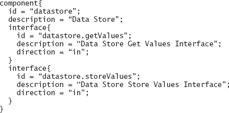
Figure 8-6. Lunar Lander's Data Store component modeled in xADLite. This model is extracted from that provided in Chapter 6, in Figure 6-27.

Taking this argument a step further, it is not sufficient to ensure that the component's or connector's services are exported via an appropriate interface. The semantics of those services as modeled (and, eventually, as implemented) may be different from the desired semantics. Thus, for example, the getValues service from Figure 8-6 may not be modeled such that it accesses the Data Store to obtain the needed values, but instead may request those values from a system user. Since the intended usage of the component, implied in its name, is to access a repository, this implementation of getValues, while legitimate in principle, would be wrong for this context.
Similarly, a connector may provide interaction services with semantics that are different from the expected semantics. For example, a connector may be expected to support asynchronous invocation semantics, but is actually modeled for synchronous invocation. Establishing this type of semantic consistency is not trivial. Consider as an illustration a model of a Pipe connector in the Wright ADL discussed in Chapter 6; the model is depicted in Figure 8-7. The Pipe connector plays two roles; that is, it provides two services: Reader and Writer. Their interplay, that is, the connector's overall behavior, is captured by the connector's glue. Even though a pipe is a relatively simple connector, establishing manually that it adheres to its expected behavior is significantly more challenging than with name or interface conformance. For example, is the intended semantics to allow unimpeded writing to the pipe, as in the current specification of the Writer role, or does the pipe have a bounded buffer so that writing a certain amount of data would require that at least some of that data be read before additional data can be written? Assessing more complex connectors for these types interaction properties will be much more difficult and may be especially error-prone.
Even if individual components and connectors have desired properties, no guarantees can be made that their compositions in a given system will behave as expected, or even be legal. The interplay among complex components can itself be very complex. Architects may assess the properties of their compositions at the level of the entire system or incrementally, by focusing on particular subsystems.
The most manageable increment is pair-wise conformance, where only two interacting components are considered at a time, and name, interface, behavior, and interaction conformance are established as discussed above. The next step up is to take a set of components possibly interacting through a single connector, such as those shown in Figure 8-5. Most analysis techniques can easily support both these cases. Ensuring desirable properties at the level of large subsystems and entire systems can be quite challenging, and many analysis techniques have tried to get a handle on this problem.
In certain scenarios it may be obvious that compositions of two or more components that respectively possess properties α, β, γ, and so forth will have some combination of those properties. For example, combining a data encryption component—intended to provide communication security—with a data compression component—intended to provide communication efficiency—can be expected to provide both security and efficiency.
Much more frequent in practice is the situation where the interplay among the components will result in their interference and either enhancement or diminishment of each other's properties. This will be acceptable, and even desirable, in certain cases. For example, a component that provides a critical service very efficiently may be vulnerable to malicious attacks. The system architects may decide that sacrificing some of the efficiency is acceptable in order to enhance the system's security, and may compose this component with one or more components that provide services such as encryption, authentication, or authorization. Likewise, in many real-time systems, a component that computes its results or provides data more quickly and/or frequently than the system requires will be composed with a (simple) component that introduces the necessary delays. Such compositions will be synergistic: The system will ultimately be greater than the sum of its parts.
Such interference among system components will not be desirable in all situations. More importantly, such interference will often not be as obvious as in the above scenarios and will result in unintended composite properties. Examples abound. One such well-known example from software engineering literature involved integrating two components that both assumed that they owned the system's main thread of control, ultimately resulting in an unusable system (Garlan, Allen, and Ockerbloom 1995). Another similar example involved integrating concurrent components implemented in two different programming languages. The resulting system's performance was unacceptable, and a long and painstaking analysis of the system uncovered that the individual components' threading models were incompatible (Maybee, Heimbinger, and Osterweil 1996). The reader can easily envision many other such scenarios, such as when a system comprises interacting memory-efficient components (which use computationally intensive data compression algorithms) and CPU-efficient components (which use techniques such as data caching and prefetching) or, further, when a component introducing a fault-tolerance service (for example, via continuous state replication) is introduced into such a system.
In many large, distributed software systems large amounts of data are processed, exchanged, and stored. Examples of data-intensive systems are numerous and appear in such wide ranging domains as scientific computing, many Web-based applications, e-commerce, and multimedia. In such systems, in addition to the properties of the individual structural architectural elements—components and connectors—and the entire architectural configuration, it is important to ensure that the system's data is properly modeled, implemented, and exchanged among the structural elements. This involves assessing the data elements, including the following.
The structure of the data, such as typed versus untyped or discrete versus streamed.
The flow of the data through the system, such as point-to-point versus broadcast.
The properties of data exchange, such as consistency, security, and latency.
As a simple example, consider a system consisting of a data-producer component and two data-consumer components, whose architectural configuration is depicted in Figure 8-8. The figure also shows the respective frequencies at which they are able to exchange data. The Producer component sends one megabit per second, and Consumer 1 is able to receive and process that data in a timely manner. In fact, Consumer 1 may wait idly up to 50 percent of the time to receive additional data from the Producer. However, Consumer 2 is able to receive and process the data at a rate that is only one-half of the production rate. This means that Consumer 2 may lose up to one-half of the produced data.
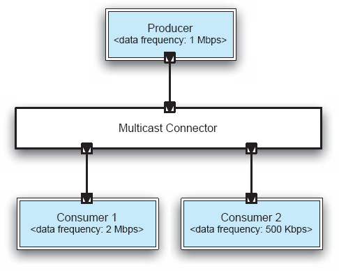
Figure 8-8. A simple system with one data producer and two consumers, with the frequencies at which they are able to send and receive data, respectively.
This problem may be mitigated if the Multicast Connector servicing the three components is able to buffer data, but clearly, if the system is long running, the connector's buffer will eventually overflow. The connector will also have to include additional processing logic to store the data temporarily and also route it to the two components in the order received, which will introduce additional overhead in the system. If the two Consumer components require the data to be in different formats from that generated by the Producer, the connector will also have to act as an adapter, introducing further overhead. Likewise, the connector may have to perform additional tasks based on the architectural requirements, such as encrypting the data for security, ensuring that the data is delivered according to the specified routing policy (for example, best-effort or exactly-once), or compressing the data if necessary.
During the architectural design process, architects frequently address the critical system requirements first, and then both introduce additional elements into the architecture and refine the architecture to include additional details that are necessary for the architecture's realization into the final system. This may involve the addition and further breakdown of architectural elements, as well as the introduction and refinement of existing design decisions.
Consider a simple example. A high-level architectural breakdown of a system may look like the diagram shown in Figure 8-9. For simplicity, the connectors are depicted only as arrows indicating the interacting components as well as the direction of interaction. For example, component C1 initiates the interactions with components C3 and C4. As is the case with all boxes-and-arrows architectural descriptions, many details of this architecture are missing, including the components' interfaces, details of their behaviors and of the data exchanged, as well as the semantics of their interactions, such as that involving components C1, C2, and C3. While important, such information is not critical to this discussion.


Figure 8-10 depicts another architectural configuration, which is intended to be a refinement of that shown in Figure 8-9. For convenience, groups of components in the refined architecture which are presumed to comprise the original components are highlighted. For example, components C11, C12, C13, and C14 along with their interconnections in Figure 8-10 comprise the component C1 from Figure 8-9. Furthermore, the connectors are refined, such that it is clear that only C1's subcomponent C14 is engaged in interactions with the subcomponents of C3 and C4.
In the process of refinement, several problems can be introduced, as discussed above in the context of refinement incompatibility. The easiest cases to address are those where an architectural design decision has been clearly invalidated. However, even the addition or modification of architectural decisions may cause a refinement inconsistency depending on the context and on the range of architectural changes that are allowed. For example, the architecture depicted in Figure 8-9 and Figure 8-10 may need to abide by an architectural constraint stating that interactions crossing the boundaries of the system's original four components must have a single target and a single destination. In that case, elaborating the interactions among the architecture's components as shown in Figure 8-10 would violate the constraints, both in the case of component C1's interactions with C3 and C4's interactions with C2.
Clearly, based on the scant information provided about the architectures in Figure 8-9, it is unclear whether the changes to the original architecture depicted in Figure 8-10 should be allowed. This will depend on many factors, and some, though not all, will be apparent from a more detailed and rigorous modeling of the architecture such as discussed in Chapter 6. This will also depend on a refinement policy, which may be explicitly stated. Thus, for example, Mark Moriconi and colleagues define a refinement policy called conservative extension (Moriconi, Qian, and Riemenschneider 1995). Conservative extension essentially precludes an architect from introducing any new features into a system's architecture, and instead restricts him or her to either elaborating or possibly eliminating those features already existing in the more abstract, that is, higher-level, architecture. While a property such as conservative extension may not always be useful in practice, Moriconi and colleagues have shown it to be amenable to formal specification and analysis. Other refinement policies may be much less restrictive, but that very flexibility may make it difficult to establish that they are being adhered to in a concrete situation.
In certain situations it is important for architects to understand the relationship between the architecture they are interested in and a baseline architecture with known properties. One such case, discussed previously in this chapter, is ensuring the compliance of a given system's architecture with a reference architecture. Other cases may include ensuring the architecture's compliance with the design guidelines captured in an architectural style or with a particular architectural pattern. It is, of course, also possible that the baseline architecture is simply one that the architect knows and understands. The architect may have encountered the architecture in literature, it may be the architecture of a related product he or she and colleagues had developed previously, or it could even be an architecture that has been recovered from a system (possibly even competitor's system) that exhibits desired properties.
Such comparisons of two or more architectures involve comparing the processing and data storage capabilities provided by the components, the interactions as embodied in the connectors, the characteristics of the data exchange, the components' and connectors' compositions into the system's configuration, and the sources of the non-functional properties exhibited by the system. It is possible for the architectures in question to be at different levels of abstraction, in which case the techniques discussed in the previous subsection can be employed.
Architectural analysis techniques are directed at different facets of a given architecture. Some techniques strive to ensure primarily the architecture's structural properties; others focus on the behaviors provided by the architectural elements and their composition; yet others may analyze whether the interactions among the architectural elements adhere to certain requirements and constraints; finally, the non-functional properties exhibited by the architecture are frequently considered to be very important and are thus studied carefully.
In practice, a given analysis technique, or suite of techniques, will address more than one architectural concern at a time. In this section, we focus on each concern individually for ease of exposition and also discuss the relevant characteristics of each.
The structural characteristics of a software architecture include concerns such as the connectivity among an architecture's components and connectors, containment of lower-level architectural elements into composite higher-level elements, possible points of network distribution, and a given system's potential deployment architectures. These concerns can help to determine whether the architecture is well formed. Examples include components or subsystems that are disconnected from the rest of the architecture, missing pathways between components and connectors that are intended to interact, existing pathways between components and connectors that are not wanted, encapsulation of components or connectors that must be visible and accessible at a higher level of hierarchical composition, and so on. Structural analysis can also establish adherence to architectural constraints, patterns, and styles. Structural concerns can also help in the analysis of different aspects of system concurrency and distribution, as they tie the system's software elements and their properties with the hardware platforms on which they will execute.
A well-structured architecture is of limited utility if the individual components do not provide the behaviors that are expected of them and, further, if they do not combine to provide the expected system-level behaviors. Therefore, analyzing an architecture's behavioral characteristics has two related facets:
Considering the internal behaviors of individual components.
Considering the architectural structure to assess composite behaviors.
It is possible, especially in systems composed with third-party components obtained off the shelf, that an architect's insight into the internal workings of different system components will be restricted to the components' public interfaces. As indicated earlier, particularly in Section 8.1, the types of behavioral properties that can be inferred at the level of interfaces are quite limited, and many potential problems with the architecture may remain undetected.
The relevant characteristics of interactions in a given architecture may include the numbers and types of distinct software connectors, and their values for different connector dimensions (recall Chapter 5). Interaction characteristics can help to establish whether the architecture will actually be able to fulfill some of its requirements. For instance, a non-buffering connector in the example from Figure 8-8 would result in a system in which one of the components received at most one-half of all the data.
Analysis of interaction characteristics may also encompass the interaction protocols for different system components (for example, recall Figure 8-3) and internal behaviors specified for different system connectors (for example, recall Figure 8-7). Such details would aid in the analysis of finer-grain interaction characteristics, such as whether a component interacting through an otherwise appropriate connector will be legally accessed or whether a set of interacting components may deadlock.
Non-functional characteristics form a critical dimension of almost all software systems. These characteristics typically cut across multiple components and connectors, which makes them particularly difficult to assess. Furthermore, non-functional characteristics are often not properly understood, they are qualitative in nature, and their definitions are partial or informal. Therefore, while the non-functional characteristics present an important and formidable challenge to software architects, architectural analysis techniques focusing on these characteristics are scarce.
The relationship between architectural models and analysis is symbiotic: What the system's stakeholders want to be able to analyze will influence what software architects capture in their architectural models. Conversely, what architects capture in the architectural models directly determines what they will be able to analyze and what analysis methods they will use to do so.
Architectural models have been discussed in detail in the preceding chapters, and particularly in Chapter 6. Here, we will look specifically at the role they play in the context of architectural analysis. For that purpose, architectural models can be classified as informal, semiformal, and formal.
Informal models are typically captured in boxes-and-lines diagrams such as shown in Figure 8-1. Informal models can provide a useful high-level picture of the system. They are amenable to informal and manual analyses, typically by a broad section of stakeholders, including nontechnical stakeholders such as managers and system customers. For example, system managers can use them to determine a project's overall staffing needs. At the same time, informal models should be approached cautiously because of their inherent ambiguity and lack of detail.
Most architectural models used in practice are semiformal. A notation that strives to be useful to a large number of system stakeholders, both technical and nontechnical, will typically try to strike a balance between a high degree of precision and formality on the one hand, and expressiveness and understandability on the other. One widely used example is the Unified Modeling Language (UML). Semiformal languages such as the UML are amenable both to manual and automated analysis. Their partial imprecision makes it difficult to perform some more sophisticated analyses, for which formal models are needed.
While semiformal modeling notations typically only have a formally defined syntax, formal notations also have formally defined semantics. An example formal notation is Wright, which was used to specify the Pipe connector in Figure 8-7. Formal models are inherently amenable to formal, automated analysis and are typically intended for the system's technical stakeholders. At the same time, producing complete architectural models using a formal notation can be painstaking. Furthermore, formal models have been frequently shown in practice to suffer from scalability problems.
One useful categorization of architectural analysis techniques is into static, dynamic, or scenario-based techniques. We discuss the three categories and the role architectural models play in each.
Static analysis involves inferring the properties of a software system from one or more of its models, without actually executing those models. A simple example of static analysis is syntactic analysis: Determining if the system model adheres to the syntactic rules of the modeling notation, whether it be an architectural description language, design diagramming notation, or programming language. Static analysis can be automated (for example, compilation) or manual (for example, inspection). All architectural modeling notations, including the informal boxes-and-lines diagrams, are amenable to static analysis, although the more formal and expressive notations can be harnessed to provide more precise and sophisticated answers. Formal notations used in modeling software systems include:
Axiomatic notations, which model systems via logical assertions; an example is Anna (Luckham and Henke 1985).
Algebraic notations, which model systems via collections of equivalence relations; an example is LARCH (Guttag, Horning, and Wing 1985).
Temporal logic notations, which model systems in terms of order of execution and timing; an example is GIL (Dillon et al. 1992).
It should be noted that the above example notations cannot be considered as architecture description languages, or ADLs, since by themselves they do not provide any explicit architecture modeling constructs. However, it is possible to use them as a basis of an ADL, much in the same way that Wright leverages communicating sequential processes (CSP) as discussed in Chapter 6.
Dynamic analysis involves actually executing or simulating the execution of a model of the software system. In order to perform dynamic analysis on an architectural model, its semantic underpinning must be executable or amenable to simulation. State-transition diagrams are an example executable formalism with which the reader should be familiar. Other executable formalisms include discrete events, queuing networks (Lazowska et al. 1984), and Petri nets.
For large and complex software systems, it is often infeasible to assert a given property for the entire system over the entire space of its possible states or executions. For such systems, specific-use cases are identified that represent the most important or most frequently occurring system usage scenarios, and the analysis is focused on those. Scenario-based analysis can be an instance of both static analysis—as a tool for reducing a modeled system's state space, as discussed later in this chapter—and dynamic analysis—as a tool for reducing the system's execution space. At the same time, scenario-based analysis requires that architects be very careful about the inferences they make from their inherently limited evidence.
Different architectural analysis techniques are amenable to different levels of automation. The level of automation depends on several factors, including the formality and completeness of the architectural model and the property being assessed. In general, an architectural model provided in a more formal notation will be more amenable to automated analysis than a model provided in a more informal notation. Likewise, a model that captures a greater number of the architectural design decisions for the given system will be more amenable to rigorous, automated analysis than a model that is missing many such design decisions. Finally, a well-understood property that is quantifiable and can itself be defined formally will be easier to assess automatically than a qualitative property that may not be as well understood. This last point is particularly important in software engineering: As will be demonstrated in Chapter 12, many non-functional properties, which are critical to the success of most all software systems, are understood at the level of intuition, anecdote, and informal guideline.
Manual analysis of software architectures requires significant human involvement, and is thus expensive. However, manual analysis can be performed on models of varying levels of detail, rigor, formality, and completeness. It has the added advantage that architectural rationale, which is often tacit, can be taken into account. This type of analysis may also be required when multiple, potentially clashing properties must be ensured in tandem.
A number of architectural analysis techniques fall in this category. These are inspection-based techniques and will be further elaborated upon later in this chapter. One well-known example is the architecture trade-off analysis method, or ATAM (Clements, Kazman, and Klein 2002). The analysis results emerging from manual analysis are typically qualitative. Since it is not always possible to quantify important properties of a software system—such as scalability, adaptability, or heterogeneity—any analysis of the extent to which the system exhibits those properties will not be quantifiable. The analysis results are also frequently qualified by a particular context in which a system may exhibit a given property. Scenario-based techniques fall in this category.
Given the human-intensive nature of this category of architecture analysis techniques, a critical concern must be to make the analysis reliable and repeatable. Since the architectural models as well as the properties of interest may be less than formally captured, the focus of many manual analysis techniques has been on specifying a detailed process that must be followed by the system architects and other stakeholders participating in the analysis.
Growing levels of rigor in architectural models, and in understanding of the software systems' key properties, present opportunities for automating different facets of architectural analysis. In fact, most architectural analyses can be at least partially automated, involving both software tools and human intervention. In that sense, architectural analysis techniques can be thought of as covering a spectrum of automation, with manual and fully automated analysis being the ends of that spectrum.
Most architecture modeling notations presented in Chapter 6 are amenable to ensuring a given architectural description's syntactic correctness, as well as different degrees of semantic correctness. For example, an xADL model can be analyzed for style-specific component interconnectivity rules, while Wright allows one to analyze a given composition of components communicating through a connector for deadlocks. At the same time, neither model can be analyzed automatically for other properties, such as reliability, availability, dependability, or latency. This is at least in part because system parameters that are relevant to assessing these properties are not captured—to the necessary degree, or at all—by these architectural modeling notations.
It can be argued that the specific analyses mentioned above, such as ensuring the syntactic correctness or deadlock freedom in an architectural description, can be considered fully automatable since it is possible to complete them without human involvement. At the same time, the results of automated analyses are typically partial: The fact that an architectural description provided in a given ADL fully adheres to that ADL's syntax, or that a partial system description is deadlock free, still leaves a large number of questions about the respective models unanswered. This means that, in practice, fully automated architectural analysis techniques must be combined with other techniques, which themselves may need human intervention, in order to get more comprehensive answers.
The stakeholders in a software project will often have different objectives. For example, customers may be interested in getting the most functionality as quickly as possible, for the lowest amount of money possible. A project manager may be interested in ensuring that the project is staffed appropriately and that the rate of expenditure does not exceed some target. The architects' primary objective may be to deliver a technically sound system that will be easily adaptable in the future. Finally, a developer may be interested primarily in ensuring that the modules he or she is responsible for are implemented on time and bug-free. Therefore, the different stakeholders will not necessarily have identical architecture analysis needs. The remainder of this section highlights the role architectural analysis plays in the case of each stakeholder type.
Software architects must take a global view of the architecture and are interested in establishing all four C s in the architecture: completeness, consistency, compatibility, and correctness. Depending on the project's context and objectives, architects may need to rely on all types of architectural models at all levels of scope and formality. While they may prefer to use automated analysis techniques, architects will frequently have to rely on manual and semi-automated techniques.
Software developers often take a more limited view of the architecture—namely, the modules or subsystems for which they are directly responsible. As such, developers are interested primarily in establishing the consistency of their modules with other parts of the system with which these modules will interact, as well as compatibility with the required architectural styles, reference architectures, and standards. They need not worry about the architecture's completeness, and can at best assess its partial correctness. The models that developers will likely find most useful are formal, with all necessary details specified and ready for implementation. However, these likely would be models of individual elements for which a given developer is directly responsible, rather than models of the entire architecture.
Project managers are typically primarily interested in an architecture's completeness—Are all the requirements satisfied?—and correctness—Are the requirements appropriately realized in the architecture and thus eventually will be realized in the implementation? Managers may also be interested in the architecture's compatibility if the architecture and eventually the implemented system must adhere to a reference architecture or a set of standards.
Consistency is a system's internal property, and managers typically do not concern themselves with it, that is, they naturally delegate such responsibilities to architects and developers. There are exceptions, however. For example, architectural defects may become a major issue that begins affecting the project's schedule or budget. Alternatively, customers or project contracts may explicitly mandate certain consistency properties, in which case managers would need to explicitly consider them.
The types of architectural models that are useful to managers are usually less formal models of the entire system. A manager's focus will frequently be on cross-cutting non-functional system properties, as well as the system's structural and dynamic characteristics.
Customers are interested primarily in the commissioned system's completeness and correctness. Their concerns can be summarized with two key questions:
Is the development organization building the right system?
Is the development organization building the system right?
A customer may also be interested in the system's compatibility with certain standards, and possibly reference architectures in which the customer has a vested interest. Consistency is not of critical importance unless it is reflected in externally visible system defects.
In terms of architectural models, customers typically favor understandability over formality of models. They are interested in overall models (the "big picture"') and the system's key properties. They are often interested in scenario-driven assessment of a system's structural, behavioral, and dynamic characteristics.
Software vendors typically sell technology, such as individual components and connectors, rather than architecture. As such they are interested primarily in composability of those components and connectors as well as their compatibility with certain standards and widely used reference architectures. Like a given system's customers, vendors may value the understandability of architectural models, but their customers are software developers who may demand formal models of the software they purchase from the vendor. The vendors' primary focus is on the analysis of the individual elements and their properties. The structural characteristics of the overall architecture are not as important, although dynamic characteristics may be since they may have implications on the composability of the individual elements in future systems.
A large number of analysis techniques are available to software architects. Some of them are variations on techniques applied to other software development artifacts—primarily formal specifications and code—while others have been developed specifically with software architectures in mind. In this section we discuss a cross-section of architectural analysis techniques. Although it is not intended to provide a complete overview of existing techniques, the cross-section is broadly representative.
We divide architectural analysis techniques into three categories:
Inspection- and review-based.
Model-based.
Simulation-based.
The discussion of the techniques within these categories will focus on the architectural analysis dimensions outlined above and summarized in Figure 8-11.
Software inspections and reviews are widely used code-analysis techniques. If unfamiliar with these techniques, the reader is encouraged to consult an introductory software engineering text. Architectural inspections and reviews are conducted by different stakeholders to ensure a variety of properties in an architecture. They involve a set of activities conducted by system stakeholders in which different architectural models are studied for specific properties. These activities often take place in architecture review boards, where several stakeholders define the objective of the analysis—such as ensuring that the architecture satisfies a given non-functional property—and then, as a group, carefully study and critique the architecture or some of its parts.
Inspections and reviews are manual analysis techniques, and as such can be expensive. On the other hand, they have the advantage of being useful in the case of informal or partial architectural descriptions. They can also be employed effectively in the case of "soft"' architectural properties, such as scalability or adaptability, which are not precisely understood and amenable to formal definition. Another advantage of inspections and reviews is that they can simultaneously take into account the objectives of multiple system stakeholders and consider multiple desired architectural properties.
Depending on the context, inspections and reviews can have any of the four architectural analysis goals : consistency, correctness, completeness, and compatibility. In terms of consistency, they will typically be well suited to name and interface consistency analysis. Behavior, interaction, and refinement consistency analysis may be conducted by the technical stakeholders—architects and developers—although doing so manually may be a difficult and error-prone task. For example, recall the interaction characteristics embodied in the single Wright Pipe connector from Figure 8-7, and even the comparatively simpler single state-transition interaction protocol of the QueueServer component from Figure 8-3. Dealing with a large number of such models manually would cognitively overload even the most capable architects. Thus, if analyzing for any of the three latter types of consistency is undertaken during an architectural inspection or review, it may be advisable to restrict the analysis to carefully confined subsets of the architecture.
The scope of inspections and reviews can vary. The stakeholders may be interested in individual components and connectors, or their compositions in a specific subsystem or the entire system. The stakeholders may also center on the data exchanged among the specific components and connectors or, globally, across the entire architecture. They may try to assess the compliance of the architecture to a higher-level architecture that served as its starting point. They may also try to assess the architecture's similarity to an existing architecture with known properties.
Similarly, the specific concern of the analysis can vary. The stakeholders may focus on the structural, behavioral, or interaction properties, although as mentioned above, the latter two may be difficult to assess manually. Inspections and reviews may be particularly well suited to establishing certain non-functional properties, especially those that require some interpretation and consensus reaching by the human stakeholders.
In terms of the types of models particularly amenable to inspections and reviews, any level of formality may be suitable in principle. However, highly formal models will not be useful to the nontechnical stakeholders, and even the technical stakeholders may find them difficult to read and understand. At the other end of the spectrum, informal models may be useful if, for example, the objective of the inspection is to develop a common understanding of the architecture's general characteristics. On the other hand, it may not be very meaningful to rely on informal models when inspecting the architecture for concrete properties of interest.
By their nature, the types of analysis for which inspections and reviews are geared are static and scenario-based. Since the stakeholders manually assess the architectural models, they have to focus on the architecture's static properties, such as proper connectivity, interface conformance between interacting components, adherence to desired architectural patterns, and so on. Furthermore, as discussed below in the case of the ATAM analysis technique, the stakeholders may manually run through some critical scenarios to ensure that the architecture will behave as expected.
As already mentioned, in terms of automation level inspections and reviews are manual and very human intensive.
Finally, all system stakeholders, save for perhaps component vendors, may participate in inspections and reviews. Architects and developers will conduct inspections and reviews most frequently, and will periodically be joined by project managers and possibly by customers.
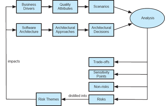
Figure 8-12. The high-level view of the process steps followed in ATAM. The diagram has been adopted from Carnegie Melon University's Software Engineering Institute.
The Architectural Trade-Off Analysis Method (Clements, Kazman, and Klein 2002), or ATAM, developed at Carnegie Melon's Software Engineering Institute, is a human-centric process for identifying risks in a software design early in the development life cycle. ATAM specifically focuses on the quality attributes, or non-functional properties (NFPs), of modifiability, security, performance, and reliability. Its objective is to reveal not only how well an architecture satisfies given quality goals, but also how those goals trade off against each other.
The ATAM process requires the gathering of the software architects designing the system, other important stakeholders of that system, and a separate independent architecture evaluation team. An evaluation using ATAM typically takes three to four days. The set of activities followed are depicted in Figure 8-12.
Two key inputs into the ATAM process are the business drivers and the system's software architecture. A project's decision maker, who is usually the project's manager or customer, first presents the system's major business drivers. These include:
The system's critical functionality.
Any technical, managerial, economic, or political constraints.
The project's business goals and context.
The major stakeholders.
The principal quality attribute (NFP) goals that impact and shape the architecture.
The quality attributes become a basis of eliciting a set of representative scenarios that will help ensure the system's satisfaction of those attributes. There are three scenario categories in ATAM.
Use-case scenarios, which describe how the system is envisioned by the stakeholders to be used.
Growth scenarios, which describe planned and envisioned modifications to the architecture.
Exploratory scenarios, which try to establish the limits of architecture's adaptability by postulating major changes to the system's functionality, operational profiles, and underlying execution platforms.
Once the scenarios are identified, they are prioritized in terms of importance by the system's stakeholders.
Another thread of activity in ATAM involves the project's architects presenting the key facets of the architecture. This includes:
Technical constraints, such as the required hardware platforms, operating systems, middleware, programming languages, and off-the-shelf functionality.
Any other systems with which the system under development must interact.
Architectural approaches that have been used to meet the quality requirements.
An architectural approach in ATAM refers to any set of architectural design decisions made to solve the problem at hand. Architectural approaches are typically architectural patterns and styles. The architectural approaches are used to elaborate the architectural design decisions made for the system.
The key step in ATAM is the analysis of the architectural approaches in the context of the identified scenarios, with the primary goal of establishing the relationship between the approaches—that is, architectural design decisions—and quality attributes. The analysis is not rigorous, but rather is intended to observe general, coarse-grained characteristics of the architecture. To this end, for each architectural approach a set of analysis questions are formulated that are specific to the quality attributes and architectural approach under consideration. The system's architects engage with the ATAM evaluation team in answering these questions. The answers particularly focus on the architectural approach's known risks (weaknesses), non-risks (strengths), sensitivity points, and quality trade-off points.
Depending on the architects' responses, any of the answers may be used as a starting point for further analysis. For example, let us assume that an architect is unable to answer questions about a given subsystem's event processing priorities or about the overall system's deployment—that is, the allocation of software components to hardware nodes, further discussed in Chapter 10. In that case, there will be no point in investing further resources to perform rigorous model-based or simulation-based analyses such as the construction of queueing networks or rate-monotonic performance analysis.
Finally, the risks identified in the given iteration of ATAM are distilled into risk themes and are fed back to the ATAM inputs of software architecture and business driver. The objective is to repeat the above process until all major architectural risks are properly mitigated.
Regardless of its actual effectiveness, any inspection- and review-based architectural analysis process such as ATAM will sensitize a system's stakeholders to the important facets of their architecture. In ATAM's case, because of its focus and objectives, as well as the prolonged participation of system stakeholders, it has a high potential of resulting in clarified quality attribute requirements for the system, a better documented basis for architectural decisions, identification of risks early in the life cycle, and increased communication among stakeholders.
Model-based architectural analysis techniques rely solely on a system's architectural description and manipulate that description to discover properties of the architecture. Model-based techniques involve analysis tools of different levels of sophistication. These tools are frequently guided by architects, who may have to interpret the intermediate analysis results and guide the tool in further analysis.
Because of their tool-driven nature, model-based techniques are much less human intensive, and hence usually less costly, than inspections and reviews. On the other hand, they can only be used to establish "hard" properties of a system's architecture, that is, those properties that can be encoded in the architectural model. They cannot easily account for implicit properties—those that a human might readily infer from the existing information and thus chooses not to model explicitly. Additionally, model-driven analysis techniques cannot typically assess "soft," but very important, aspects of an architecture, such as design intent and rationale. Model-based techniques usually also focus on a single, specific facet of a system's architecture, such as syntactic correctness, deadlock freedom, adherence to a given style, and so forth.
Another concern with model-driven analysis techniques is their scalability: More sophisticated techniques are required to keep track of a very large number of the modeled system's elements and properties. The usual trade-off encountered in many static analysis tools, of which model-based architectural analysis tools are an instance, is between scalability on the one hand and precision or confidence on the other. In other words, architects may be able to arrive at highly precise analysis results with a high degree of confidence in those results for smaller systems, but would have to sacrifice that precision and confidence for larger systems. Because of all these reasons, the results of model-driven analyses are usually partial, and multiple such techniques are used in tandem in any given architecture-driven software development project. Even then, model-based analysis usually does not provide all the needed answers to an architect, and is coupled with techniques from the other two categories—inspections and reviews and simulation-based analysis.
The goals of model-based architectural analysis techniques are usually consistency, compatibility, and internal completeness. The goals can also include certain aspects of external completeness and correctness. Recall that both external completeness and correctness assess the adherence of a system's architectural model to the requirements, and of the system's implementation to the architectural model. Certain facets of external completeness and correctness, such as structural completeness or correctness, can be established from the architectural model. Furthermore, the output of the analysis technique may be automatic generation of (partial) system implementation from the architectural model, which would ensure external completeness and correctness by construction. If the analysis involves system requirements, then to some extent the requirements will need to be formalized.
The scope of model-based architectural analysis can span individual components and connectors, their compositions in a specific subsystem or the entire system, as well as the data exchanged among the specific components and connectors or, globally, across the entire architecture. Model-based techniques may also try to assess the compliance of the model to a higher-level model from which it has been derived. Analysis techniques in this category may also try to assess the architecture's similarity to an existing architecture with known properties. This presumes that both architectures are modeled in one of the notations supported by the analysis technique.
Similarly, the specific concern of model-based analysis can vary. The techniques may focus on the structural, behavioral, or interaction properties. Behavioral and interaction properties may be difficult to assess completely using model-based techniques alone, and these techniques are usually coupled with simulation-based approaches. Model-based techniques can be used to analyze an architecture's non-functional properties, but usually require the use of specific formalisms.
In terms of the types of models particularly amenable to this type of analysis, the general rule of thumb is that more formality yields more meaningful and precise results. Thus, for example, a Rapide specification, such as that shown in Figure 8-2, will be much more amenable to manipulation by an analysis tool than an informal diagram such as that shown in Figure 8-1. Usually the architectural models to which sophisticated analysis tools are applied have formally specified syntax as well as semantics.
By their nature, the type of analysis for which model-based techniques are well suited is static analysis. These techniques are well suited to assessing properties such as proper connectivity, type conformance, definition-use analysis of architectural services, interface and behavioral conformance between interacting components, structural adherence to desired architectural patterns, deadlock freedom, and so on.
As already mentioned, with regard to automation level model-based techniques are typically at least partially automated, and are often fully automated, requiring no human intervention.
Finally, model-driven architecture analysis techniques are usually targeted at the technical stakeholders, namely architects and developers. Other stakeholders may be interested in summaries of analysis results, but typically these techniques require a certain degree of mastery and provide low-level insights into the architecture.
The remainder of this section will survey the spectrum of model-based analysis techniques developed for different architecture description languages and discuss how architectural models can be leveraged to enable analysis of a representative non-functional property—reliability.
The types of analyses for which an ADL is well suited depend on its underlying semantic model and, to a lesser extent, its specification features. For example,
Wright (Allen and Garlan 1997) uses communicating sequential processes, or CSP, to analyze a system's connectors and the components attached to them for deadlocks. The objective of the analysis is to identify any conditions under which a component requires access to a currently unavailable system resource in order to continue its processing, but the system is unable to make that resource available. For example, if component Ci needs to access a record in a database, but that record is locked by another component Cj, and Cj is unable to release the lock until some chain of conditions ending with component Ci is met (for example, Ci may need to free up some other system resource so that Cj can complete its current task), then the system will deadlock.
Aesop (Garlan, Allen, and Ockerbloom 1994) ensures style-specific topological constraints and type conformance among architectural elements. For example, Aesop will disallow a server to make requests in a client-server architecture.
MetaH (Honeywell 1998) and UniCon (Shaw et al. 1995) support schedulability analysis by specifying non-functional properties, such as the criticality and priority of components. Then techniques such as rate-monotonic analysis (Liu and Layland 1973) are applied to ensure that the architecture as-modeled can, in fact, accomplish its required functionality. This is particularly important in the case of systems with stringent performance requirements, such as real-time requirements.
Language parsers and compilers are another kind of analysis tools. Parsers analyze architectures for syntactic correctness, while compilers establish semantic correctness. All architecture modeling notations used in practice have parsers. Several—for example, Darwin (Magee and Kramer 1996), MetaH, and UniCon—also have compilers of sorts, which enable them to generate executable systems from architectural descriptions, provided that component implementations already exist. Rapide's compiler generates executable simulations of Rapide architectures (Luckham et al. 1995).
Another aspect of analysis is enforcement of constraints. Parsers and compilers enforce constraints implicit in type information, non-functional attributes, component and connector interfaces, and semantic models. Rapide also supports explicit specification of other types of constraints, and provides means for their checking and enforcement. Its Constraint Checker analyzes the conformance of a Rapide simulation to the formal constraints defined in the architecture. An architecture constraint checking tool, Armani (Monroe 1998), which is based on the ACME ADL (Garlan, Monroe, and Wile 2000), allows specification and enforcement of arbitrary architectural constraints. UML allows the specification of architectural constraints in its Object Constraint Language, or OCL, but does not natively enforce those constraints; additional tool support must be obtained or built to do so.
Languages such as SADL (Moriconi, Qian, and Riemenschneider 1995) and Rapide provide support for refining an architecture across multiple levels of detail. SADL requires manual proofs of the correctness of mappings of constructs between an abstract and a more concrete architectural style. For example, an abstract architectural style can be the dataflow style, a more concrete style would be the pipe-and-filter style, and an even more concrete style would be the pipeline style. The proof in SADL is performed only once; thereafter, SADL provides a tool that automatically checks whether any two architectures described in the two styles adhere to the mapping. Rapide, on the other hand, supports event maps between individual architectures. The maps are compiled by Rapide's Simulator, so that its Constraint Checker can verify that the events generated during simulation of the concrete architecture satisfy the constraints in the abstract architecture.
A summary of the different ADLs' combined analysis foci is given in the table below.
A software system's reliability is the probability that the system will perform its intended functionality under specified design limits, without failure. A failure is the occurrence of an incorrect output as a result of an input value that is received, with respect to the specification. An error is a mental mistake made by the designer or programmer. A fault or a defect is the manifestation of that error in the system. In other words, a defect is an abnormal condition that may cause a reduction in, or loss of, the capability of a component to perform a required function; it is a requirements, design, or implementation flaw or deviation from a desired or intended state.
Failure in the above definition denotes that a particular system component is not operational. Reliability can be assessed using several metrics, such as:
Time to failure, for example, mean time until a system fails after its last restoration.
Time to repair, for example, mean time until a system is repaired after its last failure.
Time between failures, for example, mean time between two system failures.
Modeling, estimating, and analyzing software reliability has been an active discipline for several decades. During most of that time, techniques for reliability analysis have been developed and applied at the level of system implementation artifacts. The reason is that several key system parameters are known during or after implementation, including the system's operational profile and possibly its failure and recovery history. Those parameters typically are used in the creation of a state-based model of the system, in which the probabilities of transitions between the states are derived from the system's operational profile and failure data. Then, this model is fed into a stochastic model such as a discrete-time Markov chain, or DTMC (Stewart 1994), which is solved using standard techniques to determine the reliability of the system in question.
Engineers need not, and should not, wait to estimate the reliability of a system until the system has been implemented. A software architectural model can be analyzed for reliability in a manner similar to that described above. At the same time, there are several sources of uncertainty inherent in an architectural model that must be addressed:
Software developers may work within different development scenarios. Examples of development scenarios may include implementing entirely new systems, reusing components and/or architectures from previous projects, purchasing software from a vendor, and so forth. Each scenario introduces different reliability challenges.
The granularity of the architectural models may vary significantly. A system may be accompanied by coarse-grained models for very large components, partial models for commercial off-the-shelf components, very detailed models for safety-critical components, and so forth.
Finally, different sources of information about the system's likely usage may be available. Developers may have at their disposal little or no information about an unprecedented system, a functionally similar system whose usage will also likely be similar, access to experts or extensive domain knowledge, and so forth.
These types of variation must be accounted for in architecture-level reliability modeling and analysis. As in the case of implemented systems, a state-based model corresponding to the architecture can be constructed. However, certain information such as the operational profile and system failure frequencies cannot be obtained, but must be estimated. For this reason, the reliability values obtained at the level of architecture should not be treated as absolute values, but should instead be qualified by the assumptions, such as the presumed operational profile, made about the system. Furthermore, the uncertainties inherent in the architecture-level reliability model suggest that it may be more meaningful to leverage stochastic models other than DTMCs. One such model, specifically intended to deal with modeling uncertainties, is the hidden Markov model, or HMM (Rabiner 1989).
Simulation requires producing a dynamic, executable model of a given system, or of a part of the system that is of particular interest, possibly from a source model that is otherwise not executable. For example, the model of QueueServer component's behavior from Section 8.1, specified in terms of its operations' pre-and post-conditions, is not executable. On the other hand, its interaction protocol from Figure 8-3 can be simulated by selecting a possible sequence of component invocations, which can also be referred to as a sequence of system events. This event sequence would be used to execute QueueServer's interaction protocol state machine. For instance, if we assume that the Empty state is the start state in the state machine, the following will be valid sequences of events
<enqueue, enqueue>
<enqueue, dequeue, enqueue>
<enqueue, enqueue, dequeue, enqueue, dequeue>
while the single-event sequence
<dequeue>
is invalid, as is any sequence that starts with the dequeue event or has more dequeue than enqueue events. Note that the validity of a sequence such as
<enqueue, enqueue, enqueue>
cannot be established without introducing additional information about the system, namely, the size of the queue.
Simulation need not produce identical results to the system's execution: The source model, such as an architectural model, may elide many details of the system. For example, the QueueServer component's model says nothing about the frequency with which the component will be invoked, the sizes of elements that will be placed on the queue, the processing time required to store or access and return the queue elements, and so on. Because of this, the output of simulation might be observed only for event sequences, general trends, or ranges of values rather than specific results. Note that a system's implementation can be thought of as a very faithful executable model. Likewise, running that implementation model can be thought of as a highly precise simulation.
Clearly not all architectural models will be amenable to simulation—recall as a simple example the informal model from Figure 8-1. Even those architectural models that are amenable to simulation may need to be augmented with an external formalism in order to enable their execution. For example, models of event-based architectures may not provide event generation, processing, and response frequencies. To include that information, the architectural model may be mapped, for example, to a discrete event system simulation formalism or a queueing network, with possible ranges of such frequencies specified, and then simulated.
Of course, every time additional information such as event frequency is introduced, architects run the risk of injecting imprecision into the architectural model, and hence into the analysis results. On the other hand, since simulation is tool supported, architects can supply many different values for the model parameters, representing different possible system usage scenarios. They would thereby obtain more precise results than would be possible with one-size-fits-all model-based analysis, and do so much more easily and inexpensively than via inspections and reviews.

Several software simulation platforms exist, and different ADLs discussed in Chapter 6 and in the previous section have made use of them. The conceptual relationship between ADLs and simulation models and platforms is depicted in Figure 8-13: Certain architectural models (such as UML's state-transition–based models or Rapide's partially ordered event-based models) can be simulated directly; other models may require a mapping to the simulation substrate. The required mapping from an architectural model to a simulation model may be partial or complete and of various degrees of complexity, depending on the semantic closeness between the ADL and the simulation platform. In turn, the simulation platform can be executed on top of a specific run time platform.
The goals of simulation-based architectural analysis techniques can be any of the four C s: completeness, consistency, compatibility, and correctness. However, similarly to software testing, because of the nature of simulation these properties can be established only with a limited degree of confidence and possibly only for a particular subsystem or system property.
The scope of simulation-based architectural analysis usually is the entire system or a particular subsystem, as well as the dataflow in the system. However, it is possible to isolate individual components and connectors and simulate their behaviors as well. Simulation-based techniques can be particularly effective in assessing the compliance of the given architectural model to a higher-level model from which it has been derived, as well as the model's similarity to an existing architecture with known properties. Because such models, and thus the results of their simulations, can be expected to differ, additional know-how may be required to determine the exact relationship between the architectural models under consideration.
Since simulation-based analysis techniques allow "running" an architecture and observing the outcome, the concern of simulation-based analysis spans behavior, interaction, and non-functional properties. For example, the architect can target a set of components in the architecture to ensure that they will be able to interact in the desired manner. Again, the degree of architects' confidence in the analysis results will vary depending on the amount of detail provided in the architectural model. An architect's confidence in the simulation results will also depend upon his or her level of confidence that the selected operational scenarios (that is, system inputs) will match the implemented system's eventual usage. As a very simple example, consider the QueueServer component from Figure 8-3: If the architect can be certain that the first invocation of the component in its actual execution environment will never be to dequeue an element, he can trust the results of simulations even if they do not start with a dequeue event.
Simulation-based analysis demands that the architectural models be formal. Informal models cannot be mapped to the necessary simulation substrate unless the system's architects make many impromptu, possibly arbitrary and incorrect, design decisions in the course of the mapping.
The types of analysis for which simulation-based techniques are well suited are dynamic and, in particular, scenario-based analysis. Simulation-based techniques are well suited to assessing the system's run time behavior, interaction characteristics, and non-functional qualities. If known system usage scenarios are postulated, the architects no longer need to be concerned with the completeness of the analysis results and whether the results will be representative of the system's actual use.
As already discussed, with regard to automation level simulation-based techniques are typically fully automated, requiring no human intervention other than supplying system inputs. However, the process of mapping an architectural model to a simulation model may require significant human involvement. This, in turn, can render the process error-prone.
Finally, simulation-driven architecture analysis techniques can be useful to all system stakeholders. Setting up and running simulations may require a high degree of technical expertise and familiarity with the architectural model, the architecture modeling notation, as well as the simulation substrate.
The eXtensible Tool-chain for Evaluation of Architectural Models (XTEAM) is a model-driven architectural description and simulation environment for mobile and resource-constrained software systems (Edwards, Malek, and Medvidović 2007). XTEAM composes two existing, general-purpose ADLs, enhancing them to capture important features of mobile systems. It implements model generators that take advantage of the ADL extensions to produce simulation models.
For modeling architectural concerns, XTEAM builds an architectural meta-model. This meta-model leverages xADL's Core, which, as the reader will recall from Chapter 6, defines architectural structures and types common to most other ADLs. This meta-model is augmented with finite state processes, or FSP, which allows the specification of component behaviors (Magee and Kramer 2006). The combination of xADL and FSP allows the creation of architectural representations that can be simulated. XTEAM masks many of the details of the two notations via a visual language depicted in Figure 8-14.
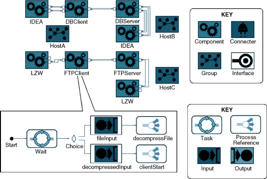
Figure 8-14. An example XTEAM model of a system comprising three hardware hosts and eight software components. The behavior of one of the components has been highlighted. This behavior represents XTEAM's syntactic overlay on top of FSP. XTEAM allows behaviors to be abstracted in the form of the ProcessReference construct.
Models conformant to the composed ADL contain sufficient information to implement a semantic mapping into low-level simulation constructs, which can be executed by an off-the-shelf discrete event simulation engine, such as adevs (Nutaro). This semantic mapping is implemented by XTEAM's model interpreter framework. When invoked by an architect, the XTEAM interpreter framework traverses the architectural model, building up a discrete event simulation model in the process. The interpreter framework maps components and connectors to discrete event constructs, such as atomic models and static digraphs. The FSP-based behavioral specifications encoded in XTEAM, such as the model shown in the bottom diagram of Figure 8-14, are translated into the state-transition functions employed by the discrete event simulation engine. The interpreter framework also creates discrete event entities that represent various system resources, such as threads. Hook methods provided by the framework allow an architect to generate the code needed to realize a wide variety of dynamic analyses.
XTEAM implements simulation-based analysis capabilities for end-to-end latency, memory utilization, component reliability, and energy consumption. Each analysis type requires the implementation of the needed XTEAM ADL extensions and a model interpreter. For example, XTEAM implements the component reliability modeling extension and analysis technique using the HMM-based approach discussed in Section 8.8.2. This reliability estimation approach relies on the definition of component failure types, the probabilities of those failures at different times during component execution, and the probability of, and time required for, recovery from failure. In order to support this type of analysis, XTEAM's FSP-based behavior language had to be extended to include failure and recovery events and probabilities. XTEAM was then augmented with an analysis technique that determines if and when failures occur as the components in the system progress through different tasks and states.
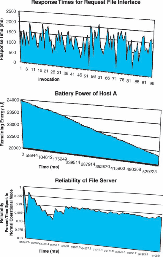
Figure 8-15. End-to-end latency, energy consumption, and reliability profiles of different elements of the architecture from Figure 8-14, obtained from adevs simulations. The simulations were generated automatically from the XTEAM model.
Another analysis supported by XTEAM is that of the modeled mobile system's energy consumption rate. The selected energy consumption model by Seo (Seo, Malek, and Medvidović 2007) was implemented as another XTEAM ADL extension and model interpreter, which incorporated the necessary elements of the energy cost model. Then, another adevs simulation was generated by XTEAM to show the system's likely energy consumption over time, under certain usage assumptions. The results of three different simulations for the architecture depicted in Figure 8-14 are shown in Figure 8-15.
A major part of what makes good architectural practice is deciding what one wants out of the architecture. An individual or organization cannot and should not focus on architecture just because it is widely accepted that doing so is the right thing to do. Instead, system stakeholders should first decide on the specific benefits they want to gain from the explicit architectural focus. One clear benefit of this is the establishment of a system's properties of interest before the system has been implemented and deployed. It is critical to make sure that the system possesses the key required properties and does not have or is reasonably unlikely to have any undesirable characteristics. Architectural analysis provides system stakeholders with a powerful suite of techniques and tools for doing that.
However, architectural analysis is neither easy nor cheap (see "The Business Case" sidebar). It should be planned for and applied carefully. The system's stakeholders must be clear about their project objectives and must map those objectives to specific architectural analyses. This chapter has provided a structure that can be used to determine the architectural analysis techniques that are best suited for specific system development scenarios. In many cases, multiple analysis techniques may need to be used in concert. Again, deciding which techniques to use is a critical part of an architect's job: using too many will expend the project's resources unnecessarily; using too few will run the risk of propagating defects into the final system; using wrong analyses will have both of these drawbacks.
Once a system's architecture is properly designed and modeled, and it is established through analysis that it possesses the desired properties, the architecture is ready to be implemented. Chapter 9 presents a detailed overview of architectural implementation challenges, techniques, and tools. Chapter 10 then discusses the software architectural implications in an implemented system's deployment and run time mobility. Chapter 14 will return to these issues in the context of architectural adaptation.
What are the four C s of architectural analysis?
What is the difference between internal and external consistency?
What is interface inconsistency? Provide an example.
What is interaction inconsistency? Provide an example.
What are the advantages and disadvantages of informal architectural models as pertaining to analysis?
What are the advantages and disadvantages of formal architectural models as pertaining to analysis?
Why is system-level analysis important if you have already completed component- and connector-level analysis?
Why is the analysis of the data exchanged in an architecture important?
Why is it important to analyze an architecture for non-functional concerns?
Who are the possible stakeholders in architectural analysis?
Is scenario-driven analysis a special case of static analysis or dynamic analysis? Justify your answer.
Name some advantages and disadvantages of architectural inspections and reviews.
What is model checking? How does it pertain to architectural analysis?
How does one analyze an architecture for deadlocks?
What are discrete-time Markov chains used for?
What is simulation?
If an architectural model is expressed in a notation that does not have executable semantics, can it still be simulated? Justify your answer.
Select one of the models of Lunar Lander from Chapter 4 or Chapter 6. Determine its components. For each individual component, model the services it provides and requires in terms of their names and interfaces. After you have completed the model, analyze the model manually for name and interface inconsistencies.
Model the behaviors of the Lunar Lander components used in the previous exercise, by specifying each component operation's pre- and post-conditions, as discussed in this chapter. After you have completed the model, analyze the model manually for behavioral inconsistencies.
As an alternative, or in addition to the pre- and postcondition based behavior model from the preceding exercise, model the Lunar Lander component behaviors with state-transition diagrams, such as those used by UML. Discuss the specific advantages and difficulties in using this model in ensuring behavioral consistency. Research whether any available techniques can be adopted or adapted for ensuring the consistency of two state-transition diagrams.
Select one of the models of Lunar Lander from Chapter 4 or Chapter 6. Determine its components. Construct each component's interaction model. Analyze these models for interaction inconsistencies. What, if any, are the differences between this task and the task described in the preceding exercise?
Download and study the Alloy modeling language and analysis tool suite (alloy.mit.edu). Discuss the possible ways in which Alloy can be used to aid architecture modeling and analysis. Demonstrate your arguments with specific examples of simple architectures, architectural properties, architectural styles, and so on.
Select an existing application with a documented architecture. This can be an application you have worked on or an open-source system. Study the architecture if you are unfamiliar with it. Follow the ATAM process to determine the quality attributes important to the system, as well as the architectural decisions employed. Develop a set of scenarios and key decisions underlying the architecture. Use the scenarios to determine whether the architectural decisions result in the required quality attributes.
Discuss the potential shortcomings of applying the ATAM process without all the prescribed stakeholders and a separate architecture evaluation team.
Select one of the models of Lunar Lander from Chapter 4 or Chapter 6. Provide its state-based reliability model as discussed in this chapter. Study an existing off-the-shelf technique for reliability estimation (such as DTMC or HMM). Apply this technique on your reliability model. Devise strategies for improving your system's reliability.
Select an important property of a software system, such as reliability, availability, or fault tolerance. State the assumptions required in order to be able to assess this property at the architectural level. Discuss the missing knowledge about the system that necessitates the assumptions. Then discuss the implications and reasonableness of each assumption.
Select two existing ADLs of your choice. Use each ADL to model the Lunar Lander architecture. Use the two ADLs' respective analysis tools to analyze each model for the properties on which the given ADL focuses. Discuss the extent to which the two ADLs' modeling features impact the available analyses versus the extent to which the selected analyses appear to impact the available modeling features.
Download and study an available simulation engine such as adevs (
www.ornl.gov/~1qn/adevs/index.html). Provide a mapping from an ADL of your choice to the simulation engine. Discuss the challenges in doing so and the range of architectural properties for which the simulations can be used. Practically demonstrate the use of simulation for at least one such property.
A significant amount of literature on software architecture has focused on architecture-based analysis. The early work on ADLs, such as Wright and Rapide, focused as much on the enabled analysis techniques as it did on the modeling features. Likewise, when UML first came onto the software development scene in the mid- to late-1990s as a de facto modeling standard, it was almost immediately accompanied by a continuing stream of publications on how UML models can be effectively analyzed for many different types of properties of interest. A widely cited overview of ADLs and their associated analysis capabilities was provided by Medvidović and Taylor in 2000 (Medvidović and Taylor 2000). That work has been recently revisited and the perspective expanded by Medvidović Dashofy, and Taylor (Medvidović, Dashofy, and Taylor 2007).
Carnegie Mellon University's Software Engineering Institute has, over time, proposed a number of architectural analysis approaches that entail inspections and reviews. Examples are ATAM, studied in this chapter; its precursor, Software Architecture Analysis Method, (SAAM); and an evaluation method for partial architectures, called ARID. These techniques are described in a book by Paul Clements, Rick Kazman, and Mark Klein (Clements, Kazman, and Klein 2002). Recently, Liliana Dobrica and Eila Niemelä provided a broader survey of inspection and review-based architectural analysis approaches (Dobrica and Niemelä 2002).
Leveraging explicit architectural models for determining a system's key non-functional properties has gained a lot of interest over time. This has resulted in a cross-pollination of ideas from established disciplines such as reliability, dependability, and fault-tolerant computing on the one hand, and software architecture on the other hand. In 2007 alone, Anne Immonen and Niemelä (Immonen and Niemelä 2007) have provided a survey of architecture-based methods for availability and reliability estimation, while Swapna Gokhale conducted a separate survey of architecture-based reliability analysis approaches (Gokhale 2007).