
As we have stated, every software system has an architecture, whether it is a "good" architecture or not. We have previously defined architecture as the set of principal design decisions about a system. Once design decisions have been made, they can be recorded. Design decisions are captured in models; the process of creating models is called modeling. From Chapter 3 we have:
Definitions. An architectural model is an artifact that captures some or all of the design decisions that comprise a system's architecture. Architectural modeling is the reification and documentation of those design decisions.
Models can capture architectural design decisions with varying levels of rigor and formality. They enable users to communicate about, visualize, evaluate, and evolve an architecture. Without models, architectures are inscrutable.
Throughout the chapter, we also discuss how architecture modeling notations are used to capture design decisions.
Definition. An architectural modeling notation is a language or means of capturing design decisions.
Available architecture modeling notations range from the rich and ambiguous (such as natural language) to the semantically narrow and highly formal (such as the Rapide architecture description language). While some models conform to a single notation, a model may also use a mix of different notations. For example, a single model may use the Unified Modeling Language (UML) class diagram notation to describe the classes in a system, but annotate them with natural language descriptions of their functions.
This chapter introduces a broad variety of modeling concepts that are captured in architectural models, from basic architectural elements (for instance, components and connectors) to more complex properties of systems such as behavioral models. It then covers some of the many available options for capturing different aspects of an architecture, from the semantically weak (such as PowerPoint modeling) to those with formal semantics. Finally, it discusses the strengths and weaknesses of some of these notations as applied to some of the systems we've discussed already, such as Lunar Lander and the World Wide Web.
Outline of Chapter 6
6 Modeling
6.1 Modeling Concepts
6.1.1 Stakeholder-Driven Modeling
6.1.2 Basic Architectural Concepts
6.1.3 Elements of the Architectural Style
6.1.4 Static and Dynamic Aspects
6.1.5 Functional and Non-Functional Aspects
6.2 Ambiguity, Accuracy, and Precision
6.2.1 Ambiguity
6.2.2 Accuracy and Precision
6.3 Complex Modeling: Mixed Content and Multiple Views
6.3.1 Views and Viewpoints
6.3.2 Consistency among Views
6.4 Evaluating Modeling Techniques
6.5 Specific Modeling Techniques
6.5.1 Generic Techniques
6.5.2 Early Architecture Description Languages
6.5.3 Domain- and Style-Specific ADLs
6.5.4 Extensible ADLs
6.6 When Systems Become Too Complex to Model
6.7 End Matter
6.8 Review Questions
6.9 Exercises
6.10 Further Reading
In this chapter, we discuss a broad spectrum of kinds of things that can be modeled in an architecture, and then discuss how various notations can be selected and used to facilitate this modeling. Specifically, for each concept we identify, we will identify what it takes to effectively model that concept—which notational features, and so on.
One of the most critical decisions that architects and others stakeholders will make in developing an architecture is to choose:
The architectural decisions and concepts that should be modeled.
The level of detail.
The amount of rigor or formality.
These decisions should be based on costs and benefits. Architects should balance the benefits of having certain models in certain forms or notations with the costs of creating and maintaining those models. Thus, the choice of what to model, and at what level of detail, will be stakeholder driven. A good rule of thumb is that the most important or critical aspects of a system should be the ones that are modeled in the greatest detail with the highest degrees of rigor/formality.

Figure 6-1, borrowed from Mark Maier and Eberhardt Rechtin's book, The Art of Systems Architecting (Maier and Rechtin 2000), graphically depicts this concept. It shows five concerns about the system identified by stakeholders. In this particular case, Concern 1 is of great importance, and will be considered and modeled deeply—in great detail. Concerns 2 and 4 are less important and will be modeled shallowly. Because the concerns and their relative levels of importance will vary from project to project, each project will have somewhat different modeling needs.
Modeling is an activity, and as such it is often governed by a process. It will undoubtedly be part of the larger process of architecture-centric software development that we have been discussing in this book. However, modeling itself is a subprocess, and the process of modeling can vary widely from project to project.
The basic activities behind stakeholder-driven modeling are to:
Identify relevant aspects of the software to model.
Roughly categorize them in terms of importance.
Identify the goals of modeling for each aspect (communication, bug finding, quality analysis, generation of other artifacts, and so on).
Select modeling notations that will model the selected aspects at appropriate levels of depth to achieve the modeling goals.
Create the models.
Use the models in a manner consistent with the modeling goals.
Although the steps outlined above are in rough chronological order, they can be incorporated into an iterative process. It is almost never clear from the outset of a project what all the important aspects of a software system are, what the goals of modeling are, and whether those goals are achievable using available notations, technology, time, and money. As such, these estimations must be reevaluated and refined multiple times through a system's development and the models and modeling efforts adjusted accordingly.
While each architecture is different, we have previously identified (particularly in Chapter 4) certain kinds of elements that are of importance when talking about architectural designs. These include the following.
Components. Components are the architectural building blocks that encapsulate a subset of the system's functionality and/or data, and restrict access to them via an explicitly defined interface.
Connectors. Connectors are architectural building blocks that effect and regulate interactions among components.
Interfaces. Interfaces are the points at which components and connectors interact with the outside world—in general, other components and connectors.
Configurations. Configurations are a set of specific associations between the components and connectors of a software system's architecture. Such associations may be captured via graphs whose nodes represent components and connectors, and whose edges represent their interconnectivity.
Rationale. Rationale is the information that explains why particular architectural decisions were made, and what purpose various elements serve.
These concepts form a starting point for architectural modeling. At the most basic level, modeling these concepts requires a notation that can express a graph of components and connectors, preferably with well-defined connection points (interfaces). These languages can be relatively simple—basic box and arrow diagrams or lists with appropriate internal references will suffice. Rationale is somewhat different because it is more amorphous. Rationale is primarily used for communicating information and intent among stakeholders, and is generally not represented explicitly in the actual, built software system. As such, languages for expressing rationale need to be more expressive and less constrained—rationale is most often expressed using natural language for this reason.
Modeling at only the most basic level (that is, enumerating the existence and interconnections of the various components and connectors) provides a small amount of value, but these models will not suffice for most complex projects. Rather, these models must be extended and annotated with a host of other concepts: How are the functions partitioned among the components? What are the nature and types of the interfaces? What does it mean for a component and a connector to be linked? How do all these properties of a system change over time? These questions are at the heart of architectural modeling.
Depending on the nature of the system being developed and the domain, it may or may not be straightforward to represent these basic elements. For example, in a desktop application such as a word processor or spreadsheet, the software components and connectors will be relatively static and few in number. Even with a very complex desktop application containing, say, 500 to 1000 components and connectors, it is feasible to enumerate and describe each of these elements as well as the interconnections among them.
Applications that are large, dynamic, and distributed may be harder to model. For example, it is basically impossible to enumerate all the software components that are part of the World Wide Web or their configuration: There are too many of them and they are constantly coming and going. For these applications, it is probably more reasonable to model only parts of the system, or specific configurations that represent expected use cases. Alternatively, it may be more effective to model the architectural style that governs what kinds of elements may be included in the architecture and how they may be configured.
Recall that an architectural style is a collection of architectural design decisions that are applicable in a given development context, constrain architectural design decisions that are specific to a particular system within that context, and elicit beneficial qualities in each resulting system. In addition to modeling basic architectural elements, it is often useful to model the style that governs how these elements have been (and may be) used.
Note that architectural styles, like architectures, are made up of design decisions. These design decisions can also be modeled. Explicitly modeling the architectural style can be helpful for a number of reasons. It reduces confusion about what is and is not allowed in the architecture. It can help to reduce architectural drift and erosion. It makes it easier to distinguish whether a specific design decision in an architecture was made to conform to a stylistic constraint or for some other reason. It can help to guide the evolution of the architecture. It can be more feasible and useful than structural modeling (component and connector graphs) for large or dynamic systems. Because styles are generally applicable to many projects, style models can be reused from project to project. Styles represent a single place to capture cross-cutting concerns and rationale for an architecture.
The kinds of design decisions found in an architectural style are generally more abstract or general than those found in an architecture. Some kinds of design decisions that might be captured in a style model include:
Specific Elements. A style may prescribe that particular components, connectors, or interfaces be included in architectures or used in specific situations. This can be facilitated by a modeling approach that supports templates or base models that are then elaborated.
Component, Connector, and Interface Types. Specific kinds of elements may be permitted, required, or prohibited in the architecture. Many modeling approaches are accompanied by a type system, although they often have different semantics.
Interaction Constraints. Constraints on interactions between components and connectors may exist. These constraints can take many forms. They may be temporal ("calling components must call init() before any other method"). They may be topological ("only components in the client layer are allowed to invoke components in the server layer"). They may specify particular interaction protocols, either by name (FTP, HTTP) or specification (formal protocol specifications in a language such as CSP or sequence charts). Modeling approaches that support constraints generally leverage some sort of logic—first-order logic, temporal logic, and so on.
Behavioral Constraints. Constraints on the behavior of architectural elements, or kinds of elements, may be included. Constraints can run the gamut from simple rules to full-blown complete behavioral specifications for components expressed in a notation such as finite state automata. Here again, modeling approaches that support behavioral constraints use either logic or other formal models (such as automata diagrams).
Concurrency Constraints. Constraints on which elements perform their functions concurrently and how they synchronize access to shared resources can also be included in an architectural style. Approaches that support concurrency modeling often employ formal behavioral models of various architectural elements; many also include temporal modeling techniques, such as sequence charts and statecharts.
Architectural design decisions may address both static and dynamic aspects of a system. Static aspects of a system are those that do not involve the system's behavior while it is executing. Dynamic aspects of a system involve the system's runtime behavior.
Static aspects are generally easier to model simply because they do not involve changes over time. Typical models of static system aspects might include component/connector topologies, assignments of components and connectors to processing elements or hosts, host and network configurations, or mappings of architectural elements to code or binary artifacts.
Dynamic aspects of a system can be harder to model because they must deal with how a system behaves or changes over time. Typical models of dynamic aspects may be behavioral models (describing the behavior of a component or connector over time), interaction models (describing the interactions between a set of components and connectors over time), or data flow models (describing how data flows through an architecture over time).
The static/dynamic distinction is often not a clear line. For example, a system's structure may be relatively stable, but may change occasionally due to component failure, the use of flexible connectors, or architectural dynamism (see Chapter 14). In these cases, models that capture both static and dynamic system aspects may be employed: For example, a (static) base topology may be accompanied by a set of transitions that describe a limited set of changes that may occur to that topology during execution.
There is an important distinction between modeling static and dynamic aspects of a system and using static or dynamic models. The former refer to properties of the system being modeled. The latter refer to changes to the models themselves. A model of a dynamic aspect of a system describes how the system (often, its internal state) changes as it executes. A dynamic model actually changes itself.
Dynamic models are not necessary to capture dynamic aspects of a system. Consider a statechart. A statechart can capture the behavior of a component over time (a dynamic aspect), but the statechart itself does not generally change (for example, acquire new nodes or transitions) as the component executes. If the statechart were connected to a running system such that the current state of the system was always highlighted in the statechart, then the statechart would become a dynamic model. Such a statechart would be useful for visualizing the behavior of an application, perhaps for debugging purposes.
Supporting dynamic models is more difficult than supporting static models. Once developed, static models can be incorporated into a system in "read-only" mode—they are static resources that can be used as a basis for implementation, comparison, and analysis. Dynamic models must be incorporated in "read-write" mode—the system's execution can change the model itself. This requires tool support to keep the model and the system synchronized and consistent. For these mechanisms to operate automatically, the model must be stored in a machine-readable and writable form, and the model must be appropriately mapped to the implemented system. Visualizations of the model must also be suitably dynamic, reflecting changes to the model on-the-fly if possible.
Architecture can capture both functional and non-functional aspects of a system. Functional aspects relate to what a system does. Non-functional aspects relate to how a system performs its functions. A good rule of thumb for thinking about this distinction is that functional aspects of a system can be described using declarative, subject-verb sentences: The system prints medical records. Non-functional aspects of a system can be described by adding adverbs to these sentences: The system prints medical records quickly and confidentially. An extensive survey of non-functional properties from an architectural perspective is contained in Chapter 12.
Because functional aspects are generally more concrete, they are easier to model and can often be modeled rigorously and formally. Typical functional models of a system might capture the services that are provided by different components and connectors and the interconnections that achieve the overall system functions. They may capture the behavior of components, connectors, or subsystems, describing what functions those elements perform. Functional aspects of a system can be static or dynamic.
Most modeling notations focus on capturing functional aspects of systems. Notations and approaches differ in the aspects of a system that can be described, and how. Any selected notation or modeling approach must employ a sufficient number of concepts to express the aspect; the underlying semantics of the approach will determine the kinds of reasoning and analysis that can be applied.
Non-functional aspects of systems tend to be qualitative and subjective. Models of non-functional aspects of systems may be more informal and less rigorous than functional models, but this does not mean they should not be captured. Often, functional aspects of systems are developed specifically to correspond with or achieve non-functional objectives. For example, a non-functional model might simply prescribe that the paycheck-processing component be fast. The functional model of the paycheck component may describe how the paycheck-processing component uses caches and local processing—two functional strategies that help to achieve the modeled non-functional aspect.
Much like design rationale, non-functional aspects of systems are difficult to model with rigor. Expressive, free-form notations such as natural language are often used for capturing non-functional aspects. It is useful, however, to employ approaches with support for traceability, which allow modelers to explicitly map non-functional properties to functional design decisions.
Architectures are abstractions of systems. They capture information about some aspects of the system and leave out other aspects. Ideally, the principal, most important aspects of a system will be well defined by the architecture. The parts that are specified may describe the nominal state of the system and leave out unusual states. This is, to some extent, normal: Architectures are not meant to be complete implementations of a system. Consequently, the notations used to capture architectures do not have to be completely unambiguous, accurate, and precise.
Three key concepts can be used to characterize architectural models: ambiguity, accuracy, and precision.
Because conflicting interpretations of a model may lead to misunderstandings, bugs, and errors, it is generally desirable to eliminate ambiguity in design. Incompleteness is a primary reason for ambiguity in models: When some aspect of a system is left unspecified, different stakeholders may make different assumptions about how the gap should be filled in. Architectures are necessarily incomplete: They address principal design decisions about a system, not every design decision.
For this reason, it is generally impossible to completely eliminate ambiguity in architectural models. Additionally, the costs of attempting to do so will nearly always outweigh the benefits. Therefore, a balance must be struck. A good guideline is to allow aspects of the system to be ambiguous with the consent of appropriate stakeholders, proceeding when they agree that the architecture is "complete enough" and remaining decisions can be made in a future development activity. While this evaluation proceeds, it is useful to specifically identify and document ambiguous aspects of the architecture as a kind of design rationale.
Many conceptions of accuracy and precision, including dictionary definitions, conflate the two terms. Here, we will adopt an interpretation that more clearly delineates them.
Definition. A model is accurate if it is correct, conforms to fact, or deviates from correctness within acceptable limits.
Definition. A model is precise if it is specific, detailed, and exact.
Accuracy deals with correctness, while precision deals with exactness. In architectural terms, a model is accurate if it conveys correct information about the modeled system. A model is precise if it conveys a lot of detailed information about the modeled system. It may seem as if these concepts go hand in hand, but in fact they are somewhat orthogonal.
Figure 6-2 graphically depicts the distinction between accuracy and precision as a set of targets that have been shot. Consider each shot to be an assertion about a system being designed. Figure 6-2(a) shows a set of shots (assertions) that are neither accurate nor precise: they are not close together and are not near the target. Architecturally, this represents design decisions that are both incorrect (that is, inaccurate) and vague or general (that is, imprecise). Figure 6-2(b) shows shots that are accurate, but not precise: They are clustered around the target, but are not close together. These assertions are accurate (correct) but vague and lacking detail. Architecturally, this might be a result of ambiguity or correct descriptions of only a few aspects of the system. Figure 6-2(c) shows shots that are precise, but not accurate: They are clustered close together, but they are not near the target. This could be interpreted as assertions about the system that are highly detailed, but wrong. Figure 6-2(d) shows shots that are both precise and accurate: The assertions are both detailed and correct.

In developing an architecture, accuracy should generally be favored over precision. Precision and completeness are, of course, desirable, but later phases of detailed design and implementation will necessarily flesh out the missing detail. However, inaccurate architectural models that mislead stakeholders in these later phases will generally lead to costly errors in later development activities.
Notations and modeling approaches can have a significant effect on the ambiguity, accuracy, and precision of models. Some notations include elements that are purposefully ambiguous—they allow stakeholders to interpret their meaning in the manner most useful to their project. Other notations are based on formal semantics, and encourage less ambiguous and more precise specifications. In these approaches, the designers specify what each element means and how it should be interpreted. Often, these interpretations are built directly into visualization and analysis tools.
Stakeholders can find utility in all kinds of modeling approaches, from the ambiguous and imprecise to those with formal semantics. Approaches that promote reduced ambiguity and increased accuracy and precision are often more costly to use because they have higher learning curves and require more detailed modeling. For these reasons, stakeholders should generally choose notations that allow unambiguous, accurate, and precise modeling of the aspects of the system that are the most important. Other approaches can be used for less important aspects of the system. Since no notation will be ideal for modeling every aspect of a system, combinations of notations should generally be used to capture an architecture.
Architecture models are complex artifacts. They attempt to capture all the design decisions about a system that are important to a wide variety of stakeholders. Additionally, different aspects of the same concept will be captured simultaneously, for example, a component's interconnections to other components, its behavior, and its version history. There is simply too much information to deal with all at once, and attempting to do so is not productive: Stakeholders generally want to interact with the parts of the architecture that are most important from their own perspective.
In general, no single approach will be able to capture all the aspects of an architecture for a project. This means that various parts of the architecture may have to be modeled using different approaches. For example, non-functional aspects of a system may be captured using natural language, structure with a component-connector graph, and various component behaviors with statecharts.
This situation induces the notion of views and viewpoints.
Definition. A view is a set of design decisions related by a common concern (or set of concerns).
Definition. A viewpoint defines the perspective from which a view is taken.
A view is an instance of a viewpoint for a specific system. Put another way, a viewpoint is a filter for information, and a view is what you see when you look at a system through that filter. For example, consider the domain of systems in which software components are distributed across multiple hosts. The deployment viewpoint is a perspective on such systems that captures design decisions related to how components are assigned to hosts. The deployment view of a particular system captures how components are assigned to hosts for that particular system.
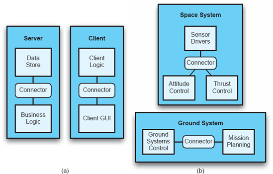
Figure 6-3 shows the deployment views of two different systems. Figure 6-3(a) shows the deployment view of a client-server system. Figure 6-3(b) shows the deployment view of a distributed space-ground system like Lunar Lander. However, both of these views are taken from the deployment viewpoint; that is, they both capture design decisions dealing with the deployment of components onto hosts.
In general, viewpoints are associated with one concern. Examples of viewpoints that are commonly captured include:
Logical Viewpoint: Captures the logical (often software) entities in a system and how they are interconnected.
Physical Viewpoint: Captures the physical (often hardware) entities in a system and how they are interconnected.
Deployment Viewpoint: Captures how logical entities are mapped onto physical entities.
Concurrency Viewpoint: Captures how concurrency and threading will be managed in a system.
Behavioral Viewpoint: Captures the expected behavior of (parts of) a system.
It is also possible for multiple views to be taken from the same viewpoint for the same system. That is, there might be multiple deployment views for a single system, with different levels of detail. One view might show only top-level components, while another might show both top-level components as well as subcomponents and additional internal structure.
The use of views and viewpoints in modeling is important for several reasons:
They provide a way to limit presented information to a cognitively manageable subset of the architecture.
They display related concepts simultaneously.
They can be tailored to the needs of specific stakeholders.
They can be used to display the same data at various levels of abstraction.
Often, the same or related information will be present in two or more views. This immediately gives rise to an important question: How does one know whether two views are consistent with each other? This requires a definition of consistency with respect to architectural views.
Views are consistent if the design decisions that they contain are compatible. Alternatively, consistency can be seen as the absence of inconsistency. An inconsistency occurs when two views assert design decisions that cannot both be simultaneously true. Many kinds of inconsistency can arise. Some kinds of inconsistency that might occur in a multiple-view architecture description include the following.
Direct Inconsistencies. These inconsistencies occur when two views assert directly contradictory propositions such as "the system runs on two hosts" and "the system runs on three hosts." These inconsistencies can often be detected by automatic mechanisms that employ appropriate constraints and rules.
Refinement Inconsistencies. These inconsistencies occur when two views of the same system at different levels of detail assert contradictory propositions. For example, a "top level" structural view contains a component that is absent from a structural view that includes subarchitectures. These inconsistencies can also be automatically detected with appropriate consistency rules, provided both the top-level and refined views contain enough information to understand the relationship between the two.
Static Aspects versus Dynamic Aspects. In this inconsistency, a view of a static aspect of a system conflicts with a view of a dynamic aspect. For example, a message sequence chart view might depict the handling of messages by a component that is not contained in the structural view. These inconsistencies can be somewhat harder to automatically detect, depending on how explicit the dynamic aspect's specification is.
Dynamic Aspects. In this inconsistency, two views of dynamic aspects of the system conflict. For example, a message sequence chart depicts a specific interaction between components that is not allowed by the behavioral specifications contained in those components' statecharts. These inconsistencies are often extremely difficult to detect automatically because it would require extensive state exploration or simulations.
Functional versus Non-Functional Aspects. These inconsistencies occur when a non-functional property of a system prescribed by a non-functional view is not met by the design expressed in functional views. For example, a non-functional view of a client-server system may express that the system should be robust, but the physical view of the system may show only a single server with no evidence of failure-handling machinery. These inconsistencies are the most difficult to detect because of the general and abstract nature of non-functional properties.
Figure 6-4 shows two hypothetical views of a distributed Lunar Lander system. The physical view (a) depicts three hosts, a Ground System, a Command Module Computer, and a Lander Computer. However, the deployment view (b) shows components assigned to only two hosts, a Ground System and a Lunar Lander. It is fairly easy to see that something is not right here—there is an inconsistency between the physical and deployment view. The inconsistency fits our above definition—the physical view asserts the design decision that Lunar Lander runs on two hosts, while the deployment view asserts the decision that Lunar Lander runs on three.
This inconsistency is relatively easy to spot just by looking. However, other, more subtle inconsistencies (such as inconsistencies between different behavioral specifications of an architecture) are harder to detect and more costly to fix.

Detecting, identifying, and resolving inconsistencies among views is a difficult problem. First, stakeholders must agree on what "consistency" means for their particular choice of views and modeling notations. Then, strategies must be employed to locate and deal with inconsistencies. These can range from manual approaches such as inspections and checklists to automated approaches such as model checking and simulation. Chapter 8, which covers architectural analysis, discusses in detail specific approaches for dealing with inconsistency.
Inconsistency is generally, but not always, undesirable. Inconsistencies will arise as a natural part of doing exploratory design—as you design an architecture, parts of it may be temporarily inconsistent as the design evolves. Sometimes, inconsistencies are left in an architecture deliberately upon agreement of the stakeholders to deal with a special case, or because repairing the inconsistency would be too costly.
In the past sections, we have explored a number of dimensions that can be used to characterize different modeling techniques. These dimensions can be turned into a rubric for critically thinking about and evaluating different modeling techniques. This rubric will be applied to several techniques in the remainder of this chapter.
Architects have at their disposal a panoply of notations and techniques for modeling different aspects of architectures. These techniques vary along many dimensions: what they can model, how precisely they can capture architectural semantics, how good their tool support is, and so on. Which methods are used, and for what purposes, will be largely up to a system's architects and stakeholders. While many approaches for modeling architectures are broadly scoped and applicable to many systems in many domains, it is important not to become dogmatically attached to any one approach.
The next sections discuss and evaluate various approaches that can be used for modeling software architectures. A simple version of the Lunar Lander system is used as a running example to illustrate and compare modeling techniques.
These techniques are often used to describe a software architecture in whole or in part, although they were not specifically developed or adapted for this purpose. As such, they tend to be flexible but have few semantics.
Natural languages, such as English, are an obvious way to document architectural design decisions. Natural languages are expressive, but tend to be ambiguous, nonrigorous, and nonformal. Natural language cannot be effectively processed and understood by machines, and thus can only be checked and inspected by humans.
Despite these drawbacks, natural-language modeling can be the best way to capture some aspects of an architecture. For example, non-functional requirements are often captured using natural language since they are abstract and qualitative. Natural language is easily accessible to stakeholders and can be manipulated with common tools such as word processors.
An alternative to using pure natural language is to use a restricted form of it. Users can create and consistently employ a dictionary of terms in order to limit certain kinds of problems (for instance, ambiguity that can arise from using different terms for the same concept, or lack of clarity). Statement templates, which are natural language statements or paragraphs with fill-in-the-blanks parameters can be another way to increase rigor in natural language. However, overusing this strategy has a negative effect—essentially, it creates a domain-specific language without any of the flexibility benefits of natural language.[8].
Here, we introduce a simple three-component version of the Lunar Lander application that will be used throughout the remainder of this chapter to illustrate the use of different modeling approaches.
The Lunar Lander application might be described in natural language as shown in Figure 6-5, which provides a fairly significant amount of information about the Lunar Lander system. For example, the structure of the components and their dependencies is explicitly stated, as well as a description of their behaviors, inputs, outputs, and general responsibilities. The description stops short of specifying certain details that are required for implementing the system. For example, it does not explain the algorithm the calculation component uses for its computations, the particular formats of the different data values, anything about the connectors between the components, or what the user interface should look like.
Many different implementations could satisfy this architectural description, and they may not all function identically. This is partially due to the nature of architectural models in general—they document principal design decisions, not all design decisions. It is also partially due to the ambiguity inherent in natural language specifications. This specification is not the tersest or most understandable way of expressing aspects of this system such as its structure—readers of the specification are likely to build up a mental graph of the system's constituent components as they read, since one is not provided.

Takeaways. Natural language should be used as an adjunct to more rigorous and formal languages, for aspects of architecture where formalism is infeasible or unnecessary. It is particularly good for specifying non-functional properties in a way that almost no other language can match.
Tools such as Microsoft PowerPoint (Microsoft Corporation 2007) and OmniGraffle (The Omni Group 2007) provide users with the ability to create decorative diagrams of interconnected shapes through a point-and-click graphical interface. These are ubiquitous and it is easy to use them to create aesthetically pleasing diagrams. The size limitations of such diagrams (one slide, one sheet of paper) help to ensure that they remain suitably abstract.
Informal graphical notations have a lot in common with natural languages—they provide informal, unconstrained ways of expressing ideas (although they primarily use symbols rather than words). Informal graphical diagrams often capture few (if any) semantics. This makes it difficult to reliably interpret the meaning of the diagrams, undermining the key advantages of using an architecture in the first place (communication, analysis, and so on). These diagrams are good for early prototyping and exploration, capturing ideas at an abstract, conceptual level. However, they lack the rigor required for more concrete models.
Lunar Lander in PowerPoint. There are many ways to express the Lunar Lander architecture in a tool like Microsoft PowerPoint, limited only by the symbol palette available in the tool.
A Lunar Lander architectural model in PowerPoint is shown in Figure 6-6. As with most PowerPoint architecture diagrams, the particular symbology used is not directly explained—there is no underlying semantic model (other than the reader's expectations) through which to interpret this diagram. The meanings of the three-dimensional boxes, the arrows, and the rounded rectangles are not provided. More serious modeling efforts might provide a symbolic dictionary to accompany such a diagram. However, this can be dangerous: Even when users employ consistent or well-understood symbols, informal diagramming tools cannot provide automated consistency checks or analysis.

The intended interpretation of this particular diagram is that the three-dimensional boxes are software components, the arrows indicate invocation dependencies, and the rounded rectangles are commentary on the intended behavior and responsibilities of the components. Assuming that the reader correctly interprets the meanings of the symbols, this model is in certain ways easier to understand than the natural language model. For example, the componentization of the system and the component dependencies are immediately obvious, and the behaviors are visually connected to the components.
Takeaways. PowerPoint and similar tools are seductive because they make it very easy to create graphical diagrams. However, great care should be taken in using informal graphical diagrams as part of any official architecture description—they can be valuable for early back-of-the-napkin architecture descriptions, but as soon as basic decisions are made, more rigorous notations should be employed for real architecture capture.
UML, the Unified Modeling Language (Booch, Rumbaugh, and Jacobson 2005), is the most popular notation for writing down software designs. It is unified in that it combines concepts from earlier notations such as Booch diagrams (Booch, 1986), James Rumbaugh's OMT (Rumbaugh et al. 1990), Ivar Jacobson's OOSE (Jacobson 1992), and David Harel's Statecharts (Harel 1987). UML's main strengths are its large variety of modeling constructs and viewpoints, extensive tool support, and widespread adoption.
UML is a massive notation about which entire books can be and have been written. We summarize its role as an architectural modeling language here. Further information about UML as a standard for software and system modeling is presented in Chapter 16.
UML is an inherently graphical notation, with views consisting of textually annotated graphical symbols. It provides its users with an extremely wide variety of modeling constructs and concepts. UML 2.0 includes thirteen different viewpoints, called "diagrams" in UML parlance. These viewpoints cover many of the dimensions identified earlier in this chapter, including basic architectural elements, stylistic constraints, and static and dynamic aspects of systems.
Much debate has ensued over the years as to UML's suitability for modeling software systems at the architecture level. Early versions of UML (1.0 and 1.1) (Booch, Rumbaugh, and Jacobson 1998) had a strong focus on detailed design—below the level of common architectural constructs such as components and connectors. They were biased toward the design of object-oriented systems that communicate primarily through procedure calls. UML 2.0 significantly expanded UML to provide much better support for higher-level architectural constructs. Existing viewpoints were extended with new elements and entirely new viewpoints were added.
UML's broad range of diagrams makes it an attractive option for modeling all kinds of software systems. However, it is vitally important for architects not to get locked in to UML as their one and only modeling solution for architectures, or to overestimate the benefits conferred by using UML.

UML's viewpoints remain mostly focused on design. In many ways, these viewpoints still retain an inherent bias toward object-oriented systems. Some of the viewpoints extend into other life cycle activities, capturing some requirements- and implementation-related aspects. Explicit support is minimal for activities such as testing and maintenance and meta-activities such as management. Architectural decisions can affect any of these aspects of development; this is why additional notations should be used to capture a complete architecture.
Understanding the semantics of UML diagrams is key to making them useful in describing architectural design decisions. UML is more precise than arbitrary diagrams that would be produced in, say, PowerPoint. However, it has been designed to be purposefully ambiguous in many respects so as to increase its generality.
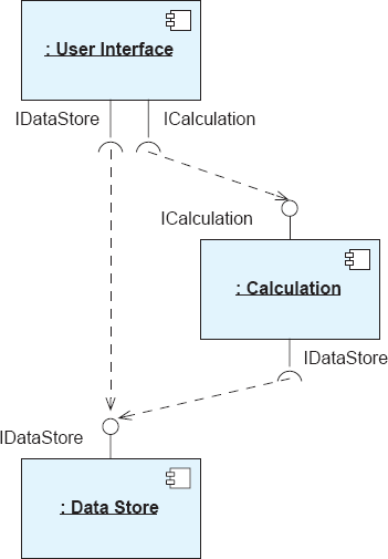
For example, the dashed open-headed arrow is a "dependency" arrow. It indicates that the element at the tail of the arrow has some dependency on the element at the head of the arrow. Figure 6-7 shows a simple UML component diagram with two components. The dashed arrow indicates that the Calculation component is dependent on the Data Store component. However, this could mean any number of things, including:
Some element of Calculation calls Data Store.
Instances of Calculation contain a pointer or reference to an instance of Data Store.
Calculation requires Data Store to compile.
Calculation's implementation has a method that takes an instance of Data Store's implementation as a parameter.
Calculation can send messages to Data Store.
And so on, and so on. Most constructs in UML are similarly semantically ambiguous. (It is even unclear what the components in Figure 6-7 refer to: They could be classes in an object-oriented programming language, C modules, Web services, or something else.)
This approach gives UML great flexibility but limits its semantic precision. Fortunately, UML includes facilities that allow its users to define new attributes (called stereotypes and tagged values) and constraints that can be applied to existing elements to specialize them. Constraints in UML can be specified in any language (including natural language), but a companion language called the Object Constraint Language (OCL) provides a convenient way to write rigorous constraints for UML. A collection of these additional attributes and constraints is known as a UML profile. Profiles are generally designed for specific applications, product lines, or domains, and serve to increase the semantic precision of UML diagrams within that scope.

Figure 6-8 shows two variants of the component diagram in Figure 6-7. Each of these uses a UML stereotype to provide additional detail about the meaning of the dependency arrow. This does not make the dependency arrow completely unambiguous, however—understanding it still relies on the reader's interpretation of "import" or "call." The top diagram indicates that Calculation imports Data Store. The bottom diagram indicates that Calculation calls Data Store. The available selection of stereotypes and their specific meanings are defined by the UML profile in use.
UML diagrams alone do not carry enough information to completely interpret them. Stakeholders may make agreements among themselves about how to interpret particular aspects of UML diagrams on a project and document these agreements in external natural-language documents. Stakeholders should also strongly consider defining or selecting a profile with documented interpretations for the included stereotypes, tagged values, and constraints.
Lunar Lander in UML. UML provides many possible viewpoints from which to model the Lunar Lander architecture. Stakeholders are responsible for choosing which viewpoints are used and how precise each view will be. Here, we will use the component, statechart, and sequence viewpoints to describe the Lunar Lander at roughly the same level of detail as has been shown in the natural language and informal graphical examples.
The component diagram for Lunar Lander might look like Figure 6-9.[9] This diagram looks very similar to the informal graphical diagram, because it largely depicts the same aspect of the architecture. Unlike the informal graphical diagram, though, this diagram has a rigorous syntax and some underlying semantics. The symbols used are documented in the UML specification, and have specific meanings. Unlike the unadorned three-dimensional boxes intended to represent components in the PowerPoint view of Lunar Lander, the well-defined UML "component" symbol is used here. This is not to say that the diagram is completely unambiguous—for example, the diagram says nothing about what a component is in this context, or when and how the calls among components are made. Some of these details can be specified in other UML diagrams.

The behavior of the system might be specified in a UML statechart diagram, as shown in Figure 6-10. The start state is indicated by the plain dark circle, and the end state is indicated by the outlined dark circle. Each rounded rectangle represents a state of the system, and arrows represent transitions between the states. The conditions in square brackets indicate guards that constrain when state transitions may occur.
This statechart indicates that the Lunar Lander system begins by displaying the lander state. If the simulation is done, the simulator will stop. Otherwise, the system will request a burn rate from the user. Here, the user may choose to end the program early. Otherwise, if the burn rate is valid, the program will then calculate the new simulator state and display it. This control loop will repeat until the simulation is done.
While this statechart diagram provides a more rigorous and formal description of the system behavior than either the natural language or informal graphical architecture description, it leaves out some important details contained in both those descriptions—namely, which components perform the specified actions. This information can be captured in another UML diagram, such as a UML sequence diagram.
A sequence diagram for the Lunar Lander application might look like Figure 6-11. This diagram depicts a particular sequence of operations that can be performed by the three Lunar Lander components. Sequence diagrams such as this one are not intended to capture all the behavior of a system; rather, they are used to document particular scenarios or use cases. The above diagram depicts one nominal scenario—User Interface gets a burn rate from the user, Calculation retrieves the state of the lander from the Data Store and updates it, and then returns the termination state of the lander to User Interface.

Figure 6-9, Figure 6-10, and Figure 6-11 represent three different views of the Lunar Lander architecture. These views capture both static (structural) and dynamic (behavioral) aspects of the system. A natural question to ask is whether these views are consistent with one another. There is no standard way to answer this question, as there is no universal notion of consistency in UML. Instead, we have to establish our own criteria for consistency and check the views against these criteria. For example, we could check whether each component in the component diagram is represented in the sequence diagram, and whether the calls in the sequence diagram are allowed by the dependency arrows in the component diagram.
Checking the consistency of the statechart and sequence diagrams is a more difficult task. These two diagrams model behavioral aspects of the architecture at substantially different levels. The statechart describes the overall functioning of the system without regard to its structure, while the sequence diagram shows a particular scenario in a different context: the interactions between components. In this case, inspections and stakeholder agreement are probably the best way to determine the consistency of the diagrams.
Takeaways. UML is a syntactically rich notation with extensive tool support. As a way of expressing architectural design decisions, it is superior to a symbols-only notation such as PowerPoint's. However, UML's purposeful ambiguity about the meaning of most of its symbols leaves it open for abuse. Even well-intentioned development groups can interpret the same UML diagrams in different ways, especially when stakeholders are geographically separated and do not have face-to-face opportunities to come to a mutual understanding. When UML is employed, profiles must be developed and used to ensure consistent modeling, although this does not necessarily guarantee unambiguous interpretations. Profiles are not a panacea.
The 1990s spawned nearly a decade of research on how to best capture software architectures. The result of this research was a proliferation of architecture description languages (ADLs), notations developed specifically for software architecture modeling.
During this period, there was substantial debate over what does and does not constitute software architecture. This debate continues today. A parallel debate naturally emerged: Which notations or modeling approaches can be called "architecture description languages?" There is no established litmus test to determine whether a particular notation can or cannot be called an ADL, and there is significant variability in the spectrum of languages that are identified by their creators as ADLs. Nenad Medvidović and Richard Taylor (Medvidović and Taylor 2000) surveyed a wide variety of early ADLs and found that the common denominator among them was explicit support for modeling:
Components.
Connectors.
Interfaces.
Configurations.
Additionally, they found that languages identified as ADLs tended to be semantically precise but lacked breadth and flexibility. This largely mirrored the prevailing sentiment about software architecture; namely, that it was a high-level structural view of a system extended with rich semantics.
This book takes a much broader view on software architecture. While high-level component-and-connector views are still important when describing a software system's architecture, our definition of architecture as the set of principal design decisions about a system encompasses a much broader range of concepts.
During the 1990s, there was significant debate about whether design notations like UML could be called "architecture description languages." Early versions of UML lacked explicit support for component-and-connector style modeling as well as precise semantics, leading many researchers to conclude that UML was not, in fact, an architecture description language. In our broader conception of architecture, any language used to capture principal design decisions is effectively an architecture description language, including UML.
The early "first-generation" architecture description languages described in this chapter are, for the most part, research projects. None of these is still used actively in practice. We present them here because of their unique contributions to the field of architecture modeling, but their use in practice may prove difficult for extrinsic reasons, such as lack of current tool support.
Darwin (Magee et al. 1995) is a general-purpose architecture description language for specifying the structure of systems composed from components that communicate through explicit interfaces. Darwin has a canonical textual representation in which components and their interconnections are described. There is an associated graphical visualization that depicts Darwin configurations in a more accessible but less precise way.
In Darwin, systems are modeled as a set of interconnected components. There is no notion of explicit software connectors in Darwin, but a component that facilitates interactions could be interpreted as a connector. Darwin components expose a set of provided and required services, sometimes called ports. Services in Darwin correspond to our notion of provided and required architectural interfaces. Configurations are specified by a set of bindings between interfaces. Darwin also has support for hierarchical composition—that is, components that have internal structures also consisting of components, services, and bindings.
Lunar Lander in Darwin. Darwin is primarily a structural description notation, and we can use it to describe the three-component Lunar Lander's structure. The textual visualization of Lunar Lander in Darwin might be expressed as shown in Figure 6-12. Here, each component is described with explicit provided and required interfaces. The overall application structure is defined using a top-level component with an internal structure; that is, the Lunar Lander application itself is a component containing the UserInterface,Calculation, and DataStore components.

As stated above, Darwin also has a canonical graphical visualization; the model expressed in that visualization might look like Figure 6-13. The use of multiple visualizations to depict the same architectural model will be discussed extensively in the next chapter.
One of the most interesting aspects of Darwin is the set of constructs with which configurations of components can be specified. Many declarative ADLs simply enumerate all the components and bindings in an architecture one by one (and Darwin supports this—the above model of Lunar Lander uses Darwin in this way). However, Darwin also supports the creation of configurations using programming-language-like constructs such as loops. For example, consider a Web application where a number of identical clients are all connecting to the same Web server. We might model this architecture in Darwin shown in Figure 6-14.
Graphically, this model might look like Figure 6-15. In this Darwin model, the actual number of clients is parameterizable. Using these facilities, relatively terse models can be constructed that describe a wide variety of architectures without a great deal of redundancy in the model.
Takeaways. Darwin represents a more rigorous and formal way of capturing an architecture's structure than any notation we have seen thus far in the chapter. It provides a well-defined textual syntax with an associated graphical visualization, along with specific, well-defined semantics. It is not overly complex and can be understood by straightforward reading. For structural modeling, Darwin is an excellent choice. For modeling other aspects of architecture, however, other notations should be used.


Rapide (Luckham et al. 1995) is an architecture description language developed to specify and explore dynamic properties of systems composed of components that communicate using events. In Rapide, events are simply the result of an activity occurring in the architecture. Traditional procedure calls are expressed as a pair of events: one for the call and one for the return value.
The power of Rapide comes from its organization of events into partially ordered sets, called POSETs (Luckham 2002). Rapide components work concurrently, emitting and responding to events. There are causal relationships between some events: for example, if a component receives event A and responds by emitting event B, then there is a causal relationship from (A→B). Causal relationships between events A and B in Rapide exist when any of the following are true (from the Rapide documentation):
A and B are generated by the same process.
A process is triggered by A and then generates B.
A process generated A and then assigns to a variable v, another process reads v and then generates B.
A triggers a connection that generates B.
A precedes C which precedes B (transitive closure).
As a program runs, its various components will generate a stream of events over time. Some of these events will be causally related (by one of the above relationships). Some of them may occur around the same time as other events, but be causally unrelated.
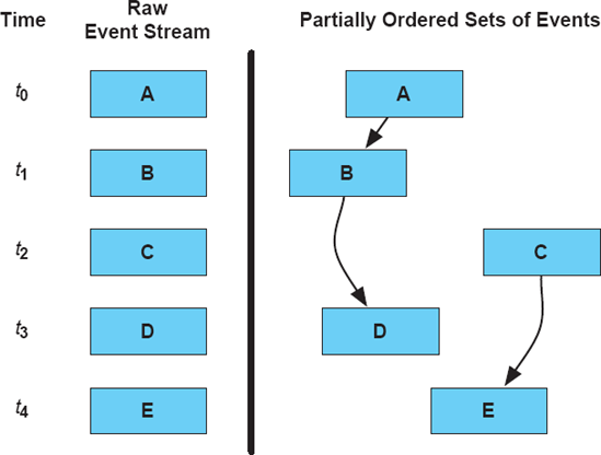
Figure 6-16 depicts this situation. The left portion of the figure shows a raw event stream over time: Components in the architecture send events A, B, C, D, and E at times t 0 through t 4, respectively. These events are temporally ordered, but not causally ordered. The right portion of the figure shows the causal ordering of the events. Here, there are two partial order sequences: one consisting of events A, B, and D, and one consisting of events C and E. This is called a partial order because not all the events are causally ordered with respect to one another. The fact that B occurred earlier in time than C is only a coincidence—an accident of the scheduler: C could just as easily have occurred before B.
Rapide focuses on capturing dynamic aspects of software architectures. Architecture specifications in Rapide are interesting because they are executable. Rapide is accompanied by a tool that allows users to execute the architecture description, in effect simulating the operation of the described system. The result is a graph of events similar to the one depicted above in Figure 6-16, showing events as nodes and causal orderings as directed edges.
Lunar Lander in Rapide. The description of Lunar Lander in Rapide looks, on the surface, similar to a Darwin description: A textual notation resembling a programming language is used to define the components and their interface operations. However, the Rapide description also includes behavioral information. This information is used, along with the application structure, to generate event graphs. Since Rapide is optimized for operating on concurrent applications where multiple threads of control interact, we will use it to evaluate a cooperative two-player version of Lunar Lander.
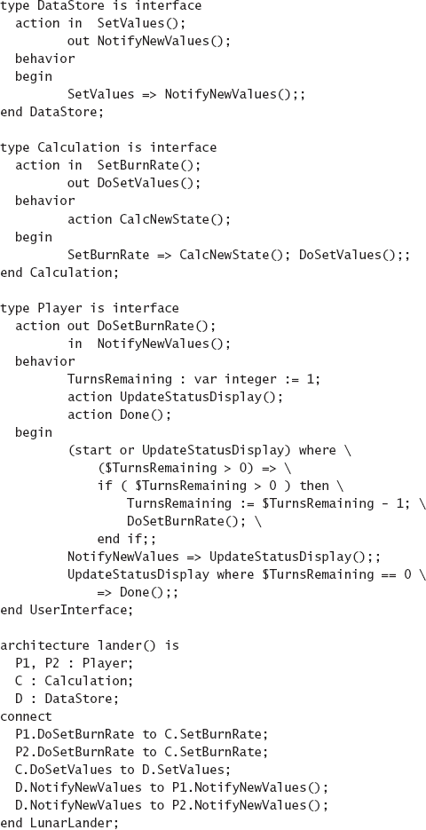
Such an architecture might be specified as shown in Figure 6-17. This specification begins by defining the types of available components primarily in terms of their interfaces. Each interface has a number of events it can receive and send out ("in" and "out" actions, respectively). Each component has a behavioral specification as well, defining how it reacts to different events. This simple example takes advantage of only a small number of Rapide language features; it has support for defining and manipulating the data that makes up the events as well. A more complex Lunar Lander specification might actually be able to simulate the entire Lunar Lander game, including data, new state calculations, and so on.
At the end of the specification, the system's structure is defined: first components that implement the various interface types, and then links between the component interfaces. This Rapide architecture is relatively straightforward: The players start off by sending an updated burn rate, making their first move of the game. Then, they wait for the display to be updated with new status before making another move. Players are limited to three moves in this system so the game does not go into an infinite loop (as there is no other end-game condition). The Calculation component waits for a SetBurnRate event. When it receives one, it will fire an internal event, CalcNewState, and then fire a DoSetValues message to the DataStore component to update the game state. When the game state is updated, the DataStore fires a NotifyNewValues event, which causes the players' displays to be updated, thus prompting them to make their next moves.
In prose, as described here, this implementation strategy might sound perfectly reasonable. But is it? Rapide's analysis and simulation capabilities can help to make that determination. If we remove the second player from the specification to create only a one-player game and run the Rapide simulator, a graph like the one in Figure 6-18 is generated. The only counterintuitive aspect of this graph is the group of "start" events that are fired initially. As one of Rapide's primary focus areas is concurrent architectures, it attempts to trigger simultaneous processing by loading the simulation with a number of "start" events at the beginning. For one player, this trace of Lunar Lander looks reasonable.

The two-player version of the graph, shown in Figure 6-19, is more complex. This is to be expected. However, by examining the causality arrows, we can see that something is not quite right. The two pathways are intertwined. Requests are getting intermingled, since there is no locking or transaction support in this design. Furthermore, we can see a fan-out of display updates at the bottom. Each user's display is getting updated twice—once for their own move and once for their partner's. For one turn, this is fine, but recall that the specification calls for the player to make a move each time the display is updated. With more players and more moves come more display updates, and each one will cause a player to try to move, compounding the effect of the interleaving. This is a non–obvious bug in the specification: All players should not reactively move after each screen update. Without Rapide's graphs, however, it is not easy to see this. This is the kind of bug that can remain undetected until it is discovered late in development during implementation or testing, when it is costly to fix.

Takeaways. Rapide addresses dynamic aspects of architecture directly, and provides tool support for the simulation of those aspects. Stakeholders can directly see how the components in a software system are intended to interact and are dependent upon each other by looking at the results of these simulations. Rapide has several significant drawbacks, however: The notation is arcane, with a steep learning curve, and it lacks support for implementing architectures in a way that is consistent with their specifications.
Wright (Allen and Garlan 1997) is focused on checking component interactions through their interfaces. Interfaces in Wright are specified using a notation derived from the Communicating Sequential Processes (CSP) formalism (Hoare 1978). Wright specifications can be translated into CSP, and then analyzed with a CSP analysis tool like FDR [Formal Systems (Europe) Ltd. 2005]. These analyses can determine, for example, if connected interfaces are compatible, and whether the system will deadlock. Additionally, Wright has the ability to specify stylistic constraints as predicates over instances.
Lunar Lander in Wright. The structural aspects of Lunar Lander, modeled in Wright, look similar to depictions we have seen earlier (for example, in a UML component diagram or Darwin). Wright's distinguishing feature is the CSP-based formal specifications of component/connector interfaces and behavior. These specifications can be specified in a notation that resembles mathematical equations, or an equivalent (if less decorative) ASCII notation. Lunar Lander, specified in Wright, might look like that in Figure 6-20.
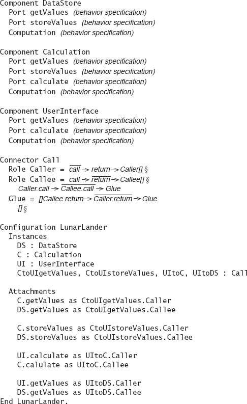
Figure 6-20. Lunar Lander modeled in Wright. Some behavioral specifications are omitted for simplicity but the Call connector is fully specified.
The main thing to notice about this specification is the detailed set of formal specifications of behavior. The CSP formalism, while semantically sound and well-documented, is somewhat arcane and has a steep learning curve that is quite different from learning, for example, a new programming language. The value of these specifications is that properties such as freedom from deadlock can be analyzed, which are difficult or impossible to detect in systems implemented in traditional programming languages.
Takeaways. Wright's formal specifications have an extremely high learning curve and cognitive overhead even for the simplest of systems. The analysis capabilities are powerful, but limited to a small set of properties (such as freedom from deadlock). However, the extensive formal modeling might be worth the effort in, for example, safety-critical systems. Support for refining architectural specifications into implementations is lacking. Like other early ADLs, Wright is not actively used and supported today.
The ADLs surveyed above are suitable for describing a wide variety of software systems in many domains and architectural styles. However, some ADLs are domain-specific or style-specific, or at least optimized for describing architectures in a particular domain or style.
Domain- and style-specific ADLs are important for several reasons. First, their scope is better tailored to stakeholder needs since they target a particular group of stakeholders, rather than software and systems developers in general. Second, they are able to leave out unnecessary details and excessively verbose constructs because there is little need for genericity. Assumptions about the domain or style can be directly encoded into the ADL's semantics instead of being repeated in every model. For example, if a particular style mandates the use of a single kind of connector between each pair of linked components, there is no need to include the notion of a connector in the ADL—the ADL's users and tool set can just assume that such connectors exist on each link implicitly.
Examples of domain- and style-specific ADLs include Koala, Weaves, and AADL. We have discussed Koala previously; it is an ADL used to model families of consumer electronics devices. Weaves is both an architectural style and an associated ADL for modeling systems composed of components that interact through streams of objects. AADL is an industrial ADL tailored for modeling embedded, real-time systems (both hardware and software).
Koala (van Ommering et al. 2000) was developed by Philips Electronics to capture the architecture of consumer electronics devices such as televisions, VCRs, and DVD players. It is, to a large extent, a domain-specific ADL—it was developed for the specific use of one company for modeling software in a single domain to address specific issues within that domain. The software systems that Koala models are composed of interconnected software components that communicate via explicit provided and required interfaces.
Semantically and syntactically, Koala is a descendant of Darwin. It uses Darwin's structural concepts of input and output ports, but expands on them through the addition of constructs to support product-line architectures. Product lines were introduced earlier, in Chapter 1. Product lines are prevalent in the consumer electronics domain, where a single product like a television may have a host of feature variations: diagonal size, audio/video inputs and outputs, and optional components such as integrated VCRs, DVD players, or both. Separately documenting the software architectures of each of these products would be redundant and error-prone, since substantially the same elements would be repeated over and over again in each product. Koala addresses this by having specific constructs in the language for explicitly defining points of variation. In this way, multiple products can be described with a single model, with differences between the products encoded as variation points.
The product-line concepts in Koala will be discussed in detail later in this book, specifically in Chapter 15. We defer the discussion of the specifics of the notation until then; interested readers should skip ahead. The evaluation rubric for Koala is presented here for completeness.
Weaves (Gorlick and Razouk 1991) is both an architectural style and an accompanying notation. Weaves is used to model systems of communicating small-grain "tool fragments" that process objects of data. Weaves can be seen as a variant of the pipe-and-filter style with three significant differences. First, Weaves tool fragments process object streams instead of pipe-and-filter's byte streams. Second, Weaves connectors are explicitly sized object queues, whereas pipe-and-filter connectors are implicit pipes. Weaves connectors serve to facilitate the transfer of both data and control among components. They receive objects from input ports, return control to the calling tool fragment, and then pass the object to tool fragments on output ports in a separate thread of control. Third, Weaves tools can have multiple inputs and outputs, whereas pipe-and-filter components have one input and one output.
Figure 6-21 shows a basic architecture expressed in the Weaves notation. The component Tool Fragment 1 outputs a stream of objects to an explicit queue connector Q1, which forks the stream and forwards the objects to both Tool Fragment 2 and Tool Fragment 3. As is obvious from this diagram, the Weaves notation is graphical and minimalist: Components are represented by shadowed boxes and queue connectors are represented by plain boxes; configurations are expressed using directed arrows connecting components and connectors.

Although the Weaves notation is minimal, it is adequate to serve as a description notation for the Weaves style. Here, additional complexity is unnecessary: Weaves' extreme simplicity and straightforwardness makes it easy to understand and interpret, and the semantic interpretations of the few elements are provided by the style itself.
Lunar Lander in Weaves. Because Weaves is both a style and an architecture description notation, expressing the Lunar Lander architecture in Weaves means something different from expressing it in a more style-neutral notation such as UML or Darwin. The actual models are nearly identical, but even though the models are similar, their meanings are not. Interpreting a Weaves model must be done through the lens of the Weaves architectural style: A component in Weaves is not the same as a component in Darwin.
The Lunar Lander system might be expressed in Weaves as shown in Figure 6-22. Here, the structure of the system itself is directly influenced by the Weaves architectural style. The components here are not communicating by means of request-response procedure calls, but instead through streams of objects. The basic flows of data are similar to the other models depicted above. One notable difference is the explicit presence of return channels for data: in Weaves, the fact that a request travels from the User Interface to the Calculation component (in the above model, through queue Q1) does not imply that a response comes back along the same path. This response's path must be explicitly specified and have its own queue (Q2 in the model).

Another interesting characteristic of the Weaves model is that it provides information about structural connections, but does not capture aspects of how those connections are used (for example, the sequences or protocols of objects that are passed through them). These details could be specified in an additional model, in natural language or a more formal notation. To elaborate the model above, we might include the following natural language specification:
The connection from User Interface to Calculation (via Q1) carries objects that include a burn rate and instruct the calculation component to calculate a new lander state. The connection from Calculation to User Interface (via Q2) indicates when the calculation is complete and also includes the termination state of the application. The connections from User Interface and Calculation to Data Store (via Q3) carry objects that either update or query the state of the lander. The connections back to User Interface and Calculation from Data Store (via Q4) carry objects that contain the lander state, and are sent out whenever the state of the lander is updated.
Takeaways. Weaves shows how binding a notation to a particular style can greatly simplify that notation. Syntactically, Weaves diagrams are extraordinarily simple (even simpler than Darwin diagrams). Unlike Darwin or other general-purpose ADLs, however, the constructs in Weaves diagrams have more specific meanings. The connection from a read port to a write port does not mean just any kind of data or control flow. Rather, it implies a very specific notion of control and data flow involving object streams passed by components running in independent threads of control. When a style is being used, tailored style-specific notations can significantly reduce the cognitive overhead of specifying and interpreting architecture models.
The Architecture Analysis and Design Language (AADL, formerly the Avionics Architecture Description Language) (Feiler, Lewis, and Vestal 2003) is an architecture description language for specifying system architectures. While its historical name indicates that its initial purpose was for modeling avionics systems, the notation itself is not specifically bound to that domain—instead, it contains useful constructs and capabilities for modeling a wide variety of embedded and real-time systems such as automotive and medical systems. It is an outgrowth of the earlier MetaH architecture description language (Binns et al. 1996) developed by Honeywell.
Like many of the other ADLs we have surveyed, AADL can describe the structure of a system as an assembly of components, though AADL has special provisions for describing both hardware and software elements, and the allocation of software components to hardware. It can describe interfaces to those components for both the flow of control and data. It can also capture non-functional aspects of components (such as timing, safety, and reliability attributes).
Syntactically, AADL is primarily a textual language, accompanied by a graphical visualization and a UML profile for capturing AADL information in different ways. The syntax of the textual language is defined using Backus-Naur Form (BNF) production rules.
The basic structural element in AADL is the component. AADL components are defined in two parts: a component type and a component implementation. A component type defines the interfaces to a component—how it will interact with the outside world. A component implementation is an instance of a particular component type. There may be many instances of the same component type. The component implementation defines the component's interior—its internal structure and construction, and so on. One additional element that affects components is a component's category. AADL defines a number of categories (or kinds) of components; these can be hardware (for example, memory, device, processor, bus), software (for example, data, subprogram, thread, thread group, process), or composite (for example, system). The category of a component prescribes what kinds of properties can be specified about a component or component type. For example, a thread may have a period and a deadline, whereas memory may have a read time, a write time, and a word size.
AADL is supported by a growing base of tools, including a set of open-source plug-ins for the Eclipse software development environment that provide editing support and import/export capabilities through the Extensible Markup Language (XML) (Bray, Paoli, and Sperberg-McQueen 1998). An additional set of plug-ins is available for analyzing various aspects of AADL specifications—for example, whether all the elements are connected appropriately, whether resource usage by the various components exceeds available resources, and whether end-to-end flow latencies exceed available time parameters.
Lunar Lander in AADL. AADL captures the hardware and software elements of a system in great detail, and relates them all to one another. As such, AADL specifications that capture all these elements can become large. Because of this, here we model only a part of the Lunar Lander system: the Calculation component and its connection to the Data Store component. In this version of Lunar Lander, the two components are connected by a physical Ethernet bus. Also, this is a real-time version of Lunar Lander—instead of operating only when the user inputs a burn rate, the calculation component periodically queries and updates the Data Store component at regular intervals. Here, perhaps the burn rate is not input from the user at the keyboard, but read at periodic intervals from a sensor connected to a burn-rate knob. This is more consistent with a sense-compute-control architectural style.
This part of the Lunar Lander system expressed in AADL might look like Figure 6-23. The first thing to note about this model is the level of detail at which the architecture is described. A component (calculation_type.calculation) runs on a physical processor (the_calculation_processor), which runs a process (calculation_process_type.one_thread), which in turn contains a single thread of control (calculation_thread), all of which can make two kinds of request- response calls through ports (request_get/response_get, request_store/response_store) over an Ethernet bus (lan_bus_type.ethernet). Each of these different modeling levels is connected through composition, mapping of ports, and so on. This level of detail emphasizes the importance of tools, such as graphical editors, for modeling this information in a more understandable fashion.

The second thing to note about this specification is the use of properties to define specific characteristics of some of the elements (for example, the calculation process runs periodically, every 20ms). In a complete system specification, these properties would be even more detailed and elaborate, and could be used by tools to answer questions about availability and timing that are critical in a real-time context.
Takeaways. AADL is a high-cost, high-value notation. The syntax and capabilities of AADL are the product of a significant amount of thought and development effort, and the kinds of analyses that can be done on AADL specifications are nontrivial. However, while users leverage the effort of the AADL developers, they also incur their own costs: AADL specifications are complex and extensive, even for small systems. This, in itself, entails significant risks and costs for users. For the specific domain in which AADL is positioned (embedded real-time systems), these costs may be worth it: These systems are often safety-critical and expensive or impossible to redeploy.
There is a natural tension between the expressiveness of general-purpose modeling languages such as UML and the semantic power of more specialized ADLs such as Wright, Weaves, and Rapide. On one hand, architects need the ability to model a wide variety of architectural concerns. On the other hand, they need semantically precise languages to reduce ambiguity and increase analyzability. Furthermore, as we have discussed, architectural concerns and product needs can vary widely from project to project. One solution is to use multiple notations, each addressing a different set of architectural concerns. However, this creates difficulty in keeping the different models consistent and establishing traceability between models. Additionally, even using multiple notations, there may be certain concerns that cannot be adequately captured in any existing notation. Extensible architecture description languages can be used to combine the flexibility of generic languages with the analyzability and precision of semantically rich languages.
Extensible ADLs generally provide a basic set of constructs for describing certain common architectural concerns (for example, components and connectors). Additionally, they also include support (through the notation and associated tools) for extending the notation's syntax to support new, user-defined constructs. In some cases, the extensions may only modify the existing base constructs. Other notations allow users to create entirely new constructs and concepts.
The basic approach to employing an extensible ADL is as follows:
Determine which concerns can be modeled using the existing (baseline) capabilities of the ADL.
For those concerns that cannot be modeled using the baseline capabilities, choose how to extend the ADL to support their modeling (or reuse an extension developed by another user).
Extend the ADL and its supporting tools as necessary to support the modeling of the unique features.
Effectively, extensible ADLs can be seen as "domain-specific ADL factories." Through extension mechanisms, users can tailor these ADLs to meet the needs of their particular domain or project. Examples of extensible ADLs include Acme, ADML, and xADL.
Acme (Garlan, Monroe, and Wile 1997) is perhaps the earliest example of an ADL that emphasized extensibility. Acme has a base set of seven constructs: components and connectors, ports and roles (roughly equivalent to this book's notion of interfaces on components and connectors, respectively), attachments (equivalent to this book's notions of links), systems (configurations of components, connectors, ports, roles, and attachments), and representations (inner architectures for components and connectors). These constructs provide a vocabulary for expressing structural design decisions about a system: basically, the system's component and connector makeup in a box-and-arrow form.
Extensibility in Acme is derived through the use of properties. Properties are decorations that can be applied to any of the basic seven kinds of elements. Properties are optionally typed name-value pairs. Names are simple strings, and the values should conform to the property's type, if it has one. Acme includes a number of simple property types (integers, Booleans, and so on), as well as the ability to define custom types. Either way, from Acme's point of view, properties and their values are uninterpreted. It is up to user-written tools to parse these properties (and any internal structure they contain) and do something useful with the contents (for example, provide analysis or visualization capabilities).
Originally, it was anticipated that Acme's primary use would be as an architecture interchange language, rather than an ADL or even an extensible ADL. That is, developers of other ADLs such as Wright and Rapide would develop translators that mapped their languages to and from Acme: In this way, models could be interchanged among many different tools for, say, analysis. This strategy was never applied on a wide scale, however, possibly because of substantial semantic differences and conflicts among target ADLs.
Lunar Lander in Acme. The basic specification of Lunar Lander in Acme is similar to models shown above. It is largely structural and includes components, connectors, ports, roles, and attachments. Lunar Lander, specified in Acme, might look like Figure 6-24. One interesting thing to note about this model is its verbosity, especially compared to some earlier models. This is a result of two key decisions made by the Acme designers. First, the Acme language is domain-neutral: little can be abbreviated out of the model, because the underlying Acme semantics make few assumptions that allow information to be conveyed implicitly. Second, the Acme designers intended Acme models to be edited through graphical tools and developed an environment called AcmeStudio that allows users to design Acme structures using a GUI interface rather than writing the complete textual description of the model in a text editor. This limits the amount of additional effort Acme users must expend to deal with Acme's verbosity.

A second thing to notice about the model is the use of properties. In this basic model, only one kind of property is used: Each procedure call connector is annotated with a property indicating whether or not the operation has a return value. This might be useful to designers looking to make a partially asynchronous version of Lunar Lander: Calls without return values may be able to return control to the caller without waiting for their completion. Acme's type system is used to declare a connector and a property type, such that regularity can be imposed over connectors and properties that are similar (for example, all connectors in the above Lunar Lander model are of the same type: CallType). Types in Acme work in a manner similar to stereotypes in a UML profile: They allow the user to set expectations on instance elements that can be checked later.
Compared to the other Lunar Lander models above, this basic Acme model is not very innovative. However, additional properties can add detail to this model in a number of ways, depending on the stakeholder's needs. For example, we might say more about how the DataStore component stores its data, as shown in Figure 6-25. This extended description of the component is intended to indicate that the DataStore component should store its data in a non-replicated table called "LanderTable" in a relational database. However, the fact that the model uses these particular property names and values is not a standard: Tools and stakeholders must be informed about which properties to expect and how to process their values.
Takeaways. Notwithstanding the relative failure of architectural interchange, the notion that extensibility should be a primary concern in ADL development is a good one—it is an explicit recognition that there cannot be a one-size-fits-all ADL. Property-based decorations as an extensibility mechanism provide a degree of flexibility, but the breadth of architectural concerns that stakeholders want to capture requires the ability to define new first-class constructs.
The Architecture Description Markup Language (ADML) (Spencer 2000) is an XML-based architecture description language whose syntax is derived from Acme. It was originally developed by the MicroElectronics and Computer Technology Consortium (MCC) and is maintained as a standard by the Open Group. Semantically, the two are nearly identical, with ADML's primary addition being support for meta-properties. In ADML, meta-properties provide a mechanism by which users can specify the properties (and property types) that should be present on particular elements.

Using the Extensible Markup Language (XML) as the basis for an architecture modeling notation confers several benefits. XML provides a standard framework for expressing the syntax of notations. It is well suited to describing hierarchical organizations of concepts, and internal references can be used to create "pointers" from one element to another. A significant practical benefit of the use of XML is the panoply of off-the-shelf commercial and open-source tools that are available for parsing, manipulating, and visualizing XML documents. Using these tools can significantly reduce the amount of time and effort needed to construct architecture-centric tools such as analyzers, editors, and so on.
XML can be used to create languages with extensible syntax. However, early XML standards provided limited support for this. ADML's syntax is defined using an XML document type definition (DTD), one of the earliest XML meta-languages, which uses production rules to define syntax. XML DTDs have been used to create extensible languages, but the mechanisms are somewhat cumbersome. Instead, ADML provides its extensibility through the same mechanism as Acme—name-value pair properties applied to a core set of elements.
Lunar Lander in ADML. Because ADML is so similar to Acme, we will not provide a complete ADML description for the Lunar Lander application. The description of the Data Store component in ADML might look like Figure 6-26. Although the semantic content of this ADML snippet is virtually identical to its Acme counterpart, the use of XML as a standard syntactic framework opens this specification up to a much wider array of tools such as parsers and editors that would not necessarily be otherwise available (or as ubiquitous). One obvious drawback is that by employing XML, the already verbose Acme description becomes even denser. This reflects the overall attitude of XML in general—computing resources and data storage have become inexpensive and plentiful, and editing tools have become ubiquitous. Conservation of data bytes is no longer a driving force in language design.
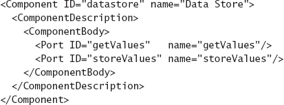
Takeaways. XML provides many extrinsic benefits for architecture modeling, and nearly all architecture description notations still under development at least have the option to import from and export to XML. ADML does not take advantage of XML's own extensibility mechanisms, and instead provides extensibility by simply encoding Acme's name-value pair properties into XML.
xADL (Dashofy, van der Hoek, and Taylor 2005) is an attempt to provide a platform upon which common modeling features can be reused from domain to domain and new features can be created and added to the language as first-class entities (not just extensions to other entities as with Acme and ADML). Like ADML, xADL is an XML-based language. That is, every xADL model is a well-formed and valid XML document. The main difference is that unlike ADML, xADL fully leverages XML's extensibility mechanisms for its language extensions.
The syntax of the xADL language is defined in a set of XML schemas. XML schemas are similar to DTDs in that they provide a format in which to define the syntax of a language. Whereas DTDs define document syntax through production rules, XML schemas define syntax through a set of data types, similar to the way data structures are defined in an object-oriented programming language. Like classes in an object-oriented programming language, XML schema data types can be extended through inheritance. Derived data types can be declared in separate schemas. Through this mechanism, data types declared in one schema can be extended in a different schema to add new modeling features.
Syntactically, the xADL language is the composition of all the xADL schemas. Each xADL schema adds a set of features to the language. The constructs in each schema may be new top-level constructs or they may be extensions of constructs in other schemas. Breaking up the feature set in this way has several advantages. First, it allows for incremental adoption —users can use as few or as many features as makes sense for their domain. Second, it allows for divergent extension —users can extend the language in novel, even contradictory ways to tailor the language for their own purposes. Third, it allows for feature reuse —because feature sets are defined in XML schema modules, schemas can be shared among projects that need common features without each group having to develop its own (probably incompatible) representations for common concepts.
From time to time, new schemas are added to xADL as they are developed, by both its creators and outside contributors. Current xADL schemas are shown in the box.
Because xADL can be extended with unforeseen constructs and structures in nearly arbitrary ways, it induces challenges that do not exist in languages with unchanging syntaxes and semantics (most of the other ADLs we have covered). Specifically, parsers, editors, analyzers, and other tools must be developed to cope with a notation whose syntax may change from project to project.
xADL addresses these challenges with an associated set of tools that make it easier for users to implement their own tools (for example, analyzers, editors) that can handle the language's extensible syntax. These include the following.
The xADL Data Binding Library. A data binding library is a software library that provides an API for parsing, reading, writing, and serializing (writing back out to disk or other storage) documents in a particular language. In xADL's case, the data binding library consists of a set of Java classes that correspond to xADL data types. A program can query and manipulate instances of these classes to explore and change an xADL document. Although xADL documents can also be read, written, and manipulated with any XML-aware tool, the data binding library provides a much simpler interface and is the basis for most of the other xADL tools developed to date.
Apigen. The data binding library would be of limited use if it had to be manually rewritten each time schemas were added to xADL. Apigen (Dashofy 2001) is xADL's data binding library generator: Given a set of XML schemas, it can generate the complete data binding library with support for those schemas. If a user changes or adds a schema, a new data binding library can be generated by rerunning Apigen; this library will contain classes for querying and manipulating the new or changed data types defined in the user's schema.
Lunar Lander in xADL. For basic structural specifications, xADL has a great deal in common with Acme and ADML. The basic structure of the Lunar Lander application, expressed in xADL's xADLite textual visualization might look like Figure 6-27. Like Darwin and other ADLs, xADL also has an associated graphical visualization. This visualization is provided by an editor called Archipelago, which is part of the xADL tool set.
The model of Lunar Lander rendered by Archipelago is shown in Figure 6-28. As with Acme, the key notational contribution of xADL lies in its extensibility. xADL's extensibility goes beyond adding properties to the core constructs. In fact, xADL has no fundamental separation between core concepts and extensions. xADL allows the addition of completely new syntactic elements in addition to structured extensions to existing elements.
Reusing the example of the improved data source component specification above for Acme, let's look at how more detail about the data store component might be added to xADL (and the xADL specification of Lunar Lander). The XML schema specification for a "plain" xADL component (as used above) is shown in Figure 6-29. Simply put, this specification says that a component has the following.


By adding another schema, we can create an extended form of a component that can be used to capture more information about where the component will store data. An example extension is shown in Figure 6-30. This extension to the xADL language adds several new capabilities. First, it defines a new abstract data type called Database. This is like declaring an abstract class in an object-oriented programming language: It indicates we are going to define many different subtypes of Database that will be substitutable whenever a Database is needed. Then, it defines two concrete subtypes of Database: RelationalDatabase and FileDatabase. These have different characteristics: a RelationalDatabase has a table name and a number of replicas, while a FileDatabase has a file name and an optional host name on which the file resides.
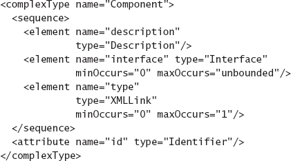

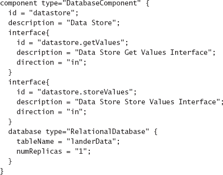
Finally, it defines an extension to the plain xADL Component datatype. A DatabaseComponent has everything that a component does, plus a Database element. Because both RelationalDatabase and FileDatabase are Databases, either one can be used here (as well as other user-defined database types in other schemas).
We can now extend the original xADL description of the Data Store component in the Lunar Lander application, as shown in Figure 6-31. Using these mechanisms, stakeholders can define their modeling needs very precisely. When the new "DatabaseComponent" schema is ready, Apigen can generate a new data binding library that supports the new constructs. Furthermore, sharing of schemas is possible (and encouraged)—the above "DatabaseComponent" schema could be reused from project to project, as well as any tools that provide advanced processing (editing, analysis, and so on) on elements from this schema.
Takeaways. While xADL's basic modeling capabilities rival those of other ADLs we have covered, xADL's primary contribution is in its extensibility. xADL heavily leverages XML's (and XML Schema's) extensibility mechanisms to create a domain-specific ADL factory, where domain-specific ADLs (and supporting tools) can be created at a much lower cost than developing them from scratch. xADL is supported by a variety of visualization, analysis, and utility tools in the ArchStudio environment. These various tools will be discussed throughout the remainder of the book.
In this chapter, we have shown how various notations can express a simple application like Lunar Lander. The Lunar Lander architecture has certain properties that simplify modeling: It has a finite number of well-known components that run on a single host. Even large distributed systems can be modeled in similar ways, although the effort required to model these systems increases with their size. However, certain applications (especially Internet-scale applications) cannot be modeled using these same techniques. For example, it would be virtually impossible to model the Web, or Gnutella (Kan, 2001) using some of the modeling techniques above. These are gigantic and diverse applications. The configuration of components and connectors on the Internet is constantly changing. In fact, they are so big and so volatile that it is impossible to know the configuration of components and connectors at any given time. Thus, it is not possible to generate a model of these systems in the traditional components-connectors-and-configurations sense. There are far too many components, and the structure of the application is changing too fast.
Modeling applications with this kind of complexity is possible, using some of the techniques we have already discussed. All of them involve abstracting away aspects of the complexity to get to a point where modeling is feasible but still useful. This is the essence of modeling. Strategies to consider in this case include the following.
Model limited aspects of the architecture: Many times, the largest or most complex part of an architecture is limited to one particular perspective. For example, trying to model the structure of the Web would be impossible. However, use cases or interaction patterns are more limited, and might be modeled more easily.
Model an instance: The first thing to consider is whether a complete model of such a system is actually needed. In general, nobody needs to model the entire Web or Gnutella P2P network at any given time. Instead, consider modeling only the portion of the system that is relevant, which will almost certainly be a (relatively) small subset of the total system.
Exploit regularity: Often, extremely large systems have low heterogeneity. Large portions of the system will, for modeling purposes, look almost exactly like other portions of the system. These portions can be modeled once and repeated automatically, or decorated with a property indicating how many of them there are. Recall Darwin's ability to specify multiple homogenous clients using a "for loop" construct.
Model the style: As discussed earlier in the book, the Web is based on the REST architectural style. Instead of modeling the Web as an application, consider modeling the REST style instead. We have discussed several notations that allow modeling of different kinds of architectural style constraints; these can be used for this purpose.
Model the protocol: The "contract" that large distributed systems adhere to is often captured in the interaction protocol between components. For example, the Web is, in large measure, characterized by adherence to the HTTP protocol (Fielding et al. 1999). A number of the notations discussed in this chapter can be used to model protocol details, such as natural language (albeit informally) and Wright.
In this chapter, we have introduced architecture modeling and identified many of the issues that occur in the modeling process. We have also introduced and provided examples of many architecture description notations.
It is impossible to provide deep coverage of the variety of architecture description notations in this text—indeed, books, theses, and academic papers abound discussing each notation in great detail. Instead, we have attempted to highlight the distinguishing aspects of each notation. We encourage interested readers to leverage the Web and the resources indicated at the end of the chapter to investigate these ADLs more thoroughly from primary sources.
The goal of this chapter is to give readers a sense of the breadth of the modeling activity, as well as the notations, tools, and techniques that are available to support it. What should be obvious is that no single notation—even an extensible notation—is sufficient to capture all the aspects of architecture that will be important for a complex project. Stakeholders must make informed choices of techniques, based on the needs of the project at hand. The following table recaps the modeling approaches we have discussed in this chapter and attempts to group them into categories that share characteristics. Note that some approaches fall in more than one category. One example is Darwin. It is grouped with the syntactically rigorous ADLs such as UML and OMT because of its usefulness as a straightforward way of rigorously capturing and communicating architectural structure. It is also in the formal category because of its formal foundations in the pi calculus, although these formal foundations are rarely exploited.
Ideally, stakeholders and architects would simply be able to select a mature notation that would cover their modeling and analysis needs. However, the reality is that there are not enough mature notations currently available to make this possible. Even if one were prepared to use several notations simultaneously (and deal with the costs of managing consistency among them), there will likely still be gaps between what can be modeled and what stakeholders need. This means that architects will not only have to invest in modeling, but invest in developing the technologies they use to model. Modeling would be substantially more effective if a portion of the total design budget of a system were devoted to enhancing the fundamental technologies used to do the design. Nevertheless, selecting and using at least one architecture modeling notation—preferably an extensible notation—is worlds better than not doing modeling at all, and significantly better than using a semantically impoverished notation such as PowerPoint or UML.
Category | Category Characteristics | Examples |
|---|---|---|
Informal/Free-form | High expressiveness, ambiguity, lack of rigor, no formal semantics | Natural language, informal graphical diagrams. |
Syntactically rigorous | Rigorous syntax but few semantics, primarily useful for communication. | UML, OMT, Darwin. |
Formal | Rigorous syntax and underlying formal semantics, automated analyses possible, steeper learning curves. | Darwin, Rapide, Wright. |
Domain- or style-specific | Optimization for a particular domain or style, has strong mapping to domain or style-specific concepts. | Weaves, Koala, AADL. |
Extensible | Support for a core set of constructs and the ability for users to define their own. | ACME, ADML, xADL, UML. |
Selecting notations for use on a project is a subtle and complex activity. This chapter focused on what aspects of architecture are modeled by different notations, and how those notations model those aspects. These are only two factors in selecting a notation. Other important questions must also be answered: What kinds of visualizations are available with the notation? What kinds of analyses can be performed on models in the notation? How can models in this notation be tied to other life cycle phases? All these aspects of designing will be addressed in subsequent chapters. The next chapter focuses specifically on visualizations, where we separate the abstract concept of a notation (a way of organizing the information in design decisions) from the different ways that the information can be interacted with and depicted.
What is an architectural model? What is its relationship to an architecture? To design decisions?
What is the difference between accuracy and precision in general? In the context of architectural modeling?
What is the difference between a view and a viewpoint?
Enumerate some common architectural viewpoints. What kind of data is captured in each viewpoint?
What does it mean for two views to be consistent? What kinds of inconsistencies can arise in multiview models?
What kinds of dimensions can you use to evaluate a modeling notation?
Enumerate some modeling notations and describe what kinds of design decisions they can capture.
What are the distinctive modeling features of Darwin? Of Wright? Of Rapide? Of Weaves?
What are the advantages of using an extensible ADL? What are some disadvantages?
What are some modeling strategies that can be used when a system is too big or complex to create a complete architectural model?
Research in more depth the syntax and semantics of one of the ADLs in this chapter and model a system of your choosing in that ADL.
Download a tool set for one of the modeling notations described in this chapter and model a simple application like Lunar Lander in that tool set. Reflect on your experiences and the strengths and weaknesses of the tool set.
Map the syntax of an earlier ADL (for example, Darwin, Wright, Rapide) to an extensible ADL. What services are provided by the extensible ADL? What extensions are needed to fill in the gaps? Define these extensions using the mechanisms provided by the extensible ADL.
Choose a software-intensive system and research how this system's developers employed modeling. What kind of models were created and how are they used? How are they maintained?
Research how other disciplines (for example, computer engineering or building architecture) approach the modeling task. What do they model? What notations do they use? Do similar issues (such as view consistency) occur in those disciplines? How are they handled there?
Do you agree that UML is an architecture description language? Argue for or against.
Model a simple system like Lunar Lander in two different notations, or in two different viewpoints in the same notation (for example, two UML diagrams). Ensure that the models are consistent, and explain why and how you established that consistency.
Choose a concern or view not supported by one of the extensible ADLs and develop an extension to support that concern or view.
The chapter opens with an insight about modeling from Maier and Rechtin's The Art of Systems Architecting (Maier and Rechtin 2000). While not solely about modeling, this book addresses architecture from the perspective of a systems engineer, which is, in general, broader and less concrete than the perspective of a software engineer. As with much of the content of this book, Maier and Rechtin's advice is often equally applicable to both systems and software development.
The bulk of this chapter introduces and surveys a broad variety of modeling notations. Although we have endeavored to distill each notation down to its essence and comment on the aspects of the notations that we believe are distinctive, the few pages dedicated to each notation often cannot adequately capture its scope and subtlety. Interested readers should investigate source documents and specifications related to these notations for more in-depth treatments. Tools for working with unconstrained graphical notations such as PowerPoint (Microsoft Corporation 2007), Visio (Microsoft Corporation 2007), and OmniGraffle (The Omni Group 2007) are widely available. Many books have been written about UML, but the canonical reference is from the developers themselves (Booch, Rumbaugh, and Jacobson 2005). Medvidović and Taylor surveyed early ADLs (Medvidović, and Taylor 2000). These included Darwin (Magee et al., 1995), Wright (Allen and Garlan, 1997) [treated even more extensively in Allen's Ph.D. thesis (Allen 1997)], and Rapide (Luckham et al. 1995), which inspired Luckham et al.'s later work in complex event processing (Luckham 2002). UML's takeover of modeling most of the generic architectural views resulted in second-generation ADLs like Koala (van Ommering et al. 2000) and AADL (Feiler, Lewis, and Vestal 2003) [itself based on an earlier ADL, MetaH (Binns et al. 1996)], that addressed more domain-specific concerns. An exciting direction in ADL development remains the creation and growth of extensible ADLs, from early examples like Acme (Garlan, Monroe, and Wile 1997) and ADML (Spencer 2000) to later, more flexible examples such as xADL 2.0 (Dashofy, van der Hoek, and Taylor 2005).
Clements et al. (2002) have dedicated an entire book to the issue of documenting software architectures, which focuses primarily on modeling. Their book takes a viewpoint-centric approach, surveying a wide variety of viewpoints and providing guidance as to what should be captured in each. Their book also surveys salient notations and standards.
[8] In the early days of computing, some programming language designers believed that programming languages could be improved by making them more like natural language with added syntactic rigor. Thus, languages like COBOL included statements such as, "MULTIPLY X BY 5 GIVING Z," instead of the terser "z = × * 5." Such techniques have fallen out of favor, as they only served to make programs more verbose.
[9] This diagram uses the UML 2 ball-and-socket icons to represent provided and required interfaces, respectively. In earlier versions of UML 2, the socket and ball could be directly graphically joined (without an intervening dependency arrow) to indicate connection, but this diagrammatic style has been deprecated by the UML committee except in composite structure diagrams.