
Designing and implementing the functionality and managing the data of modern large, complex, distributed, multilingual software systems is undoubtedly very difficult. As discussed in the preceding chapters, early software architectural models of system components, their key services, their abstract behaviors, and their nonfunctional properties are indispensable in this endeavor. However, experience has shown time and again that making architectural design decisions that pertain to integrating those components effectively and ensuring the components' proper interaction in a system is just as important. Moreover, arriving at such design decisions can be even more challenging than those restricted to the development of functionality. The particular importance in modern systems of mechanisms for assembling functional components and supporting their interaction, that is, software connectors, mandates that they be treated and studied separately. We will do just that in this chapter, and will return to this subject repeatedly throughout the remainder of the book.
Simply put, software connectors perform transfer of control and data among components. Connectors can also provide services, such as persistence, invocation, messaging, and transactions, that are largely independent of the interacting components' functionalities. These services are usually considered to be "facilities components" in widely used middleware standards such as CORBA, DCOM, and RMI. However, recognizing these facilities as connectors helps to clarify an architecture and keep the components' focus on application- and domain-specific concerns. Treating these services as connectors rather than components can also foster their reuse across applications and domains. Perhaps most importantly, connectors allow architects and engineers to compose heterogeneous functionality, developed at different times, in different locations, by different organizations. As such, connectors can be thought of quite appropriately as the guards at the gate of separation of concerns.
A common misconception about software connectors is that they are just calls between two components, in the manner of, say, a Java method invocation. A slightly more advanced view, inspired by middleware-based system development, is that component interactions take place via message passing and remote procedure calls (RPC). While it is frequently the case that two components will eventually be implemented to communicate using, say, a Java method call, it is important to realize that as a software system's architect you are not restricted to assuming and relying on only such primitive interaction mechanisms.
Traditional software engineering approaches embrace a rather narrow view of connectors that is unlikely to be successfully applicable across all development situations. This problem is further exacerbated by the increased emphasis on development using large, off-the-shelf components originating from multiple sources. As components become more complex and heterogeneous, the interactions among them become more critical determinants of system properties. Experience has shown that integrating components with mismatched assumptions about their environment is hard to do and can lead to many problems. It is the task of connectors to mitigate such mismatches.
An architect has a wide range of connector options that are applicable, and often tailorable, to different development needs and scenarios. For example, an architect can choose to use a connector that distributes a service request to specifically named recipient components or a connector that broadcasts a notification of a locally occurring event to any (unnamed and even unknown) component that may be interested and listening. The connector may require the sender component to suspend its processing until an acknowledgment of its request is received, or it may allow the sender component to continue with its processing; the connector can route each request in the order it received it, or it can try to order, filter out, or combine requests according to some prespecified rule; and so on. Therefore, a very important dimension of a software architect's job is to:
Understand the component interaction needs.
Carefully identify all of the relevant attributes of that interaction.
Select the candidate connectors.
Assess any trade-offs associated with each candidate.
Analyze the key properties of the resulting component-connector assemblies.
The goal of this chapter is to provide insights, guidelines, and specific techniques to support accomplishment of these tasks. The remainder of the chapter will introduce:
The different roles connectors play in a software system.
Different connector types a software architect has at his or her disposal and the roles each type can fulfill.
A panoply of variation points for each connector type.
A set of general hints and guidelines about a connector's applicability, strengths, and drawbacks.
Throughout the chapter, we will provide examples of specific software connectors to illustrate the discussion. The reader will probably be familiar with many of these connectors, although sometimes under a different name. The chapter starts off with a simple concrete example, to set the stage for the subsequent discussion.
This chapter provides a detailed treatment of connectors. The type and amount of information provided is necessary for their thorough study. At the same time, some of the content may be unsuitable for an inexperienced reader. We recommend that everyone read at least Sections 5.1 through 5.4 as well as Sections 5.7 through 5.10. Section 5.5 contains a set of examples from the domain of large-scale data distribution systems, which can be followed by most readers, but their full appreciation may require prior experience with these types of systems. Section 5.6 is appropriate for all readers, but is targeted, in particular, at the experienced professionals and readers interested in practical guidelines for constructing advanced connectors.
Outline of Chapter 5
5 Connectors
5.1 Connectors in Action: A Motivating Example
5.2 Connector Foundations
5.3 Connector Roles
5.4 Connector Types and Their Variation Dimensions
5.4.1 Procedure Call
5.4.2 Event
5.4.3 Data Access
5.4.4 Linkage
5.4.5 Stream
5.4.6 Arbitrator
5.4.7 Adaptor
5.4.8 Distributor
5.5 Example Connectors
5.5.1 Event-Based Data Distribution Connectors
5.5.2 Grid-Based Data Distribution Connectors
5.5.3 Client-Server-Based Data Distribution Connectors
5.5.4 P2P-Based Data Distribution Connectors
5.6 Using the Connector Framework
5.6.1 Selecting Appropriate Connectors
5.6.2 Detecting Mismatches
5.7 End Matter
5.8 Review Questions
5.9 Exercises
5.10 Further Reading
One useful property of connectors is that they are for the most part application-independent architectural elements. That means that they enable us to understand a lot about how a software system accomplishes its tasks without necessarily having to know exactly what the system does. In other words, connectors directly support two key principles of software engineering: abstraction and separation of concerns. Explicitly focusing on connectors also enables development and use of a specific vocabulary of software interaction. In turn, agreeing on appropriate terminology allows us to communicate easily and reason precisely about a number of software system properties that derive from the system components' interactions. To illustrate this, we use a very simple example involving two different types of connectors. We intentionally use the terminology associated with those connectors without defining it, to draw attention to this new "language." The appropriate definitions and explanations will be given in the subsequent sections. Nonetheless, you will probably find that you are familiar with some, if not most, of this terminology.

Figure 5-1. A simple pipe-and-filter architecture consisting of two filters, A and B, communicating via untyped data streams through the unidirectional pipe connector P.
Different views of a software connector are useful for different tasks. In order to model a system and communicate its properties, a high-level view is suitable. For example, an architect may make the following concise, but meaningful statement about the configuration shown in Figure 5-1: "Components A and B communicate via a Unix pipe." That statement may be accompanied by a formal specification of the pipe's overall behavior. However, such a high-level description does not help us understand all the properties of the pipe, how it can be adapted, or under what conditions it can be replaced with another type of connector. A more detailed, lower-level view is needed to accomplish that.
In particular, the pipe in Figure 5-1 allows interaction via unformatted streams of data. It is a simple connector: It consists of a single interaction channel, or duct, and facilitates only unidirectional data transfer. Thus, the cardinality of the pipe is a single sender and a single receiver. You will recall from the preceding chapters that a pipe allows components (that is, filters) A and B to exhibit very low coupling: The components do not possess any knowledge about one another. For example, A's task is only to successfully hand off its data to the pipe; the actual recipient (if any) is unimportant to A. In turn, the particular pipe depicted in Figure 5-1 does not buffer the data. It attempts to deliver the data at most once; if the recipient is unable to receive the data for some reason, the data will be lost.
Let us now assume that we need to alter the manner in which A and B interact, such that B can also send information (for example, acknowledgement of data receipt) back to A. Furthermore, we want to ensure the delivery of data: If the recipient is not available, the pipe retries to send until the data is successfully transferred. Both these modifications can be potentially accommodated by pipes. The first modification would require introducing another pipe from B to A, and the second, data buffering in a pipe. Addition of any other components into the system would require further addition and/or replacement of pipes. The penalty we would pay is that these modifications may require substantial system downtime. Pipes can, therefore, accommodate these new requirements, even though constantly adding and replacing them may not be the most effective solution.

Figure 5-2. An event-based architecture consisting of two components, A and B, communicating via typed discrete data packets (events) through the event bus connector E. The connector allows on-the-fly system modifications, such as adding a new component C.
If, however, we want to change the nature of the data from an unformatted byte stream to discrete, typed packets that can be processed more efficiently by the interacting components, pipes will not suffice. In such a case, an event bus connector will be a more suitable alternative. Although clearly different types of connectors, pipes and event buses exhibit a number of similar properties, such as loose component coupling, asynchronous communication, and possible data buffering. At the same time, event buses are better suited to support system adaptation: an event bus connector is capable of establishing ducts between interacting components on the fly; its cardinality is a single event sender (similarly to the pipe), but multiple observers. Thus, in principle, event buses allow components to be added or removed, and to subscribe to receive certain events, at any time during a system's execution. Figure 5-2 abstractly depicts the use of an event bus to accommodate the above changes.
The underlying, elementary building blocks of every connector are the primitives for managing the flow of control (that is, changing the processor program counter) and flow of data (that is, performing memory access) in a system. These primitives give enough conceptual power to build sophisticated and complex connectors. In addition to these primitives, every connector maintains one or more channels, also referred to as ducts, which are used to link the interacting components and support the flow of data and control between them. A duct is necessary for realizing a connector, but by itself, it does not provide any additional interaction services. Very simple connectors, such as module linkers, provide their service simply by forming ducts between components. Other connectors augment ducts with some combination of data and control flow to provide richer interaction services. Very complex connectors can also have an internal architecture that includes computation and information storage. For example, a load balancing connector would execute an algorithm for switching incoming traffic among a set of components based on the knowledge about the current and past load state of components.

Simple connectors are typically implemented in programming languages. On the other hand, composite connectors are achieved through composition of several connectors (and possibly components), and usually are provided as libraries and frameworks. Simple connectors only provide one type of interaction service, whereas composite connectors may combine many kinds of interactions. Complex connectors can help overcome the limitations of modern programming languages. However, when creating such connectors it is important to be able to reason about their underlying, low-level interaction mechanisms, identify the appropriate design choices, and detect potential mismatches among the interaction mechanisms used to compose a connector.
To this end, we will use the connector classification framework shown in Figure 5-3: Each connector is identified by its primary service category and further refined based on the choices made to realize these services. The characteristics most commonly observed among connectors are positioned toward the top of the framework, whereas the variations are located in the lower layers. The framework comprises service categories, connector types, dimensions (and possibly their subdimensions), and values for the dimensions. A service category represents the broad interaction role the connector fulfills. Connector types discriminate among connectors based on the way in which the interaction services are realized. The architecturally relevant details of each connector type are captured through dimensions, and, possibly, further subdimensions. Finally, the lowest layer in the framework is formed by the set of values a dimension (or subdimension) can take. Note that a particular connector instance (that is, species) can take a number of values from different types. In other words, this classification does not result in a strict hierarchy, but rather in a directed acyclic graph.
The remainder of this chapter describes in more detail the classification framework and a comprehensive taxonomy that can be used as the foundation for studying, classifying, and using software connectors.
A software connector can provide one or more of four general classes of services: communication, coordination, conversion, and facilitation. Put another way, a connector can play one or more of these four roles. Since these services, or roles, fully describe the range of possible software component interactions, the topmost layer in our classification framework from Figure 5-3 is the service category. Discussions and simple examples of the four service classes follow.
Connectors providing communication services support transmission of data among components. Data transfer services are a primary building block of component interaction. Components routinely pass messages, exchange data to be processed, and communicate results of computations.
Connectors providing coordination services support transfer of control among components. Components interact by passing the thread of execution to each other. Function calls and method invocations are examples of coordination connectors. Higher-order connectors, such as signals and load balancing connectors, provide richer, more complex interactions built around coordination services.
Connectors providing conversion services transform the interaction required by one component to that provided by another. Enabling heterogeneous components to interact with each other is not a trivial task. Interaction mismatches are a major hindrance in composing large systems. The mismatches are caused by incompatible assumptions made by components about the type, number, frequency, and order of interactions in which they are to engage with other components. Conversion services allow components that have not been specifically tailored for each other to establish and conduct interactions. Conversion of data formats and wrappers for legacy components are examples of connectors providing this interaction service.
Connectors providing facilitation services mediate and streamline component interaction. Even when components have been designed to interoperate with each other, there may be a need to provide mechanisms for further facilitating and optimizing their interactions. Mechanisms such as load balancing, scheduling services, and concurrency control may be required to meet certain nonfunctional system requirements and to reduce interdependencies among interacting components.
Every connector provides services that belong to at least one of these four categories. Commonly though, connectors provide multiple services in order to satisfy the need for a richer set of interaction capabilities. For example, procedure call, one of the most widely used software connector types, provides both communication and coordination services.
Interaction services broadly categorize connectors, but leave many details unexplained. This level of abstraction cannot help us build new connectors, and it cannot be used to model and analyze them in an architecture. Hence, we further classify connectors into eight different types, based on the way in which they realize interaction services:
Procedure call
Event
Data access
Linkage
Stream
Arbitrator
Adaptor
Distributor
Connector types are the level at which architects typically consider interactions when modeling systems.
Simple connectors can be modeled at the level of connector types; their details can often be left to low-level design and implementation. On the other hand, more complex connectors often require that many of their details b e decided at the architectural level so that the impact of these decisions can be studied early and on a systemwide scale. Those details represent variations in connector instances and are treated as connector dimensions in the below classification. In turn, each dimension has a set of possible values. The selection of a single value from each dimension results in a concrete connector species. Instantiating dimensions of a single connector type forms simple connectors; using dimensions from different connector types leads to a composite (higher-order) connector species.
The remainder of this section will describe the key characteristics of each connector type as well as their variation points. Additionally, we will highlight the interaction role(s) played by each connector type. The discussion draws extensively from the connector taxonomy set forth by Nikunj Mehta, Nenad Medvidović, and Sandeep Phadke (Mehta, Medvidović, and Phadke 2000). It should be noted that the characteristics of different connectors introduced are meant to cover the entire space of connectors. However, it is possible that an individual connector of a given type may not possess each of that type's dimensions. The detailed connector characteristics presented below can be thought of as design templates that software architects can use to select the exact connectors needed in a given system. As will be discussed further in Chapter 6, several software architecture modeling notations support different variations of this selection process.
Procedure call connectors model the flow of control among components through various invocation techniques. They are thus coordination connectors. Additionally, procedure calls perform transfer of data among the interacting components through the use of parameters and return values. They are thus also communication connectors. These connectors are among the most widely used and best understood connectors, and have been likened to the assembly language of software interaction. Examples of procedure call connectors include object-oriented methods, fork and exec in Unix-like environments, call-back invocation in event-based systems, and operating system calls. Procedure calls are frequently used as the basis for composite connectors, such as remote procedure calls or RPC, which also perform facilitation services.
The space of options available to a software engineer for constructing procedure call connectors is shown in Figure 5-4. Note that the values for certain dimensions and subdimensions are not shown: multiple versus single entry point, as well as fan in and fan out cardinality. These are numerical subdimensions that either take an obvious value (1 in the case of single entry point) or can take many values (in the case of the remaining three subdimensions). They are hence elided for simplicity; we likewise omit the values of all such dimensions and subdimensions in the case of the other seven connector types.
A typical programming language-level procedure call connector takes on a specific set of values from the choices depicted in the figure. For example, as most Java users will readily know, a procedure (that is, method) call provides the data transfer of its parameters by reference; it may have a return value unless the invoked method is declared as a void; it will have a single entry point, at the start of the invoked method; it will be a result of explicit invocation; its synchronicity will be blocking; its fan in and fan Out cardinality will both be 1—that is, a Java method call always has a single source and a single destination; finally, its accessibility may be public or private.

At this point, the reader is not necessarily expected to understand all of this connector type's various dimensions, subdimensions, and values, or all of the variation points of the remaining seven connector types discussed below and depicted in Figure 5-5 through Figure 5-11. One objective of this chapter is to sensitize the reader to the richness and potential complexity of the space of software connectors. The remainder of the chapter will continue to highlight only the representative or particularly interesting facets of each connector type.
David Rosenblum and Alexander Wolf define an event as the instantaneous effect of the (normal or abnormal) termination of the invocation of an operation on an object, which occurs at that object's location (Rosenblum and Wolf 1997). Event connectors are similar to procedure call connectors in that they affect the flow of control among components, and thus provide coordination services. In this case, the flow is precipitated by an event. Once the event connector learns about the occurrence of an event, it generates messages (that is, event notifications) for all interested parties and yields control to the components for processing those messages. Messages can be generated upon the occurrence of a single event or a specific pattern of events. The contents of an event can be structured to contain more information about the event, such as the time and place of occurrence, and other application-specific data. Event connectors therefore also provide communication services.
Event connectors are also different from procedure calls in that virtual connectors are formed between components interested in the same event topics, and those connectors may appear and disappear dynamically depending on the components' changing interests. Event-based distributed systems rely on the notion of time and ordering of actions. Therefore, dimensions such as causality, atomicity, and synchronicity play a critical role in event connector mechanisms. Event connectors are found in distributed applications that require asynchronous communication. An example is a windowing application (such as X Windows in Unix), where GUI inputs serve as the events that activate the system. Finally, some events, such as interrupts, page faults, and traps, are triggered by hardware and then processed by software. These events may affect global system properties, making it important to capture them in software architectures.

The space of options available to a software engineer for constructing event connectors is shown in Figure 5-5. For example, the cardinality of a multicasting event connector (recall the discussion of the C2 architectural style in Chapter 4) will be a single producer and multiple observer components; ideally the connector will support delivery of data exactly once (whatever is sent by the source component is delivered to the recipient components); its synchronicity may be asynchronous (that is, nonblocking); it could use the publish/subscribe notification mechanism; and so on.
Data access connectors allow components to access data maintained by a data store component. Therefore, they provide communication services. Data access often requires preparation of the data store before and cleanup after access has been completed. In case there is a difference in the format of the required data and the format in which data is stored and provided, data access connectors may perform translation of the information being accessed, that is, conversion. The data can be stored either persistently or temporarily, in which case the data access mechanisms will vary. Examples of persistent data access include query mechanisms, such as SQL for database access, and accessing information in repositories, such as a software component repository. Examples of transient data access include heap and stack memory access and information caching.
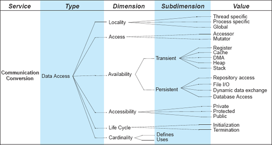
The space of options available to a software engineer for constructing data access connectors is shown in Figure 5-6. A data access connector could enable global access; allow mutating (that is, changing) the data; it could provide persistent access through file I/O; its cardinality would typically be a single entity that defines the data, but multiple entities that use the data; and so on.
Linkage connectors are used to tie the system components together and hold them in such a state during their operation. Linkage connectors enable the establishment of ducts—the channels for communication and coordination—that are then used by higher-order connectors to enforce interaction semantics. In other words, linkage connectors provide facilitation services.
Once ducts are established, a linkage connector may disappear from the system or remain in place to assist in the system's evolution. Examples of linkage connectors are the links between components and buses in a C2-style architecture (recall Chapter 4) and dependency relationships among software modules described by module interconnection languages (MIL) (DeRemer and Kron 1976).
The space of options available to a software engineer for constructing linkage connectors is shown in Figure 5-7. Compared to the preceding dimensions, this is not a particularly rich connector dimension. The reference to linked components can be implicit, possibly even parameterized and mutable, or explicit. The granularity dimension refers to the size of components and level of detail required to establish a linkage. The subdimensions of granularity (unit, syntactic, and semantic) were directly influenced by Dewayne Perry's foundational study of software interconnection models (Perry 1987):
Unit interconnection specifies only that one component—which can be a module, an object, or a file—depends on another. Examples of unit interconnection are configuration management and system building facilities such as Make.
Syntactic interconnection refines this relationship and establishes links between variables, procedures, functions, constants, and types within the linked components. This information can be used in static analysis (For example, locating unreachable code within a module) and smart compilation, where only the changed portions of a system are recompiled.
Semantic interconnection specifies how the linked components are supposed to interact. Semantic interconnection ensures that the interaction requirements and constraints are explicitly stated and satisfied. This typically takes the form of an interaction protocol, such as those discussed in the context of architectural modeling and analysis in Chapter 6 and Chapter 8 respectively.

The cardinality of a linkage connector refers to the number of places in which a system resource—such as a component, procedure, or variable—is defined, used, provided, or required. Typically, a resource is defined and/or provided in a single location and used or required from multiple locations. Finally, a linkage connector can establish the binding between components very early (that is, prior to system compilation), early (that is, during compilation), or late (that is, during the system's execution).
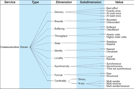
Streams are used to perform transfers of large amounts of data between autonomous processes. Stream connectors therefore provide communication services in a system. Streams are also used in client-server systems with data transfer protocols to deliver results of computation. Streams can be combined with other connector types, such as data access connectors, to provide composite connectors for performing database and file storage access, and event connectors, to multiplex the delivery of a large number of events. Examples of stream connectors are Unix pipes, TCP/UDP communication sockets, and proprietary client-server protocols.
The space of options available to a software engineer for constructing stream connectors is shown in Figure 5-8. For example, a stream-based connector may be unnamed, as in Unix pipes; it may provide synchronous, remote interaction via structured data; it may guarantee at least one delivery; its cardinality may be binary, that is, a single sender and a single receiver; finally, its state value could be determined by a bounded buffer.
When components are aware of the presence of other components but cannot make assumptions about their needs and state, arbitrators streamline system operation and resolve any conflicts (thereby providing facilitation services), and redirect the flow of control (providing coordination services). For example, multithreaded systems that require shared memory access use synchronization and concurrency control to guarantee consistency and atomicity of operations. Arbitrators can also provide facilities to negotiate service levels and mediate interactions requiring guarantees for reliability and atomicity. They also provide scheduling and load balancing services. Arbitrators can ensure system trustworthiness by providing crucial support for dependability in the form of reliability, safety, and security.
The space of options available to a software engineer for constructing arbitrator connectors is shown in Figure 5-9. Arbitrator connectors can aid with system fault handling, by determining and trapping component faults before they propagate. They can also ensure the appropriate concurrency semantics among the interacting components. For example, arbitrators can employ mechanisms, such as semaphores or monitors, to control access to the interacting components' resources. Arbitrator connectors may also support transactions and guarantee different levels of security (see Chapter 13). Finally, they can control the interacting components' execution scheduling. A specific example of arbitrator connectors is discussed in Section 5.5.
Adaptor connectors provide facilities to support interaction between components that have not been designed to interoperate. Adaptors involve matching communication policies and interaction protocols among components, thereby providing conversion services. These connectors are necessary for interoperation of components in heterogeneous environments, such as different programming languages or computing platforms. Conversion can also be performed to optimize component interactions for a given execution environment. For example, a distributed system may rely on remote procedure calls (RPC) for all interactions across process boundaries; if two interacting components are co–located within the same process for a given time period, a remote procedure call may be seamlessly converted to a local procedure call during that time. Adaptors may also employ transformations (for instance, table look-ups) to match required services to the available facilities.

The space of options available to a software engineer for constructing adaptor connectors is shown in Figure 5-10. Examples of adaptors include virtual memory translation; Daniel Yellin and Robert Strom's adaptors (Yellin and Strom 1994), which match incompatible component interaction protocols; virtual function tables used for dynamic dispatch of polymorphic method calls; and Robert DeLine's packagers, which separate a component's internal functionality, referred to as essence, from the manner in which it is accessed (DeLine 2001). XML meta–data interchange (XMI) is a relatively recent approach that supports interchange of models between applications and performs data presentation conversion.
Distributor connectors perform the identification of interaction paths and subsequent routing of communication and coordination information among components along these paths. Therefore, they provide facilitation services. Distributor connectors never exist by themselves, but provide assistance to other connectors, such as streams or procedure calls. Distributed systems exchange information using distributor connectors to direct the data flow. Distributed systems require identification of component locations and paths to them based on symbolic names. Domain name service (DNS), routing, switching, and many other network services belong to this connector type. Distributors have an important effect on system scalability and survivability.

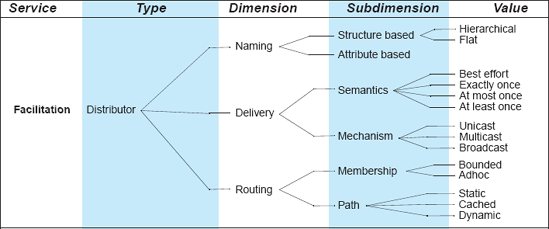
The space of options available to a software engineer for constructing distributor connectors is shown in Figure 5-11. Issues that are particularly important in distributed systems are resource naming, semantics and mechanisms of data delivery, and characteristics of routing.
The reader should be familiar at least with the frequently used procedure call and shared data connector types. It likely that the reader has seen or used several of the other connector types, such as distributors or adaptors, and has also been exposed to composite connectors. Furthermore, Chapter 4 introduced a number of connectors in the different Lunar Lander examples.
In this section, we illustrate the connector classification discussed above with four composite distribution connectors that are in wide use today: event-based, grid-based, client-server-based, and peer-to-peer-based (or P2P-based) connectors. These connectors distribute large amounts of content over a wide area network, such as the Internet. Such connectors are used in disseminating music, movies, scientific data, and so on. Several implementations of these connectors are in wide use by a number of research, industry, and government projects, as well as a large number of individuals around the world.

Figure 5-12. Data distribution connectors involve a type of invocation (via arbitrator, event, or procedure call connectors), data access, stream, and distribution. Cardinality is indicated accordingly on the relationship arrows, where * refers to the cardinality of "many."
Distribution connectors can be described as different combinations of six of the connector types defined in the classification of Section 5.4. The exact combination of the six types' dimensions varies across the different distribution connectors, but in general, each distribution connector performs some form of data access, involving a stream-based reading (and packaging) of data, and distribution of the data to end users. Some connector classes are invoked via procedure calls (for example, client-server–based) while others are invoked via events (for example, event-based), or arbitration (for example, P2P-based). Figure 5-12 illustrates the choices and the relationships.
The remainder of this section describes each of the four data distribution connectors using the connector classification from Section 5.4. The seemingly verbose description of the connectors is necessary: it reflects the number of concerns an architect has to consider when selecting and composing connectors for a specific system, as well as the number of decisions that will be made in the process.
The event-based data distribution connectors are compositions of four of the connector types from Section 5.4: event, data access, stream, and distributor. These connectors send and receive data through asynchronous notifications called events. Events may arrive according to some fixed periodic schedule or at discrete aperiodic intervals. Typically, there are many producers and consumers of data in event-based distribution connectors. For example, science data servers (producers) may alert scientists (consumers) of the availability of new data sets. Event-based distribution connectors often employ an asynchronous best-effort delivery method for data, making no guarantees as to the completion or time of data deliveries. Data delivery events sent through the connectors can be prioritized, tailored to different use cases or deployment environments, and specified by system users. Events can be delivered using prioritized threaded queues, be locally or remotely managed, or be delivered using user registered preferences and the publish-subscribe delivery mechanism.
Event-based distribution connectors can access and mutate data at both the producer and consumer ends. Event-based distribution connectors themselves access transient and persistent data, both public and private. They communicate with transient session-based stores such as shared memory stores [for example, Apache's Derby (Apache Software Foundation)]. They also communicate with persistent stores such as repositories, databases, file systems, and Web pages.
After data access by event-based distribution connectors, data is typically packaged into streams, both structured and raw, using a best effort approach, with bounded packet size and data buffering. Streams can be identified via named uniform resource identifiers (URIs), and constructed using the asynchronous mode of operation. Streams may be constructed either locally or remotely, depending upon how the data was accessed.
Stream-based data is distributed from data producers to data consumers using a naming registry, via either a hierarchical or flat naming model. Data streams are delivered as events using best effort delivery and any combination of the unicast, broadcast, and multicast delivery mechanisms. Routing of events is typically determined by the specific network layer of the connector's deployment environment.
Example instances of event-based data distribution connectors include the Siena publish-subscribe middleware (Carzaniga, Rosenblum, and Wolf 2001), the Prism-MW middleware (Malek, Mikic-Rakic, and Medvidoviç 2005), and its subsequent extension allowing grid resource location and discovery, called GLIDE (Mattmann et al. 2005).
The grid-based data distribution connectors are compositions of four of the connector types from Section 5.4: procedure call, data access, stream, and distributor. These connectors move and deliver large amounts of data between software components deployed in the grid environment—a virtual network of shared computing and data resources. Although the grid is further discussed in Chapter 11, this section will outline the architecture of the corresponding connectors. The reader may find it useful to return to this section again after reading Chapter 11.
Grid-based distribution connectors are invoked via a named, synchronous procedure call, often as a Web service call sent using the Simple Object Access Protocol (SOAP) (Mitra 2003). User authentication credentials are provided to the connector for integration with the Grid Security Infrastructure (GSI), a highly secure toolkit based on key pairs and certificate authorities. URLs sent via the connector invocation describe where the data is and where it is to be sent (that is, who the consumers are). Parameters are passed by value using "keyword equals value" semantics, with control messages being logged to the Grid API log layer.
Grid-based distribution connectors access and mutate transient and persistent data, both private and public, as long as there is some type of standard API (for instance, dynamic data exchange over XML, a repository access, or file I/O) for accessing it.
Data access through a grid connector is typically packaged as a stream of bytes (or blocks, configured via a parameter) with exactly-once delivery and (configurable) bounded buffering provided by the network's TCP/IP level. Data can be structured or raw. Buffering and throughput of data are parallelized via multiple concurrent time-out synchronous TCP/IP streams. Streams are named stateful URLs and URIs, and can exist both locally and remotely, depending upon where the data was accessed. A stream can be delivered to many consumers.
Grid-based distribution connectors distribute data using the grid environment for naming and location, including the Grid Meta–data Catalog Service (MCS) and Replica Location Service (RLS) components, and named URLs and URIs. Naming can be hierarchical, with resources and locations sharing parent-child relationships via the MCS. Alternatively, naming and discovery can be flat, structure-based. Data is delivered via parallelized unicast exactly once using TCP/IP concurrent streams, flooding the underlying network to its saturation, thus making the most efficient use of the available bandwidth possible. Reliability measures allow redelivery of lost packets if necessary, as well as partial data transfers, both sequential and out of order. Routing of data is handled by the underlying TCP/IP network layer.
Example instances of grid-based distribution connectors include the GridFTP software, bundled along with the Globus Grid Toolkit (The Globus Alliance), and the large files transfer protocol, or bbFTP (Farrache 2005).
The client-server-based distribution connectors allow seamless distribution of data between distributed systems using RPC. They are compositions of four of the connector types from Section 5.4: procedure call, data access, stream, and distributor. These connectors are invoked via a synchronous remote procedure call that appears (to the consumers of data) as if it were a local method call. Keyword (named) parameters are passed to the method call to specify the distribution constraints, with parameters being passed by value or reference, depending upon the underlying remote procedure call implementation. Methods can have return values, which typically must conform to a standard set of primitive data types that are supported on all machines involved in the data distribution. Methods are interactions between one sender and one receiver, typically the producer of the data and its consumer, respectively.
Upon invocation, the client-server-based distribution connector engages in a data access, grabbing and mutating persistent and transient data. After data is accessed, it is packaged into streams that are delivered using exactly-once delivery and bounded packet size managed by the underlying TCP/IP protocol. Data can be raw or structured in the stream. Stream throughput is measured in atomic units (bits per second), and streams are identified using stateful Uniform Resource Names (URNs). Streams can be local or remote, depending on where the data was accessed or packaged.
Data is distributed from client-server-based connectors using a naming registry to locate the requesting consumer of data. Data is delivered through method (or interface) parameters and return values. It is sent exactly once, using the unicast delivery mechanism. Routing is performed by the underlying TCP/IP network using static membership identified via a naming registry.
Example instances of client-server-based data distribution connectors include HTTP/REST (recall Chapter 1), Java RMI, CORBA (recall Chapter 4), FTP, SOAP, and many commercial UDP technologies.
The P2P-based data distribution connectors are compositions of four of the connector types from Section 5.4: arbitrator, data access, stream, and distributor. These connectors are unlike the other three categories. Rather than providing some sort of initial procedural or event-based invocation, these connectors typically rely on arbitration as a means of synchronization and invocation. Arbitration involves control flow redirection between distributed resources, or peers, operating in a networked environment. Arbitrators can negotiate protocols, scheduling, and timing issues. Fault handling and parameter passing is handled in an egalitarian fashion via voting and point-to-point or point-to-many communication between peers or groups of peers. P2P-based distribution connectors use rendezvous as a mechanism to achieve concurrency and scheduling. Transaction support is often available, and invocation can be rolled back if necessary.
Upon invocation, peers in a P2P-based distribution connector engage in data access, accessing transient (both process- and thread-specific) and persistent (for instance, repository, file I/O, and so on) data. Since peers can come and go in a P2P-based scenario, for the most part data access is transient in nature: A peer need not stick around for the entire distribution.
Data is accessed and packaged via streams, using a best effort bounded mechanism. Data can be structured or raw, as long as it can be organized into identifiable chunks that can be retransmitted and shared between peers handled by the connector. Streams are named URNs, typically identified using some hashing algorithm (such as SHA-1 or MD5), and are available both locally and remotely depending upon where the data was accessed or packaged.
Data is distributed in the P2P-based distribution connectors by locating other peers that have pieces of data a user wants to obtain or distribute. Location of other peers is based upon attributes such as resource type, SHA-1, and other domain-specific attribute meta–data (for instance, for movie files "production company" might be used or for music "artist name"). Delivery occurs in the form of chunks, sent to and from remote peers using best effort or at least once semantics over unicast and multicast transmission channels. Routing, while influenced by the underlying network layer, is handled by some sort of tracking mechanism, sometimes called trackers or super peers. Tracking mechanisms allow location of chunks of data streams that need to be distributed or obtained in a P2P-based connector.
Example instances of the P2P-based distribution connector class include BitTorrent (Cohen 2003) and JXTA-based data distributors, such as the Peerdata project at NASA's Jet Propulsion Laboratory. P2P systems employing such connectors are discussed in Chapter 11.
This section provides general guidelines for software architects in selecting connectors that meet their needs. The section discusses the issue of connector compatibility: Understanding which connectors, or connector dimensions, are and are not compatible is particularly important in cases where composite connectors are needed.
In selecting a software connector that meets the particular needs of a given (sub)system, a software architect must perform at least the following steps. Note that the descriptions of the steps are relatively general, meaning that this process places significant responsibility on the software architects and requires a great deal of familiarity with the technical details of connectors that are at their disposal.
Select the specific set of interacting components. Different sets of components, even in the same system, may have different interaction needs. This is why it is important for the architect to focus only on those components for which the desired connector is needed. This and the subsequent steps are repeated for each such component set, that is, for as many distinct connectors as are needed in the system.
Determine the interaction services the components need. It is critical to identify the precise characteristics of the components' interaction. This will likely involve studying the components' architectural descriptions, and may also require considering the implementation language and/or framework.
Based on the identified interaction services, determine a subset of the eight connector types that comprise the initial candidate set for providing those services. It is sufficient to establish that the connector types chosen in this step may be good candidates for supplying the needed services.
Evaluate each connector type from the chosen subset based on the details of the interaction requirements. Study these in light of the connector types' dimensions, subdimensions, and values. Eliminate any connector types whose usage is deemed to result in a suboptimal interaction solution for the specific set of components under consideration.
For each of the remaining candidate connector types, set the values for the necessary dimensions and subdimensions as appropriate. Identify the best (most natural) candidate connectors. This will require performing a trade-off analysis among multiple possible solutions. It may also result in selecting a composite connector, which combines features of multiple types, as further discussed below.
The classification of connectors described in Section 5.4 thus serves as the foundation for synthesizing new connectors as well as analyzing the compatibility of connector dimensions. Instantiating dimensions of a single connector type by choosing one or more values forms a simple connector species. On the other hand, using values of dimensions from different connector types leads to a composite (higher-order) connector species. Many real-world scenarios will force an architect to compose such higher-order connectors to satisfy all application requirements.
The reader should note that creating unprecedented, composite connectors is not a trivial task. At the least, this requires developing a deep understanding of the connectors' complementary, orthogonal, and incompatible characteristics. Without such an understanding, the resulting integration process may be misguided and the developed solutions suboptimal, or worse, completely ineffective. Examples of this have been documented in the literature [for example, in the well known case of the interactions among the large components used in the Aesop system (Garlan, Allen, and Ockerbloom 1995)].

In the absence of a set of concrete, well-understood, and widely adopted rules for defining composite connectors, it becomes difficult to guide this process. Recent research by, for example, Bridget Spitznagel and David Garlan (Spitznagel and Garlan 2003) suggests some specific formalisms and strategies that can be adopted to address connector composition. However, ultimately a comprehensive classification of connectors, such as the one presented in this chapter, is necessary (though not sufficient) to create a general set of guidelines that specify the conditions under which two or more connectors can be composed. We discuss this issue in more depth next.
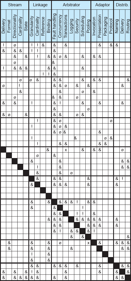
The connector taxonomy introduced in Section 5.4 can be leveraged to identify potential mismatches between incompatible connector dimensions, and to avoid such combinations. Figure 5-13 shows a compatibility matrix for the connector dimensions identified in the classification from Figure 5-4 through Figure 5-11. The matrix provides guidance regarding which combinations of dimensions are necessary and which should be avoided; the empty cells in the matrix denote combinations that are possible, but not required. The sparseness of the matrix suggests that the allowed design space of connectors is very large based on their current understanding. At the same time, some pitfalls are known to exist. Four kinds of rules for combining connector dimensions can be identified: requires, cautions, restricts, and prohibits.
The requires rule indicates that the choice of one dimension in one connector species mandates that another dimension be selected in another connector species; it also allows all possible combinations of the values of the given dimension and its required co-dimension. For example, if a distributor and an adaptor connector are composed, distributor's delivery requires that the adaptor support presentation conversion, that is, that it allow data to be marshaled for transport across address spaces.
Requires is a chaining rule and is used as the starting point for constructing the base connector species. For example, an event connector that requires delivery semantics also needs a notification dimension, which in turn requires cardinality, synchronicity, and mode. This chaining rule results in identification of dimensions that are mandatory in all species of a connector type, and those that are optional. In Figure 5-13, the mandatory dimensions are in boldface, whereas the optional dimensions are in regular font.
The cautions rule indicates that certain combinations of values for two connector dimensions that are required to be used in tandem, while valid, may result in an unstable or unreliable connector. For example, a component being invoked implicitly should not have multiple entry points since an implicit invocation mechanism cannot choose among the entry points. Another example is the relationship between arbitrator connector's concurrency dimension and data access connector's locality dimension: the granularity level at which concurrency is supported by the former (heavy-weight versus light-weight) should match the level at which locality is supported by the latter (process-specific versus thread-specific).
The restricts rule is used to indicate that the two dimensions are not required to be used together at all times, and that there are certain combinations of their values that are invalid. For example, thread-specific data access cannot use heavy-weight concurrency (see the intersection of data access-locality with arbitrator-concurrency). Likewise, passing parameters by name when those parameters have only transient availability can cause the parameters' values to disappear, be changed, or be affected by some read-modify-write condition; the problem is exacerbated when these parameters are passed by reference and the procedure has no place to store their new values or to access the old ones (see the intersection of procedure call-parameters with data access-availability).
Finally, the prohibits rule is used to exclude any combination of two dimensions from being used and indicates total incompatibility of the dimensions. For example, stream delivery cannot be built on transactional atomicity (see the intersection of stream-delivery with arbitrator-transactions). As can be seen in Figure 5-13, there are relatively few instances of the prohibits relationship. This is a positive indicator, as it shows that most connector combinations are legal at least under some circumstances. At the same time, the large numbers of restricts and cautions relationships in Figure 5-13 also indicate that software architects must be careful when composing connectors.
While the above discussion was restricted to the binary combinations of connector dimensions, the compatibility relations between dimensions are transitive. In other words, the compatibility rules can be successively applied to determine the n-ary compatibility between dimensions. The binary relations outlined in this section would serve as a necessary starting point for analyzing the n-ary relations.
Explicit, targeted study of software connectors is a relatively recent occurrence. There still are many details that need to be uncovered and understandings improved. Figure 5-13 is indicative of this: The sparser sections of the compatibility matrix argue for the need for greater understanding of certain combinations of connector types (such as data access and stream). It is reasonable to expect that, as our understanding of connectors improves over time, the compatibility matrix, as well as the rationale behind it, will also evolve.
Every software system employs connectors, frequently many of them. In complex distributed systems in particular, connectors can be the key determinants of whether the desired system properties will be met. This observation is often made, yet connectors are not always given first-class status in software systems, and have certainly not been studied to the same extent as components.
This chapter has presented a detailed study of software connectors. At the most basic level, each connector establishes a conduit (which can be thought of, and referred to, as a virtual channel or duct) for two or more components to interact by exchanging control and data in a software system. The actual manner in which data and/or control are exchanged, however, and the specific characteristics of that exchange, can vary widely. This is what makes the space of software connectors quite large and complex.
As this chapter has argued, the space of connectors can be better understood by considering the role (or roles) played by a given connector and the type (or types) of interaction supported by the connector. At the same time, the large number of variation points for each connector type (the dimensions, subdimensions, and values introduced in Section 5.4) require that the (in)compatibilities among connectors be considered carefully. While this area clearly requires further study, the existing body of knowledge, if applied judiciously, can be a great aid to software architects and developers.
The following several chapters will use this as well as the preceding chapters as the foundation for introducing the reader to a number of key activities in architecture-driven software development. Chapter 6 focuses on the principles of architecture modeling and presents the details of a number of software architecture description languages. Chapter 7 introduces the reader to the approaches for visualizing software architectures. Chapter 8 provides an overview of architectural analysis. Chapter 9 discusses the challenges and solutions for architecture-based system implementation. Finally, Chapter 10 focuses on the postimplementation concerns of system deployment and run-time mobility.
How are connectors different from components?
What is a duct? What purpose does it serve?
What is the difference between the transfer of control and the transfer of data?
Name and describe the four possible roles played by a connector.
How is facilitation different from conversion?
Name and briefly describe the eight different connector types.
Why is connector composition challenging?
Are there connector types that can always be composed?
Are there types that can never be composed?
What are data-intensive connectors?
What characteristics do all data-intensive connectors share?
For each connector type discussed in this chapter, try to identify a specific connector species that belongs to that type.
For the connectors identified in the previous question, enumerate the dimension and subdimension values that each of the connector species takes.
Analyze the connectors used in the different Lunar Lander examples in Chapter 4 to determine the connector types to which they belong. Specify the values they take for different dimensions and subdimensions.
Consider the Aesop system developed by Garlan et al. and described in (Garlan, Allen, and Ockerbloom 1995). Develop a detailed strategy for integrating Aesop's four major components by explicitly treating its connectors. Would your strategy have helped Aesop's developers to deal with the architectural mismatches among the components more effectively than their adopted strategy?
Select a software system with which you are intimately familiar. Isolate one of the connectors in the system (for example, a procedure call connector). Replace that connector with a connector of a different type (for example, an event connector). What were the required steps in doing so? Discuss the lessons learned.
Select a software system with which you are intimately familiar and which uses mostly procedure call connectors. Replace all procedure call connectors in the application with explicit, named connectors, thereby completely decoupling the interacting components. Discuss the relative merits of the two applications' architectures.
Repeat the above exercise by changing one or more connectors that support synchronous interaction between components with connectors that support asynchronous interaction. What challenges did you face in accomplishing this task? Does the modified application exhibit the same behavior as the original application? Why or why not?
Several open-source systems, available from Source Forge.net and similar online repositories, are ac- companied by thorough design documentation. Select at least two open-source systems and study their architectures. Identify their connectors. Classify the connectors according to their types. Can you spot any trends in the systems' connector usage?
Mehta et al. (Mehta, Medvidović, and Phadke 2000) have argued that the Linux Process Scheduler subsystem identified in the study by Bowman et al. (Bowman, Holt, and Brewster 1999) is, in fact, a connector. Investigate the implications of this decision. In order to do so, you may want to consider treating Process Scheduler as a component, or as a subarchitecture comprising a composition of finer-grained components and connectors. Were Mehta et al. correct in their decision? Does their decision fundamentally alter the architecture of Linux, or one's understanding of it?
This chapter has suggested that, architecturally, the different classes of data-intensive connectors are similar to a certain extent. Select two such widely used connectors from different categories—for instance, client-server and peer-to-peer. Based on their architectures discussed in Section 5.5, outline a strategy for converting one connector into the other.
Study the Question 10's two connectors' architectures and implementations in more detail. Was your conversion strategy viable? If so, proceed with the conversion. If not, discuss the reasons why, adjust your strategy as appropriate, and proceed with the conversion.
Software connectors have been an important facet in developing large, complex software intensive systems for a long time. While they may not have been the primary focus of study, and may not have been identified explicitly, connectors figured prominently in the operating systems, programming languages, distributed systems, computer networks, and middleware literature [for instance (Reiss 1990), (Colouris, Dollimore, and Kindberg 1994), (Yellin and Strom 1994), (Orfali, Harkey, and Edwards 1996)].
The explicit focus on software connectors is more recent and has emerged from the body of work dealing with software architecture. Perry (Perry 1987) provided the needed foundation in his study of software interconnection models. Perry and Wolf (Perry and Wolf 1992) were the first to suggest connectors as first-class entities in a software architecture, and Shaw and Garlan (Shaw 1994; Shaw, DeLine, and Zelesnik 1996; Shaw and Garlan 1996) soon followed suit. Allen, Garlan, and Ockerbloom (Garlan, Allen, and Ockerbloom 1995) demonstrated that explicit connectors can provide a substantial aid in system specification, and can carry significant, inherent analytical power.
Several researchers have tried to classify connectors as an aid to software architects in making the most appropriate design choices. An early such effort by Hirsch, Uchitel, and Yankelevich (Hirsch, Uchitel, and Yankelevich 1999) was limited in scope, but it directly inspired the more detailed study by Mehta, Medvidović, and Phadke (Mehta, Medvidović, and Phadke 2000), which has been referenced extensively in this chapter. Bálek and Pláš il (Balek and Plasil 2001) have proposed a formal connector model for dealing with software deployment (recall Chapter 3). In particular, they posit that the basic set of dynamic services that a connector should provide to aid deployment maps directly to the key service categories in Mehta et al.'s taxonomy: control and data transfer, interface adaptation and data conversion, access coordination and synchronization, communication intercepting, and dynamic component linking. Bálek and Plášil additionally demonstrate that their connectors can be composed to provide more advanced interaction services, in a similar vein to Spitznagel and Garlan's later work (Spitznagel and Garlan 2003).