
Implementation is the one phase of software development that is not optional. Regardless of how well the requirements have been captured or how carefully the architecture has been designed and reviewed, software systems must be implemented in code to achieve their ends. Architecture is used to capture important design decisions about a system, using sound engineering principles and knowledge to increase confidence that the target system's qualities match the expectations of its stakeholders. To imbue these qualities in the target system, the implementation must be derived from its architecture.
In terms of implementation, architecture is both prescriptive and restrictive. It is prescriptive in the sense that it gives implementers direction on what to produce—how to structure code modules, how they should be interconnected, and how they should behave. It is restrictive in the sense that its guidelines—particularly those specified in the architectural style—tell developers what they may not do: the forms of communication that are prohibited, the kinds of behaviors or system states that are not allowed, and so on.
The problem of relating architecture to implementation is one of mapping. Concepts defined at the architecture level should be directly connected to artifacts at the implementation level. This correspondence is not necessarily one-to-one. For example, in general, a software component or connector will be implemented using many code and resource artifacts. Likewise, a single software library may be shared among several component implementations (as long as its manner of use does not violate style rules). When this mapping is not maintained, architectural degradation can occur—specifically, the gradual deviation of a system's implementation from its architecture. This generally makes software harder to understand and maintain, and makes it difficult to achieve or retain the qualities embodied by the architecture.
Properly implementing a system so that the architecture survives in the implementation requires a well-formed understanding of how concepts in the architecture (and the architectural style) map onto implementation technologies such as programming languages, development environments, reusable libraries and components, middleware, and component models. Implementation technologies such as middleware and component libraries can help, but they can also hinder: They nearly always come with their own assumptions that can influence or get in the way of architectural decisions made earlier. Even concepts we take for granted, such as object-oriented programming, can have architectural influences. In this chapter, we discuss techniques and technologies for creating and maintaining mappings between architecture and implementation.
We also introduce and focus on a concept known as an architecture implementation framework, which is software that bridges the gap between architectures and implementation technologies. We discuss how to identify, evaluate, and create new frameworks. We also relate frameworks to other, similar technologies such as middleware and component frameworks.
Outline of Chapter 9
9. Implementation
9.1 Concepts
9.1.1 The Mapping Problem
9.1.2 Architecture Implementation Frameworks
9.1.3 Evaluating Frameworks
9.1.4 Middleware, Component Models, and Application Frameworks
9.1.5 Building a New Framework
9.1.6 Concurrency
9.1.7 Generative Technologies
9.1.8 Ensuring Architecture-to-Implementation Consistency
9.2 Existing Frameworks
9.2.1 Frameworks for the Pipe-and-Filter Architectural Style
9.2.2 Frameworks for the C2 Architectural Style
9.3 Examples
9.3.1 Implementing Lunar Lander in the Pipe-and-Filter Style Using the java.io Framework
9.3.2 Implementing Lunar Lander in the C2 Style Using the Lightweight C2 Framework
9.4 End Matter
9.5 Review Questions
9.6 Exercises
9.7 Further Reading
Here, we will discuss concepts and issues related to architecture-based implementation.
Implementing an architecture is a problem of mapping—specifically, mapping design decisions to specific implementation constructs that realize those decisions. From a software-quality perspective, this mapping is a form of traceability. In general, the term traceability can refer to any mechanism for connecting different software artifacts; in this context we specifically mean traceability from architecture to implementation. Choosing how to create and maintain this mapping is critical in architecture-based development. Here, we discuss implementation mappings for several kinds of design decisions discussed in Chapter 6.
Components and Connectors. Design decisions about components and connectors partition the application's functionality into discrete elements of computation and communication. In general, programming environments provide mechanisms such as packages, libraries, or classes that are used to partition functionality in implementations. Here, the challenge is to maintain a mapping between the partitions established by the architecture-level components and connectors and the partitions established by the implementation-level packages, libraries, classes, and so on. If implementations are not partitioned according to the component and connector boundaries specified in the architecture, then component boundaries may break down and cause architectural drift and erosion.
Interfaces. At the architectural level, interfaces can be specified in many different ways. If interfaces are specified in terms of method or function signatures similar to those in the target programming language, mapping is a straightforward process of translating the method signatures into code. However, if the architecture-level interface definition is more complex—specifying a protocol or set of state transitions, then greater effort will be required to create an appropriate implementation.
Configurations. At the architectural level, configurations are often specified as linked graphs of components and connectors. These graphs specify and constrain how the components and connectors interact through their interfaces. The same interactions and topologies must be preserved in the implementation. Many programming languages include features that allow one module to refer to another module by way of its interface, rather than its implementation (for example, though explicitly defined interfaces as in Java, or function pointer tables in C). Additionally, some programming languages and middleware systems allow the use of reflection or dynamic discovery to connect and disconnect components at runtime. When these constructs are available, it is often possible for the implementation-level links between components and connectors to be specified independent of the components and connectors themselves, or even generated from the architecture description.
Design Rationale. Design rationale is a construct that often has no specific mapping to implementation, since it is not something that directly influences the functionality of the application. Often, the best way to retain design rationale during implementation is by writing it down in source-code comments or external documentation.
Dynamic Properties (Behavior). Depending on how they are modeled, architecture-level behavioral specifications can ease or facilitate implementation. Some behavioral specifications can be translated directly into implementation skeletons or even complete implementations. However, this is not always the case; formal behavioral specifications often lack bindings to programming-language–level constructs and therefore it is difficult to determine whether a behavioral specification is actually implemented correctly. Some behavioral specifications are more useful for generating analysis or testing plans than for implementations.
Non-Functional Properties. Implementing non-functional properties is perhaps one of the most difficult propositions in software engineering. The best way to accomplish this is through a combination of techniques—documenting rationale, inspections, testing, user studies, and so on. This difficulty is why refining non-functional properties into functional design decisions (when possible) is so important.
Architectures and implementations must inevitably co-evolve. Architectures can evolve because of changing requirements or increased understanding, and these changes must be propagated to the implementation. Likewise, discoveries and changes made during implementation will affect the architecture. Keeping architecture and implementation in sync is a challenging problem, involving issues of process, tool support, and organizational culture. Aspects of the mapping that lack strong traceability are often the first to diverge.
Maintaining the architecture-implementation mapping in the face of change depends on the process of change. One option is to mandate that all changes begin from the architecture—the architecture is changed first, the mappings to implementation are used, and then the implementation is updated through the use of automated tools or manual processes. This is effectively a one-way mapping. Another option is to allow changes to be initiated in either the architecture or the implementation. In this case, automated tools or manual processes are still used to update the other artifact. This is a two-way mapping.
Two-way mappings are better for detecting and resolving architectural drift and erosion, but they are also more complex and expensive to create and maintain. This is sometimes known as a round-tripping problem because changes have to be mapped from architecture to implementation and back again. Various strategies for maintaining both one-way and round-trip mappings are discussed in this chapter.
When developing a system, an ideal approach would be to define the architecture first and then select implementation technologies (programming languages, software libraries, operating systems, and so on) that most closely match its needs. This ideal is difficult to achieve—programming languages rarely have explicit support for architecture-level constructs. Moreover, selection of implementation technologies will often be driven by extrinsic or accidental factors such as cost, maturity, platform support, organizational culture, and even externally imposed or wrongheaded requirements specifications or standards.
An important strategy for bridging the gap between concepts in an architecture and a system's implementation technologies is to use (or develop) an architecture implementation framework (Malek, Mikic-Rakic, and Medvidović 2005).
Definition. An architecture implementation framework is a piece of software that acts as a bridge between a particular architectural style and a set of implementation technologies. It provides key elements of the architectural style in code, in a way that assists developers in implementing systems that conform to the prescriptions and constraints of the style.
By far, the most common example of an architecture framework in use today is the Standard I/O library in UNIX (University of California 1986) and similar operating systems. Although few developers may recognize it as such, it is actually a bridge between the pipe-and-filter style (which is character-stream oriented and concurrent) and procedural, nonconcurrent programming languages such as C. It provides architectural concepts such as access to interfaces via readable and writable character streams in a way that fits the target environment (for example, procedure calls). A fuller discussion of how the Standard I/O library serves as an architectural framework appears later in this chapter.
Architecture frameworks are effectively technologies that assist developers in conforming to a particular architectural style. However, most frameworks will not prevent developers from wandering outside the constraints of the style. For example, just because a UNIX program imports the Standard I/O library does not mean that the program will work in a pipe-and-filter style; it may read and write all its data from named disk files and ignore the standard input and output streams completely.
It is possible to develop applications in almost any architectural style without the use of an architecture framework. However, this usually means weaving the architectural concepts throughout the implementation and makes it difficult to develop and maintain them. In the cases where no framework exists for a particular programming language/operating system combination, developers will usually end up implementing a set of software libraries and tools that amount to an architecture framework anyway.
A natural question to ask is: How are frameworks represented in architectural models? From an architectural perspective, frameworks are often considered to be a substrate underlying all components and connectors. Therefore, it is unusual to see a framework modeled as a component or connector in the architecture itself. However, frameworks often include implementations for common components and connectors (such as those defined by the style—a pipe connector or an event-bus, for example) that serve as implementations for components and connectors that are specified in the architecture.
A single architectural style can be supported by a number of different, alternative frameworks. This can happen for a number of reasons. First, different programming languages and implementation platforms usually require different frameworks. For example, Java applications use classes in the java.io package (Harold 2006) to perform stream input and output; these classes are how Java implements functions similar to the C standard I/O library. C++ programmers can either use the object-oriented iostream library or the procedural stdio library for the same purpose. Each of these architecture frameworks bridges the same architectural style (pipe-and-filter) to different implementation technologies (Java, C++, or C).
Sometimes, multiple frameworks for the same combination of style, programming language, and operating system will be developed. Usually, these frameworks distinguish themselves based on different qualities or capabilities. A good example is the New I/O (java.nio) package in Java (Hitchens 2002). Like the older java.io package, java.nio allows programs to read and write data streams from various sources. However, the New I/O package provides enhanced capabilities such as native support for buffering, better control over synchronization, and the ability to use fast data transfer techniques such as memory mapping. Users can choose the appropriate framework for their application based on the quality needs of those applications.
Frameworks, like any software system, can vary widely along nearly any quality dimension. This is why many frameworks are often developed to support the same architectural style in the same environment. Evaluating a framework, then, is similar to evaluating any important software component.
An architecture framework brings together three key elements: an architectural style, a programming language, and an operating system. One of the most basic criteria for evaluating a framework, then, is platform support. Once an architectural style has been identified, the availability of architecture frameworks for a target programming language/operating system combination can be determined. If the project has the freedom to select the implementation platform based on the architecture (which is becoming increasingly rare as software systems are more and more likely to run on existing platforms already in the field) then the availability of suitable architecture frameworks should be a criterion for platform selection.
One quality that is particularly important in architecture implementation frameworks is fidelity, specifically fidelity to the target architectural style. To be useful, a framework need not provide direct implementation support for every single design decision in its target style; for example, it may provide communication mechanisms but leave the concurrency of the architecture up to the individual component implementers. Furthermore, frameworks often provide support for following stylistic constraints, but not enforcement; that is, the framework will make it easy for implementers to follow the constraints of the style, but will not explicitly prevent them from breaking the constraints. More faithful frameworks are generally better at preventing or avoiding architectural drift and erosion. However, this generally comes at a cost because the frameworks are more complicated, bigger, or less efficient.
Architectural styles induce certain design decisions and constraints on applications. Frameworks can do the same thing—ideally, the decisions and constraints induced by the framework are the same as those induced by the target style. However, styles often leave many aspects of a system unconstrained, and frameworks have the additional responsibility of supporting the concrete implementation activity. For these reasons, frameworks may induce additional constraints on applications. For example, a framework might assume that the system will be instantiated and configured only by the framework, or that individual components and connectors will not start their own threads of control, or that each software component in the architecture can be associated with a module in the target programming language.
Problems can occur when the assumptions of a framework conflict with the assumptions of other implementation technologies used on a project. Consider an architecture framework for an object-oriented programming language. This framework might require that every component have a main class that is derived from a base class provided by the framework. However, the project might include several GUI elements, and the GUI toolkit may require that GUI element classes extend base classes provided by the toolkit. If the programming language is one that does not support multiple inheritance (like Java) there is a serious mismatch between the GUI toolkit and the implementation framework. This situation may not even be an architectural mismatch; it is a mismatch of particular implementation decisions. Nonetheless, strategies must be identified to alleviate this situation.
Thus, when evaluating an architecture framework, it is important to enumerate the assumptions it makes and compare those with the assumptions made by other components, toolkits, libraries, and environments with which the application will interact. Sometimes, workarounds can be developed, especially if the mismatch is a low-level implementation detail. However, if the mismatch is architectural, this might call into question the compatibility of the architectural style itself with the choice of implementation technologies for the implemented application.
In general, architecture frameworks add a layer of functionality between the application and the hardware it runs on. One of the primary dangers of introducing new layers is a decrease in application efficiency. This concern is especially important when dealing with architecture frameworks, since they tend to pervade the application. An architecture framework may mediate all communication between components in a system, for example, or dictate the concurrency policy for the entire application. When this is the case, efficiency should be a primary selection criterion for a framework.
Before committing to a framework, it is a useful exercise to run benchmarks on the framework with parameters derived from the target application to get a feel for the upper bound of application performance using the framework. For example, if a framework can exchange 10,000 messages per minute in a dummy application whose sole purpose is to exchange messages as quickly as possible, it is not realistic to build an application with that framework that will exchange 20,000 messages per minute.
As noted above, the issues involved in selecting an architecture framework are very similar to those involved in selecting any software component. It could be argued that because frameworks have such a pervasive effect on applications, they are the most critical element of all to select. Qualities such as size, cost, ease of use, availability of source code, reliability, robustness, portability, and many others are all important when choosing a framework.
A spectrum of technologies exists to integrate software components and provide services above and beyond those provided by a given programming language/operating system combination. These technologies go by a number of different names: middleware, component models (or component frameworks), and application frameworks. We will refer to these systems collectively as "middleware." Popular examples include CORBA (Object Management Group 2001), JavaBeans (JavaSoft 1996), COM/DCOM/COM+ (Sessions 1997), .NET, Java Message Service (JavaSoft 2001), various Web Services technologies, and so on.
There are many similarities between architecture frameworks and middleware. Both of them provide developers with implementation services that are not natively available in the underlying programming language or operating system. For example, CORBA middleware provides services such as remote procedure calls (RPCs) and the ability to dynamically discover the interfaces of objects. The JavaBeans component model introduces a new concept to Java: the bean, an object that follows certain interface guidelines that make it possible to compose beans more easily.
Architecture implementation frameworks are a form of middleware. The difference between traditional middleware and architecture frameworks is the focus on architectural style. Architecture implementation frameworks are implemented specifically to support development in one or more architectural styles. Here, the style is the primary artifact driving the implementation technology. Middleware is created based on the services that are provided, generally without regard to the style of the application being developed.
Middleware often constrains applications in ways that are similar to architecture frameworks. Middleware often influences how an application's functionality is broken up into components, how those components interact (often through middleware-provided services akin to connectors) and also the application's topology. These are generally architectural concerns. In this sense, middleware can induce an architecture or architectural style on an application (Di Nitto and Rosenblum 1999).
CORBA [and CORBA-like technologies such as COM and RMI (Grosso 2001)] are a good example of how middleware can influence application architectures. CORBA breaks up an application into objects that may reside on different hosts. Objects that participate in the application expose their own services through provided interfaces whose method signatures are specified in an interface definition language (IDL). Objects look up other objects through services such as naming services or trading services, and then call each other using a request-response pattern, passing only serializable parameters across the interface boundaries. Together, these constraints comprise an architectural style that might be referred to as the "distributed objects" style.
If system stakeholders have chosen the distributed objects style for their application, then CORBA-like middleware might serve as an ideal architecture framework. However, things are rarely this simple. Presented with an application to design, software architects have to make hundreds of design decisions. Choosing the application's architectural style is one of the most important decisions they will make. However, experienced architects are also familiar with many different middleware technologies and the advantages of those technologies. The services provided by many middleware technologies can be seductive, and often the capabilities of a particular middleware system will influence an architect's decision-making process. Architects must be especially careful to avoid having a middleware technology overly influence their designs.
Two major conflicts can arise between architectural styles and middleware:
The architectural style chosen for the application does not match that induced by the middleware chosen.
The application's designers chose a middleware first based on services provided and let this have an undue influence over the architectural style of the application.
When selecting implementation technologies, it is critical to understand that the quality benefits provided by that technology often come with architectural implications, which may not be compatible with your architecture's design. For example, CORBA provides the benefits of distribution and reflection, but in a form that induces systems that are based on objects that communicate by request-response procedure calls. This may cause certain architectural drawbacks, such as increased latency and synchronization. Allowing the choice of middleware to influence the architecture is backward: It is the tail wagging the dog. Architecture should influence your choice of middleware.
When there is an architectural mismatch between middleware and the target architectural style, several options are available:
Change the Style. The architectural style can be changed to better fit the middleware. This should be done only when the benefits of using the middleware outweigh the costs of adapting it to work with the target style.
Change the Middleware. The middleware can be adapted to better fit the architectural style. This strategy can be difficult because middleware packages are often large, complex, or proprietary.
Develop Glue Code. Architecture frameworks can be built on top of middleware, leveraging the parts of middleware that match, and working around the parts that do not. This way, neither the style nor the middleware itself has to be adapted.
Ignore Unneeded Middleware Services. Some middleware packages or component frameworks might provide a host of services that cut across many aspects of application development. However, it may be possible to use a subset of these services selectively, and ignore the services that are not compatible with (or relevant to) the target architectural style.
Hide the Middleware. Developers use middleware because it provides certain services. If those services are not necessarily cross-cutting, and can be applied at specific points in the architecture, then it may be possible to hide the middleware inside individual components or connectors. For example, if CORBA is being used only to facilitate communication between heterogeneous components running on different hosts, all CORBA-related code can be isolated within individual connectors that need cross-host communication. Other CORBA services such as lookup and dynamic interface discovery might be used entirely within the context of the connectors or simply ignored.
Many middleware packages provide services that are effectively communication-centric: They provide different mechanisms for heterogeneous components to communicate. If improving communication in an architecture is a goal, then using middleware as the basis for implementing connectors, rather than the whole application, can allow a system to avoid having the middleware's assumptions bleed into and corrupt the architecture's design decisions.
In this scenario, architects first should define and identify the capabilities required for a connector, ideally without regard to how that connector will be implemented. Then, middleware should be selected that can provide all (or most) of those capabilities and also fit with the other project goals. If capabilities are not provided directly by the middleware, they should be implemented as part of the connector's implementation. The result is a connector that fulfills the architectural need, rather than one that bows to assumptions made by middleware developers.
For example, a connector might be needed that provides message-passing support between a C++ component running on Linux and a Java component running on Windows. Two message-oriented middleware packages may be available: a commercial package that has C++ and Java support for both platforms, but is proprietary and expensive, and an open-source solution that supports both platforms but only C++ components. If budgets are tight, the open-source solution can be selected, and a Java Native Interface (JNI) adapter (Liang 1999) can be written to allow the Java component to communicate with the middleware.
Occasionally, circumstances motivate the development of a new architecture implementation framework. Good reasons to develop a new framework include:
The architectural style in use is novel.
The architectural style is not novel but it is being implemented on a platform for which no framework exists.
The architectural style is not novel and frameworks exist for the target platform, but the existing frameworks are inadequate.
Developing an architecture framework is a task that should not be approached lightly. These frameworks will impact almost every part of the applications built atop them and can be a make-or-break factor for the success of those applications, so great care should be undertaken in their design. Developing an architecture framework is, in many respects, like developing any other application—it requires the development of requirements, a design, input from many stakeholders, quality evaluation, and so on. As such, almost everything we have said in this book about developing applications in general can be applied to architecture frameworks. There are, however, some additional guidelines that can be applied specifically to framework development:
Have a Good Understanding of the Style First. Developing an architecture framework with an incomplete understanding of the target architectural style is a recipe for disaster. There will be no standard by which to measure the framework for fidelity or completeness. A clear, concise set of the rules and constraints of the architectural style should be developed before framework design begins.
Limit the Framework to Issues Addressed in the Architectural Style. To the greatest extent possible, an architecture implementation framework should be independent from any specific target application. Including application-specific features (that are not part of the style) in a framework limits the reusability of the framework and blurs the line between what is part of the application and what is part of its framework.
Choose the Scope of the Framework. Well-implemented architecture frameworks are valuable reusable assets for the organizations that develop them. Developers of a new framework must decide how the framework will be reused in the future to properly scope its capabilities. For example, a particular architectural style may be amenable to dynamic architectures—those that change their structure on the fly. However, the initial target applications built in the style may not take advantage of this. Whether or not to implement dynamism in the framework depends on how likely it is that dynamism will be needed in a future project (or a future version of the current project). This leads to the following related piece of advice.
Avoid Over-engineering. When building new frameworks, it is tempting to include all sorts of clever or useful capabilities, regardless of whether the target applications will actually use them. This is especially true because frameworks are often (and should be) developed separately from specific applications. These additional capabilities can involve additional layers and levels of abstraction and have significant effects on the framework, particularly on its usability and performance.
Limit Overhead for Application Developers. Every framework puts some additional burden on application implementers—to include boilerplate code in components, to implement a standard set of behaviors that the framework can call upon, and so on. As burdens on application developers increase, frameworks become more cumbersome and less palatable. Limiting their additional obligations (either through framework design or tool support) can mitigate this.
Develop a Strategy for Legacy and Off-the-Shelf Resources. Almost any application is bound to include elements (components, connectors, middleware, and so on) that were not developed with the framework in mind. Without a documented or tool-supported strategy for integrating these external resources, developers will be forced to come up with their own mechanisms on an ad hoc basis. This can cause problems as developers reinvent the wheel (or worse, reinvent different wheels). Framework developers should strongly consider the kinds of external resources that might be incorporated in applications and establish strategies for integrating these resources to distribute with the framework.
In the past, many software-intensive systems could be designed to run on a single computer with a single processor. Today, even individual computers have multicore or multithreaded processors that can perform multiple tasks simultaneously. Furthermore, many modern applications include some form of distribution over a network, where each network host will have one or more processors. In the very near future, systems will have to be designed for concurrency: multiple tasks in the system executing simultaneously (Magee and Kramer 2006). Concurrency is generally implemented with a variety of strategies; on a single host, multiple threads or operating system processes are generally employed. On a network, different hosts necessarily run independent processes that must work together and implement the behavior of the system as a whole.
Most architectural styles have some notion of concurrency, whether it is simple synchronization or complex multiprocessing. Pipe-and-filter, one of the simplest styles, was developed to take advantage of concurrency to process partial results in parallel; it was an improvement over batch processing systems that were unable to do so. Many of the architectural styles identified in Chapter 4 have specific provisions for which elements can (or should) run concurrently.
Many architecture implementation frameworks and middleware packages have concurrency management as one of their primary features. Later in this chapter, two example implementations of Lunar Lander in both the pipe-and-filter and C2 architectural styles are presented. In both cases, concurrency is handled entirely by the underlying framework or operating system. In the case of the pipe-and-filter system, each filter runs in a concurrent operating system process; in the case of the C2 system, each component and connector runs in its own thread of control.
An increasing amount of research is going into new programming models to support concurrency. However, concurrent programs are still difficult to write. If the architectural style has a concurrency policy that is well-matched to the target application, support for concurrency can be implemented primarily in the architecture framework. Concurrency bugs can lead to race conditions and deadlock—two of the most difficult faults to reproduce and track down. Encapsulating the implementation of concurrency in well-tested framework or middleware code can help to mitigate the risks of deadlock and race conditions (although it cannot eliminate them).
One proposed "silver bullet" that has received quite a bit of attention over the years is the idea that software system implementations can be made much more efficient and effective by generating (parts of) those implementations directly from their designs. Indeed, this is the focus of the Object Management Group's (OMG) Model Driven Architecture initiative (Mukerji and Miller 2003), described in Chapter 16, as well as many generative technologies that have been developed over the years.
Because generation can derive (partial) implementations directly from designs, generation is an attractive strategy for maintaining the mapping from architecture to code. However, it is generally not a comprehensive (or easy) solution to implement properly. Some generative strategies that can be employed in architecture-centric development are described in the following text.
Generation of Complete Implementations of Systems or Elements. Given a sufficient architectural specification, including structural, interface, and complete behavioral specifications, it is possible to generate a complete implementation for a component, connector, or even an entire system. When this strategy is employed, architectural drift and erosion can be effectively eliminated, since implementations are simply transformations of the architecture. In practice, however, this is extremely difficult, due to the extensive amount of detail needed to generate implementations—the behavioral specifications for a component, for example, are usually of equal complexity to code implementing the component.
Generation of Skeletons or Interfaces. It is also possible to generate partial implementations of elements or systems from architectural models. For example, if interfaces are well described, it is possible to generate code skeletons for each service or method in the interface, and allow implementers to fill in the behavior. Likewise, if partial behavioral specifications are available (in the form of statecharts, for example), finite-state automata can be generated in code with the behavior for each state left up to coders.
Generation of Compositions. In situations where a library of reusable component and connector implementations is already available and systems are simply composed from this library, architectural models can be used to generate the configurations and glue code needed to connect the elements into a complete system. This strategy is generally most effective in the context of domain-specific software engineering (see Chapter 15).
In any generative effort, the round-tripping problem becomes paramount. In the context of generation, one-way approaches allow one artifact to be generated from another–for example, for code to be generated from architectural models. Round-trip approaches allow changes in the target artifact to be reflected back in the source artifact automatically. For example, in a one-way approach, a component in an architectural model might result in the creation of a new Java package containing class files. In a round-trip approach, the creation of a new Java package might result in the generation of a new component in the architectural model, as well. In general, this requires maintaining some meta-data in the generated code—usually in specially formatted comments. While round-trip approaches are preferable to one-way approaches, they are generally tricky to implement correctly, especially when architectural modeling and code development tools are not well integrated (as is often the case).
Even with the use of an architectural framework, it is rarely obvious whether an implementation actually conforms to its prescribed architecture. Determining whether this is the case will generally require a combination of techniques, including manual inspection and review. There are several strategies that can make this task easier.
Create and Maintain Traceability Links. The existence of links, or explicit mappings, from architectural elements to implementation elements can assist developers in determining whether each architectural element has a corresponding implementation and vice versa. Having these links makes it easier to determine whether something has been inadvertently ignored. If these links are to concrete parts of an architecture model and/or concrete implementation artifacts, then automated link checking can be used to determine whether any links have broken due to changes in either the model or the implementation. This strategy works well for concrete artifacts, but mapping across different levels of abstraction or elements that do not have a direct architecture-to-implementation link can be tricky.
Include the Architectural Model. An architectural model may contain information that can be used directly in a system's implementation. For example, a description of a system's structure in a model (indicating how components are to be instantiated and connected) can be used as an implementation artifact. A tool can be used to extract information about components, connectors, and their topology directly from the architecture description and wire the system up in this way automatically. This can be done at build time or during system startup. In either case, one form of architecture-implementation-correspondence is guaranteed, because the structure of the implemented application is derived directly from the architectural model.
Generate Implementation from the Architecture. Depending on the form and contents of an architectural model, it may be possible to generate portions of an implementation directly from the model using automated tools. If the set of components in a system is specified and the architectural style of the application is known, it is possible to generate component skeletons for a target architecture implementation framework. If behavioral information is also available in the model, it may be possible to generate some or all of the implementations of those components from the model.
This section presents examples of architecture implementation frameworks that have been implemented for various architectural styles, shows how they satisfy our definition of a framework, and evaluates their strengths and weaknesses.
Many programmers have used an architecture framework without necessarily being aware of it, specifically an architecture framework for the pipe-and-filter style. Nearly every programming language implemented on every major operating system is bundled with a library or module that serves as an architecture framework for the pipe-and-filter style.
The C programming language is single-threaded, uses call-return control flow for procedures and functions, and generally stores and retrieves all data from memory by address. How, then, is the C language made compatible with the pipe-and-filter style, where filters can run in parallel, are generally activated when data becomes available, and where filters retrieve and send data through byte streams? The answer is an architecture framework called the standard input-output (I/O) library, also known by its abbreviated name, stdio.
Recall that an architecture framework serves as a bridge between the needs of an architectural style and the services provided by the programming language and the operating system. Here, the C programming language provides generic services: control constructs, the ability to read from and write to memory, and so on. The operating system, on the other hand, provides a number of useful services: concurrency at the process level[10] as well as at least two distinguished data streams for each process ("standard input" and "standard output").
The stdio library provides C programs access to the operating system's provided standard input/output streams through a procedural API that treats the streams in the same way as files on a sequential-access storage device like a hard drive. Low-level routines such as getchar (...) and putchar (...) allow programs to read and write a single byte at a time; more complex routines such as scanf (...) and printf (...) allow the reading and writing of larger quantities of formatted data. Depending on how streams are implemented in the underlying operating system, different stdio implementations may employ techniques such as buffering to improve performance. Different implementations may also have different abilities with respect to blocking: If bytes are written to an output stream, and the next filter in the pipeline is not ready to consume those bytes, then stdio may cause the write operation to block (make the caller wait) until the receiver is ready, or it may buffer the data and allow the caller to continue.
This is certainly not the only way that such a framework could be implemented. For example, one could imagine a framework where bytes arriving on the standard input triggered the program to begin execution, rather than the operating system invoking the program's main(...) method. With this understanding, we can now evaluate the stdio framework in terms of the qualities we discussed earlier.
Platform Support. The stdio interface is constructed specifically for the C programming language, and its implementation ships with every implementation of the language. Similar libraries may exist in other languages. Implementations of the framework on platforms with little or no operating system support for streams as an interprocess communication mechanism may be more complicated, or may not support pipe-and-filter applications at all.
Fidelity. The stdio library's support for streams is good, but a program that uses it is not constrained to working as a filter. Programs are free to ignore both the standard input and output streams, and do input/output through other mechanisms (for example, interfacing directly with the keyboard or using GUI libraries for data output).
Matching Assumptions. The default assumptions of the stdio library with respect to pipe-and-filter systems is that each filter will be a separate operating system process and the operating-system–provided streams (standard input and standard output) will be used for communication. If the application wants to use pipe-and-filter differently (for instance, with filters as portions of a C application running in a single process, or perhaps using a disk file as intermediate storage), then the application has to be modified somewhat. Because the stdio library provides practically identical interfaces for reading and writing to different kinds of streams (file streams, in-memory streams, interprocess streams and so on) this widens the kinds of pipe-and-filter applications that can be built with it.
Efficiency. Whether filters run concurrently (one of the key efficiency benefits of pipe-and-filter over batch-sequential architectures) is largely dependent on how the underlying operating system schedules processes. For single-process operating systems, output has to be stored in shared memory or secondary storage as each filter runs sequentially. Largely, the stdio library itself has no control over how this is handled.
The Java programming language is multithreaded, object-oriented, uses call-return method calls for transfer of control, and bundles code and data within objects. The object classes that are used for constructing pipe-and-filter applications in Java are found in the package java.io. Although these classes share a purpose with C's stdio library, their design is different. The java.io class library defines two primary base classes: InputStream, which allows callers to read a sequence of bytes, and OutputStream, which allows callers to write a sequence of bytes. Each of these provides a small set of methods for reading and writing single bytes or groups of bytes, as well as a few auxiliary methods for rewinding within a stream during reading and flushing writes.
These low-level base classes define minimal functionality for readable and writable byte streams. These classes are not used directly; instead, subclasses are used. In java.io, two kinds of subclasses are provided. One set provides access to concrete data sources and sinks: files, network sockets, in-memory byte arrays, and so on. In addition, three distinguished objects are provided by the runtime environment: System.in, System.out, and System.err, which are used for reading from and writing to the standard input, output, and error streams of the operating system process and are used for creating multiprocess pipe-and-filter applications. Another set of subclasses adds functionality to the basic input and output streams by wrapping these low-level streams. For example, BufferedInputStream and BufferedOutputStream add buffers to improve performance. DataInputStream and DataOutputStream add additional interface methods to wrapped streams that allow the reading and writing of basic Java data types (integers, floats, and so on). With this in mind, we can now evaluate java.io and contrast it with the stdio library.
Platform Support. The java.io library is part of the standard set of Java packages, and so is available on any platform that can run Java. Platform-specific features such as how the operating system's standard input and output streams are accessed are abstracted away.
Fidelity. The library's support for streams is comprehensive, but as with stdio, programs that use this library do not have to work as a filter. On the other hand, pipe-and-filter architectures running within a single program are easier to construct with java.io due to the existence of streams that read from and write to memory, and in-process pipe classes that allow in-process streams to be connected.
Matching Assumptions. The java.io library matches the assumptions of the pipe-and-filter style well. In-process pipe-and-filter structures can be constructed with relative ease due to Java's innate support for threading, and the ability to run multiple internal filters concurrently.
Efficiency. Java gives programmers fine-grained control over efficiency mechanisms: Buffers can be used by wrapping a stream in a buffered stream, and threads can be explicitly allocated to separate I/O operations from computationally intensive operations (which can increase performance on multiprocessor machines). However, with increased cooperation from the operating system, it is often possible to achieve even higher efficiency. This motivated the construction of the later java.nio (New I/O) package, which can take advantage of faster mechanisms.
Constructing applications in the C2 architectural style [(Taylor et al. 1996) (see Chapter 4)] differs markedly from traditional procedure-call and object-oriented programming. It imposes strict rules on how applications are constructed internally and how components within an application communicate. It governs both transfers of control and data within an application, and makes assumptions about concurrency and threading. Because of these differences, frameworks are essential for effective C2 development.
Services provided by a C2 framework arise from the various C2 architectural style constraints. For example, C2 requires that application functionality be partitioned into discrete components (for computation) and connectors (for communication). Therefore, C2 frameworks provide support, at the programming-language level, for application developers to partition their functionality into modules. C2 components and connectors communicate via asynchronous messages and should operate as if they run in separate threads of control. Frameworks supporting this constraint must provide a concept of an asynchronous message, and must allocate (from the operating system) or simulate (via a technique such as round-robin scheduling of a single thread's activities) multiple threads of control.
C2 frameworks have been developed for many platform/language combinations. C2 Frameworks have been developed for C++, Ada, Java, and other languages running on Windows, UNIX, the Java Virtual Machine, and so on. Several different Java C2 frameworks have been developed, each with different characteristics. We will compare and contrast a basic framework called the Lightweight C2 Framework and a larger but more configurable framework called the Flexible C2 Framework.
The first C2 framework implemented in Java is known as the Lightweight C2 framework, implemented in only sixteen classes (about 3000 lines) of Java code.
Figure 1 shows a selected set of classes from the Lightweight C2 Framework, as well as their relationships, as a UML class diagram. To implement an application using this framework, developers create component and connector implementations as subclasses of the Component or Connector abstract base classes. Developers may also create additional classes as needed that are called by these component and connector classes. The component and connector classes communicate with each other using only messages, which are instances of the Request and Notification classes. The developer then creates a main program that uses the interface of the Architecture class to instantiate and hook up the various components and connectors.
Figure 9-1 shows some of the key design choices made by the framework authors. C2 components and connectors are implemented as Java classes that extend abstract base classes (Component and Connector) provided by the framework. Messages are encoded as objects with a string name and a string-to-object property map containing the message contents.
Certain aspects of the framework—such as threading and message queuing—are left up to individual components and connectors. Two threading policies are available to implementers: If application developers extend the base classes Component and Connector, a single application thread will service the entire application. Developers using this strategy must be careful that they do not block this thread and inadvertently hang their applications. If developers extend the base classes ComponentThread and ConnectorThread, then each component or connector gets an independent thread of control. This takes up more resources, but also reduces the possibility of inadvertent deadlock. Message queuing is handled through Port objects, which are objects that are capable of receiving incoming messages for a component or connector. Note that ports are a concept introduced entirely by this framework—they are not part of the C2 style itself. The framework provides only one kind of port: a first-in-first-out (FIFO) queue. With FIFO ports, messages are processed in the order received; no message is given priority over any other. Developers are free to implement their own non-FIFO ports as long as those ports extend the abstract Port class.
It is also interesting to note that not every constraint of the C2 style is reflected in the framework. For example, nothing in the framework enforces the rule that components and connectors must act as if they run in separate memory spaces. In a single-process application, if a component or connector inserts a Java object reference into a message object, other components or connectors could modify this object directly without sending any messages. This would constitute illegal communication in the C2 style. However, Java does not have any support for the concept of separate in-process memory spaces, so enforcing this constraint in a framework would be prohibitively expensive. This represents a situation in which fidelity is traded for efficiency and where a framework is used to aid, but not enforce, implementations that conform to the target style.

The Flexible C2 Framework was developed later, and incorporates more aspects of the architectural style directly into the framework. As such, it is larger with seventy-three classes (approximately 8500 lines of code). Figure 9-2 shows a similar set of selected classes in the Flexible C2 framework. Application developers using this framework follow a similar course of action as those using the Lightweight C2 Framework. They first implement application components and connectors as classes that implement the Component and Connector interfaces. These classes exchange data through objects that implement the Message interface. They then write a main class that instantiates, connects, and starts these components and connectors using the ArchitectureController interface.

One obvious difference between the two frameworks is the Flexible C2 Framework's pervasive use of Java interfaces to represent fundamental concepts rather than abstract base classes. As a programming language, Java allows only single inheritance among object classes. However, a single class can implement multiple interfaces. The use of Java interfaces rather than abstract base classes makes the Flexible C2 Framework somewhat easier to adapt to different contexts than the Lightweight C2 Framework. Components, connectors, and messages created by developers can extend any other base class as long as they implement the appropriate interface. Some boilerplate code is required to implement each interface, and so the framework provides abstract base classes (not shown in Figure 9-2) for each interface for the common situation in which developer classes are not required to extend an external base class.
Another obvious difference is in the implementation of the application threading and message queuing policies. In the Lightweight C2 Framework, these policies were distributed throughout the application in individual components, connectors, and ports. In the Flexible C2 Framework, these concerns are centralized through classes called MessageHandlers, which define queuing policies, and ArchitectureEngines, which define threading policies. This allows developers to define and select these policies on an application-wide basis.
Figure 9-3 shows how queuing and threading policies can be plugged in to an application. The interfaces, MessageHandler and ArchitectureEngine, define internal APIs common to all queuing and threading policies. The AbstractMessageHandler and AbstractArchitectureEngine abstract base classes implement boilerplate functions common to all queuing and threading policies. Finally, the framework provides several alternative concrete queuing and threading policies that can be selected for an application. Available queuing policies include:
One-Queue-Per-Interface. Each interface (in the C2 style, top or bottom interfaces) gets its own message queue.
One-Queue-Per-Application. All messages for the application are stored in a single queue.
Available threading policies include:
One-Thread-Per-Brick. Each brick (component or connector) in the architecture gets its own thread of control for processing its messages.
Thread Pool. The application gets a constant-sized pool of threads that are shared among all components. When a brick has a message waiting, a thread is dispatched to the brick to process the message. When the message processing completes, the thread returns to the pool.
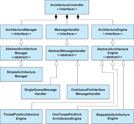
Figure 9-3. The implementation of pluggable message queuing and threading policies in the Flexible C2 Framework.
Steppable Engine. A special case of the thread pool policy, the application gets one thread that is controlled by a GUI. When the user presses a 'step' button, the thread is dispatched to process a single message. In this way, applications can be more easily debugged.
All of these policies are allowable within the C2 style, but dramatically affect how applications are developed and how much component developers have to consider when writing code. For example, it would be relatively difficult to change a Lightweight C2 Framework application from a one-thread-per-brick to a steppable threading policy, since this would require changes to each component's and connector's code. In the Flexible C2 Framework, this change can be made in one line of code in the application's main class. Still, centralized, uniform policies can make it more difficult to implement applications in which different individual components and connectors behave differently with respect to queuing and threading.
Both C2 frameworks address similar subsets of the C2-style constraints—for example, neither explicitly addresses the requirement that components and connectors are not allowed to communicate through shared memory. As explained above, this requirement is simply too expensive to implement in Java.
Because both C2 frameworks address the same architectural style and the same platform, they can be compared directly along numerous dimensions. The first is the technical dimension—examining how each framework supports (or does not support) each of the constraints of the C2 architectural style, as shown in Table 9-1. Another way of comparing the frameworks is to use the rubric we established earlier, as shown in Table 9-2.
Table 9-1. Technical Support of C2 Architectural Style.
C2 Style Constraint | Lightweight Framework Support | Flexible Framework Support |
|---|---|---|
Application functionality must be partitioned into components and connectors. | Abstract base classes are extended by application developers to create components or connectors; all application functionality must be implemented within or called by these extended base classes. | Interfaces define the requirements for components and connectors; boilerplate code is provided in abstract base classes that implement these interfaces. All application functionality must be implemented within or called by these extended base classes. |
All components and connectors communicate through two interfaces: top and bottom. | Abstract base class provides methods | Base class provides a |
Components and connectors should operate as if they run in their own threads of control. | Threads are created by component and connector base classes. | Threads are controlled by a central threading policy object called an |
Messages sent to the top interface of a component or connector should be received on the attached component or connector bottom(s) and vice versa. | Methods | Message queuing policy is centralized in an object called a |
Components and connectors should operate as though they do not share memory; all messages exchanged must be serializable. | Message objects are structured as sets of name-value pair properties, where both names and values are strings. | All messages must implement the java.io.Serializable interface, but are not constrained to any particular format. An implementation of name-value pair set messages is also provided. |
Components may be connected to at most one connector on each side; connectors may be connected to zero or more components or connectors on each side. | Connecting a component to more than one connector on any side will result in the previous connection being undone before the new one is created. | No explicit support; developers are assumed to check this constraint. |
Components may make assumptions about services provided above, but no assumptions about services provided below. | No explicit support; developers are assumed to build components in a way that obeys this constraint. | No explicit support; developers are assumed to build components in a way that obeys this constraint. |
Table 9-2. Comparison Rubric for Frameworks.
Concern | Lightweight Framework | Flexible Framework |
|---|---|---|
Platform support | Java Virtual Machine on multiple platforms. | Java Virtual Machine on multiple platforms. |
Fidelity | Assists developers in dealing with many C2-style constraints, but does not actively enforce them. | Assists developers in dealing with many C2-style constraints, but does not actively enforce them. |
Matching assumptions | Component and connector main classes must inherit from provided abstract base classes; all communication must be through messages that consist of string names and name-value pair properties. | Component and connector main classes must implement from provided Java interfaces; all communication must be through messages which can be in any serializable fomat. |
Efficiency | Framework is small and lightweight; can use only a single thread of control if desired, but this risks application deadlock. | Framework is larger but more flexible; can select from many queuing and threading policies to tune efficiency on an application-by-application basis. |
We have introduced many architectural alternatives for the Lunar Lander application; Chapter 4 presents a catalog of architectural styles, with Lunar Lander designed to fit the constraints of each style. Here, we will examine how architecture frameworks can be used to assist in the construction of working Lunar Lander implementations in two of those styles: pipe-and-filter and C2.
Note that the following sections will include code samples showing actual implementations of Lunar Lander. Certain good coding practices, such as the use of externalized string constants, comprehensive exception and null-value checking, and so on will be left out for simplicity's sake. Real implementations should take these practices into account as they apply equally when doing architecture-based software development.
Recall the introduction of a pipe-and-filter-style Lunar Lander architecture from Chapter 4, as shown in Figure 9-4. Here, Lunar Lander is broken up into three components: the first gets the burn rate from the user, the second computes new values, and the third outputs those values back to the user. Communication among the components is one-way and is done through character streams as mandated by the style.
Assuming we want to implement this application in Java, we have two obvious choices for architecture frameworks: the java.io package and the java.nio package. Because the amount of data being transferred is small and we want a simple implementation, we will implement the system using java.io. The next choice we must make is whether to implement the system as an in-process or multiprocess system.
In-Process. In an in-process system, each component will be implemented by one or more Java classes. These will communicate by way of internal streams, leveraging internal stream classes provided by the java.io framework. The application configuration will need to be created in an application main method that we write.
Multiprocess. In a multiprocess system, each component will be implemented by one or more Java classes comprising a small application. They will communicate by way of the operating-system–provided streams System.in and System.out, and the operating system will also provide the pipe connectors. The application configuration will be done on the command line.
For simplicity, we will implement the application as a multiprocess system, which saves us from having to write additional code creating our own pipes and doing tasks such as data buffering and threading. The operating system's internal services will provide buffers among the filters as well as process-level concurrency.

The first task in implementing the Lunar Lander application is to implement the three filters depicted in the proposed architecture. Because the filters are independently composable, this can be done in any order, although the order of implementation does have practical consequences. For example, in a large application, you may want to implement stubs and skeletons for testing purposes, and whether you implement the application from left-to-right or right-to-left has implications on the sorts of stubs and skeletons you must implement. For our implementation, we will work from left-to-right, starting with the GetBurnRate filter.
Recall that, in a pipe-and-filter application, all data travels from left-to-right in character streams. If applications need to communicate structured data, that structure must be encoded in the character streams. Additionally, in a strict pipe-and-filter application, all user input comes from the system input stream on the left-most filter, and all output to the user console comes from the system output stream on the right-most filter.
In this application, we need to send structured data down the pipeline. We will use a simple encoding scheme: Messages will be separated by newline characters, and each message will be preceded by a control character indicating the type of message. We will preface user-output messages with a pound sign (#) and data messages with a percent sign (%). There is nothing particularly special about these characters; they are chosen arbitrarily for this example.
Figure 9-5 shows the GetBurnRate filter implementation for Lunar Lander. This component effectively represents the user interface of the application. First, it opens a BufferedReader on the system-provided class System.in, which the Java virtual machine connects to the operating system's input stream. BufferedReader is a class provided by the java.io package for reading structured data such as lines and integers from a character stream. Next, it enters a loop, continually prompting the user for a new burn rate, reading the value, and sending it on to the next filter.
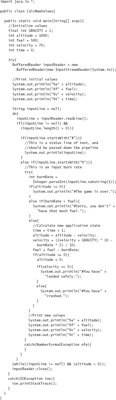
Figure 9-6 shows the implementation of the CalcNewValues filter for Lunar Lander. This is the most complex of the three filters; it must read the new burn rate from the GetBurnRate filter, store and update the application's state, and then send output values to the final filter, which formats those values for display. The basic structure of the filter is similar to that of GetBurnRate—the program opens a reader on the system input stream, processes the input, and writes data to the system output stream. Here, the filter reads two kinds of data from GetBurnRate: user messages and burn rates. User messages are passed unchanged to the next filter; burn rates trigger a computation. When a new burn rate is read, the filter updates its internal state values—the current altitude, velocity, fuel, and time—and sends those new values to the next filter. It continues until the altitude reaches zero (or less), at which point it determines whether the lander crashed or landed successfully—either way, the game is over.
The same control character scheme is used in this filter: User messages are prefaced with pound signs and data messages are prefaced with percent signs. The data messages are further coded with a second character indicating the type of data: altitude, fuel, velocity, or time. As should be obvious by this point, ensuring that the various filters have matching assumptions about the encoding scheme is critical in constructing a working application. The encoding scheme is, in effect, the interface contract for the pipe-and-filter application.
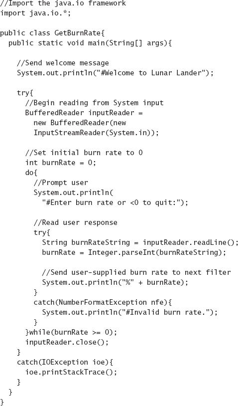
Figure 9-7 shows the implementation of the DisplayValues filter for Lunar Lander. The structural similarities to the other two filters are again evident here—the filter reads lines from system input and writes them to system output. The purpose of this filter is simply to format data for output to the console. Unformatted user messages from previous filters are output directly, while data values are annotated with descriptions for output. Here, control characters are parsed on input, but no control characters are written to the output stream; the application assumes that it is the final filter in the application and that the output data is intended for display on a console rather than as input to another application filter.
Together, these three filters make up the Lunar Lander application. One task remains, which is to determine how to instantiate and connect the application. This is done easily on the command line:
java GetBurnRate | java CalcNewValues | java DisplayValues
This command line invokes all three filters as separate processes. (The need for the invocation of java in each process is an artifact of how the Java Virtual Machine works: Each process is an instance of the virtual machine running the class passed as the first parameter to the java command.) Input from the console is fed to the system input stream of the left-most filter (GetBurnRate). The output of GetBurnRate is piped to the input of CalcNewValues. The output of CalcNewValues is likewise piped to the input of DisplayValues, and output to the console comes from the system output stream of that filter.
The architecture framework (java.io) in this implementation of Lunar Lander provides several useful services to the application. It includes a number of classes for reading and writing to the system input and output streams (such as BufferedReader). These classes allow data to be read from and written to character streams such as the system input and output streams in different ways: as individual characters, lines, integers, and so on. This allows the implementation to focus more on application functionality and less on the constraints of the architectural style.

The operating system itself provides the pipe connectors, as well as the concurrency policy for the architecture. The filter implementations in this system are closely aligned with the properties of the underlying framework and operating system, although this is not necessarily obvious from reading the code. For example, the filters assume that they are going to be running concurrently. In a few operating systems, such as MS-DOS, pipe-and-filter applications actually run in batch mode, collecting all the output from each filter before sending it to the next filter. If this version of Lunar Lander were to operate in batch mode, user messages sent out by the first two filters would not be output by the third filter until all the input to the first filter was completed. The application would not work properly in this circumstance. Additionally, the filters assume that lines written to the system output stream will be flushed automatically to the next filter. If this were not true, output messages would appear late and the application would operate in a broken or confusing way. These potential mismatching assumptions are subtle, but developers must be aware of them to determine whether an application will or will not operate as desired.
The implementation activity is often the time where underspecified or deficient architectures become evident. For example, the (admittedly simple) architecture for pipe-and-filter Lunar Lander specifies what data should pass from filter to filter, but not the format of that data. A component that communicated using XML-based data encoding, while being conformant with the architecture, would not interoperate with the filter components implemented above. Clearly, this architecture has not been elaborated to a point where component interoperability can be inferred from the architecture alone. A mismatch between XML and line-oriented data formats would be easily caught during system integration, but more subtle bugs can be even more dangerous. For example, in the case of the Mars Climate Orbiter, an interface mismatch between metric and imperial units of measure was a substantial cause for the loss of the orbiter.
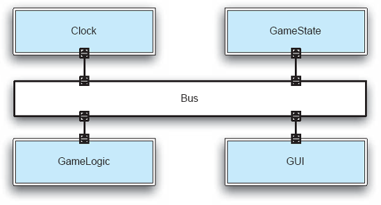
A C2-style Lunar Lander architecture shown in Figure 9-8 is different from the pipe-and-filter Lunar Lander version. First, the application functionality is broken up differently. Here, a game state component retains all game state and broadcasts updates to other components. A game logic component reads the game state, calculates a new state, and updates the game state component with that state. The GUI component is responsible for reading new burn rate values from the user and keeping the user informed as to the current game state. The most significant departure from the pipe-and-filter version is the addition of a clock component, which emits "tick" events, or messages, at periodic intervals. This changes the character of the game substantially; instead of waiting indefinitely for a new burn rate value from the user as in the pipe-and-filter version, this version of Lunar Lander is played in real-time. In this version, the game state changes whenever the clock ticks, and not when new burn rate values are entered. Here, the user may update the current burn rate as often as desired between ticks. When the clock ticks, the current burn rate value is used to calculate the new game state.
Many C2 frameworks exist for different programming languages and platforms. Assuming we want to implement the system in Java, we still must choose between frameworks such as the Lightweight C2 Framework and the Flexible C2 Framework. Because it results in slightly simpler component code, we will use the Lightweight C2 Framework for this implementation.
As with the pipe-and-filter example, we can implement these components in any order, but the order we choose has practical consequences. Because of the substrate independence (that is, layering) rules in C2, lower components may make assumptions about the services provided by upper components, but upper components may not make assumptions about lower components. (Note that this is reversed from traditional layered or virtual-machine depictions where upper layers depend on lower layers.) This means that the topmost components have no dependencies, and that lower components are progressively more dependent. We will take a least-dependent-first implementation strategy,[11] which means that the topmost components get implemented first.
The code for the GameState component is shown in Figure 9-9. The first line of code imports the c2.framework package, which belongs to the Lightweight C2 Framework. The class declaration shows that the GameState class extends the ComponentThread base class. This base class is extended by all component classes that run in their own thread of control (as is the norm in C2-style systems). This base class provides the code required for the component to receive and send requests and notifications, as well as the threading and synchronization code required to coordinate with the other components and connectors.

The first method, GameState(), is a simple boilerplate constructor. This C2 framework requires that each component and connector be given a name (in this case, gameState), as well as the class that will implement the ports (that is, message queues) used to exchange messages with attached connectors. For simplicity, all components and connectors in this architecture will use FIFO (first-in, first-out) ports—that is, ordinary queues.
The next block of code declares a set of member variables that represent the game state, including velocity, altitude, fuel remaining, current burn rate, whether the lander has landed safely, and so on. These will be read and updated as the game is played.
Each component and connector in the Lightweight C2 Framework has two primary responsibilities: handling requests (messages traveling upward in the architecture and arriving on the bottom port) and handling notifications (messages traveling downward in the architecture and arriving on the top port).
The next method, handleRequest(), is called automatically by the framework when a request arrives for this component. Recall that in the Lightweight C2 Framework, all requests and notifications have the same structure: a character string name, plus a set of name-value pair properties. This method handles two requests: an updateGameState request and a getGameState request. Upon receiving an updateGameState request, the component reads from the property set various new state values corresponding to elements of the game state. After updating the game state with the new values, the component always creates and emits a new gameState notification containing all the updated state values. Upon receiving a getGameState request, the component simply creates a new game state notification with current state values and sends it out. Sending out a request or a notification in the Lightweight C2 framework is simple. First, a new Request or Notification object is created, given a name, and populated with properties. This object can be passed to a send() method present in the abstract base class, in this case, ComponentThread. The framework routes the message appropriately.
The handleNotification() method for this component is empty; this component does not handle notifications. Because we are aware, from an architectural perspective, that no components will be connected above this one, we know that it will not receive any.
This component is entirely reactive. It is idle until a request arrives on its bottom port. If the request is of a recognized type (updateGameState or getGameState), then the component reacts, either updating its internal state and sending out a new state notification, or simply sending out the current game state. This is a relatively typical pattern of interaction for state components in C2-style systems. It is also worth noting that this component acts entirely as a data store—data validation and processing is done in other components (primarily the GameLogic component). Maintaining this separation allows architects to more easily swap out different data structures or game logic components.
The code for the Clock component is shown in Figure 9-10. The basic scaffolding for this component is similar to that for the GameState component—this component also extends ComponentThread and includes the same boilerplate constructor. Unlike the GameState component, however, the Clock handles neither requests nor notifications. Its job is simply to emit tick notifications at a predefined interval. This is done through the creation of a new clock thread in the component's start() method. The start() method is another distinguished method in the Lightweight C2 Framework; it is called by the framework automatically when the application starts. In this implementation, the clock thread creates and emits a new tick notification every five seconds (5000 milliseconds). The use of a separate clock thread is needed because the component's internal thread (provided by the ComponentThread base class) is used only for handling notifications and requests—attempting to co-opt it for sending out ticks would interfere with the message-handling behavior of the component.

The code for the GameLogic component is shown in Figure 9-11. This component is the most complex of the C2 Lunar Lander components. Structurally, it is very similar to the GameState component. Instead of responding to requests from lower components, however, it reacts to notifications coming from upper components. GameLogic responds to two kinds of notifications. The first is a gameState notification from the GameState component. Whenever the GameLogic component is notified that the game's state has changed, it updates internal state values that are used for later calculation. For a simple game like Lunar Lander, where nearly all the game state is used by the single GameLogic component, keeping separate copies of the game state in the GameState and GameLogic components may seem redundant. In more complex applications, however, logic components rarely need all the game state; instead, they would retain only the parts of the state necessary to do their own computations. An additional question that might occur to developers familiar with procedural or object-oriented programming is why the GameLogic component does not simply query the GameState component for data when it is needed. The answer lies in the architectural style—in C2, such synchronous component-to-component queries are not allowed.
The second notification handled by the GameLogic component is a clock tick from the Clock component. Recall that this version of Lunar Lander is driven not by user input of new burn rates, but by the tick of the real-time clock. When a clock tick occurs, the latest game state stored in the GameLogic component is used to calculate the next state—burning some amount of fuel, descending (or ascending) a certain distance, and so on. This state is then sent to the GameState component in an updateGameState request, which we saw handled by that component, above.
One additional detail in the GameLogic implementation is the start() method. On startup, the GameLogic component sends an asynchronous request upward to the GameState component for the initial game state. Without doing so, the calculation that occurs on the first clock tick might be based on incorrect (that is, all-zero) values as initialized in the GameLogic component.
Effectively, the behavior of the GameLogic component can be summed up by the statechart in Figure 9-12. The component starts and sends a getGameState request upward. It then idles, waiting for notifications. When a GameState notification is received, the internal state of the component is updated. When a clockTick notification is received, a new game state is calculated and a request to update the game state is sent upward.
The code for the GUI component of the Lunar Lander is shown in Figure 9-13. This component handles all interaction with the user. This particular implementation uses simple console (that is, text)-based input and output routines. The GUI component has two primary responsibilities. First, it creates an independent thread for reading user input—in this case, burn rates—from the console. Whenever a new burn rate is read, it is wrapped in an updateGameState request and sent upward. Again, a separate thread is needed here to avoid interference with the message processing thread that belongs to the component. Second, the GUI component listens for gameState notifications. Upon receiving an updated game state, the component formats and writes the state to the console.

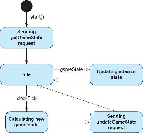

Now that all the components have been coded, they must be instantiated and connected. This is done by way of a main bootstrapping program shown in Figure 9-14. In the pipe-and-filter example, we were able to use the command-line shell to instantiate and connect the components. For a C2 application, we must instead write this bootstrapping program ourselves, calling upon the services of the Lightweight C2 Framework to instantiate and connect the components. The bootstrapper itself is relatively straightforward. First, an Architecture is created, the C2 framework's object that represents an architectural structure. Then, instances of each of the components are created, along with a single connector called bus. The components and connectors are added to the Architecture, and then links among them (called Welds in C2 parlance) are created. With everything connected, the Architecture's start() method is called, which creates internal threads, calls each component and connector's individual start() method, and performs other tasks needed to start the application.
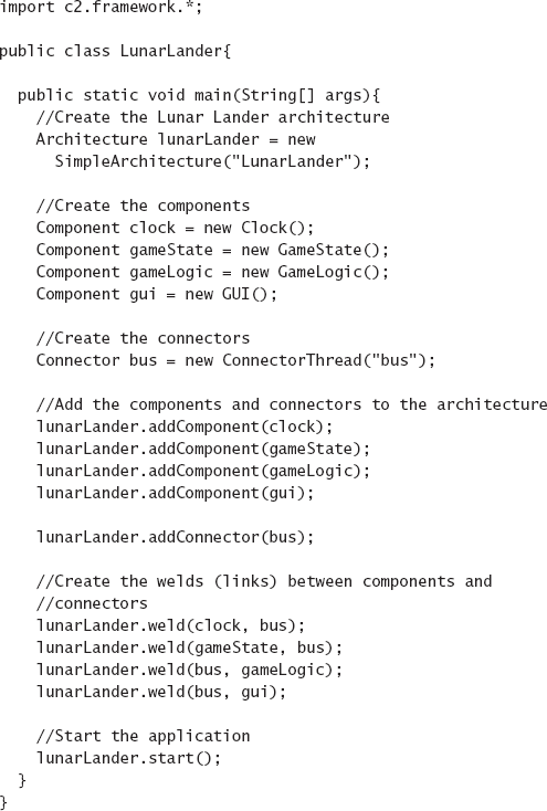
It is imperative that, to the extent possible, the design decisions in the architecture are reflected in the implemented system. Conflicts or mismatches are the hallmarks of architectural drift and erosion. Sometimes these divergences are obvious and known to the system's stakeholders, and additional documentation of these cases can help to mitigate the risks or provide plans for future work to bring the architecture and implementation back in sync. Sometimes, however, they are not, and stakeholders remain unaware of the problem. This is usually compounded in system maintenance phases, when it is expedient to update the implementation without going back and updating architectural models to match. In some ways, it is more harmful to have conflicting information in the architecture and the implementation than to have an underspecified architecture, since at least an underspecified architecture will not mislead stakeholders.
Maintaining a consistent architecture-to-implementation mapping is almost never easy, and various techniques can be used to do so. The strongest mappings are possible when architectural models become part of the system implementation and are closely connected to implementation artifacts by way of explicit mappings embedded in the models to elements implemented in architecture implementation frameworks. This strategy works well for concrete design decisions, such as structural design decisions, but is more difficult for more abstract design decisions concerning, for example, non-functional properties. In this case, stakeholders must negotiate and make decisions about how they will convince themselves that their architecture is reflected adequately in their implementation. Doubtlessly, this will involve a combined spectrum of strategies from peer review to traceability links between documents to the use of architecture implementation frameworks.
In the past set of chapters, we focused on design activities—architectural design, modeling, visualization, and analysis. In this chapter, we discussed how to move from design to implementation. Once the system is implemented, it must be deployed to its users. This is the focus of the next chapter. As we will see, maintaining architectural models with strong mappings to implementations are useful in post-implementation activities as well.
What are some architectural concerns that can be mapped to implemented systems? What strategies can be used to map these concerns?
What is the difference between one-way and round-trip mapping?
What is an architecture-implementation framework? How does an architecture-implementation framework differ from middleware?
What is the relationship between an architecture-implementation framework and an architectural style?
When might multiple frameworks be developed for a single architectural style?
What are some criteria that can be used to evaluate architecture implementation frameworks?
How do middleware and component frameworks induce architectural styles?
What are some strategies for resolving mismatches between architectural styles and middleware?
When should a new architecture-implementation framework be developed? What criteria or strategies should be used in developing the new framework?
What kinds of generative approaches can assist in moving from architecture to implementation?
Enumerate some existing architecture implementation frameworks.
How is the Standard I/O package an architecture framework for pipe-and-filter systems? How does it support the various rules and constraints of the pipe-and-filter style?
Run the implemented Lunar Lander applications in this chapter through a debugger and examine how control and data are exchanged through the framework.
The chapter compares and contrasts the Lightweight C2 Framework and the Flexible C2 Framework in terms of both structure and how they support the rules of the C2 style. Perform the same comparison for the java.io and java.nio packages vis-à-vis the pipe-and-filter style.
Choose an architecture implementation framework and a simple application, and implement that application atop the framework. Reflect on how you maintained the constraints of the architectural style in your implementation, and how the framework assisted (or hindered) you in doing so.
Choose one of the simple architectural styles in Chapter 4 and construct an architecture-implementation framework for your preferred platform/operating system combination. Enumerate the rules of the style and how your framework does or does not support those rules.
Construct an architecture framework as suggested in Exercise 4, and then use your framework for Exercise 3.
Learn about one or more middleware technologies, such as CORBA, COM, RMI, JavaBeans, and so on. Identify the architectural style rules imposed by the middleware platform. Find an example application built atop the middleware and see whether or not it obeys the style rules.
This chapter looks toward architecture-implementation frameworks as a primary method of mapping architectural design decisions to implementation artifacts. Surprisingly little has been written on the subject of such frameworks characterized in this way; Sam Malek et al. (Malek, Mikic-Rakic, and Medvidovi´ 2005) is a notable exception. However, many software systems exist that closely resemble architecture implementation frameworks without the explicit focus on styles. Some of these, such as the Standard I/O framework in C (Kernighan and Ritchie 1988) and the Java I/O (Harold 2006) and New I/O (Hitchens 2002) packages are architecture implementation frameworks in disguise, providing the services of a framework without explicitly being identified as such.
Middleware such as CORBA (Object Management Group 2001), COM and its variants (Sessions 1997), JavaBeans (JavaSoft 1996), Java RMI (Grosso 2001), Java Message Service implementations (JavaSoft 2001), and other message-passing systems such as MQSeries (IBM 2003) and MSMQ (Houston 1998) are often used as architecture-implementation frameworks. However, Elisabetta Di Nitto and David Rosenblum (Di Nitto and Rosenblum 1999) insightfully called out the fact that middleware induces an architectural style on applications that use it.
A recent trend growing in popularity is the extensive use of generative techniques, particularly under the banner of Model-Driven Architecture (Mukerji and Miller 2003), which can generate whole or partial implementations through models. Generative approaches have been identified as silver bullets before, and time will tell whether Model-Driven Architecture lives up to its initial promise.
[10] When implementations of C are available on an operating system that supports process concurrency such as UNIX or Windows, the operating system's process scheduler will generally be used to assign CPU time to each filter. However, pipe-and-filter has also been supported on single-process operating systems like DOS: In this case, the filters run entirely in sequence and the output of each filter is stored in a temporary file on the hard disk. This effectively turns all pipe-and-filter applications into batch-sequential applications.
[11] This is ordinarily called a bottom-up implementation strategy, but this terminology can be confusing in C2 architectures, where the least-dependent components are represented at the top in the canonical graphical visualization.